Nivel: Medio. Diseñe un circuito lógico que alerte al usuario cuando un sensor de agua deje de detectar líquido utilizando una compuerta NOT.
Objetivo y caso de uso
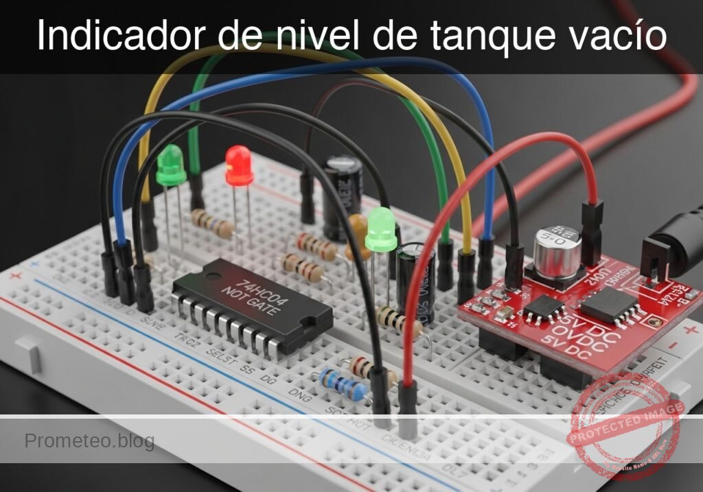
En este caso, construirá un circuito de monitoreo utilizando un inversor 74HC04 que ilumina un LED rojo cuando el nivel de líquido de un tanque cae por debajo de un punto crítico.
- Evita daños en la bomba: Detiene las bombas de agua para que no funcionen en seco en sistemas hidropónicos.
- Seguridad doméstica: Alerta cuando los tanques de reserva en la azotea están vacíos.
- Mantenimiento industrial: Indicador visual de los requisitos de recarga de refrigerante.
Resultado esperado:
* Agua presente: El sensor está abierto (entrada Lógica 1) $\rightarrow$ el LED permanece APAGADO.
* Tanque vacío: El sensor se cierra (entrada Lógica 0) $\rightarrow$ el LED se ENCIENDE.
* Nivel lógico: $V_{in} \approx 0\text{ V}$ activa la alerta; $V_{in} \approx 5\text{ V}$ indica estado normal.
Público objetivo: Estudiantes de electrónica y aficionados familiarizados con la lógica digital básica.
Materiales
- V1: Fuente de alimentación de 5 V CC, función: alimentación principal del circuito
- U1: CI Inversor Hexagonal 74HC04, función: inversión lógica
- S1: Interruptor de flotador (configurado para Cerrar cuando está Vacío), función: sensor de nivel de líquido
- R1: Resistencia de 10 kΩ, función: pull-up para señal del sensor
- R2: Resistencia de 330 Ω, función: limitación de corriente del LED
- D1: LED rojo, función: alerta visual de vacío
- C1: Condensador cerámico de 100 nF, función: desacoplo de la fuente de alimentación
Pin-out del CI utilizado
Chip seleccionado: 74HC04 (Inversor Hexagonal)
| Pin | Nombre | Función lógica | Conexión en este caso |
|---|---|---|---|
| 1 | 1A | Entrada | Conectado al nodo del sensor (SENSE_IN) |
| 2 | 1Y | Salida | Conectado al circuito LED (ALERT_OUT) |
| 7 | GND | Tierra | Conectado a 0 (GND) |
| 14 | VCC | Alimentación | Conectado a la fuente de 5V |
Guía de conexionado
- V1 se conecta entre el nodo
VCCy el nodo0(GND). - C1 se conecta entre el nodo
VCCy el nodo0(colocado físicamente cerca de U1). - R1 se conecta entre el nodo
VCCy el nodoSENSE_IN. - S1 se conecta entre el nodo
SENSE_INy el nodo0. - U1 pin 1 se conecta al nodo
SENSE_IN. - U1 pin 2 se conecta al nodo
ALERT_OUT. - U1 pin 14 se conecta a
VCC; el pin 7 se conecta a0. - R2 se conecta entre el nodo
ALERT_OUTy el nodoLED_ANODE. - D1 se conecta entre el nodo
LED_ANODE(Ánodo) y el nodo0(Cátodo).
Diagrama de bloques conceptual
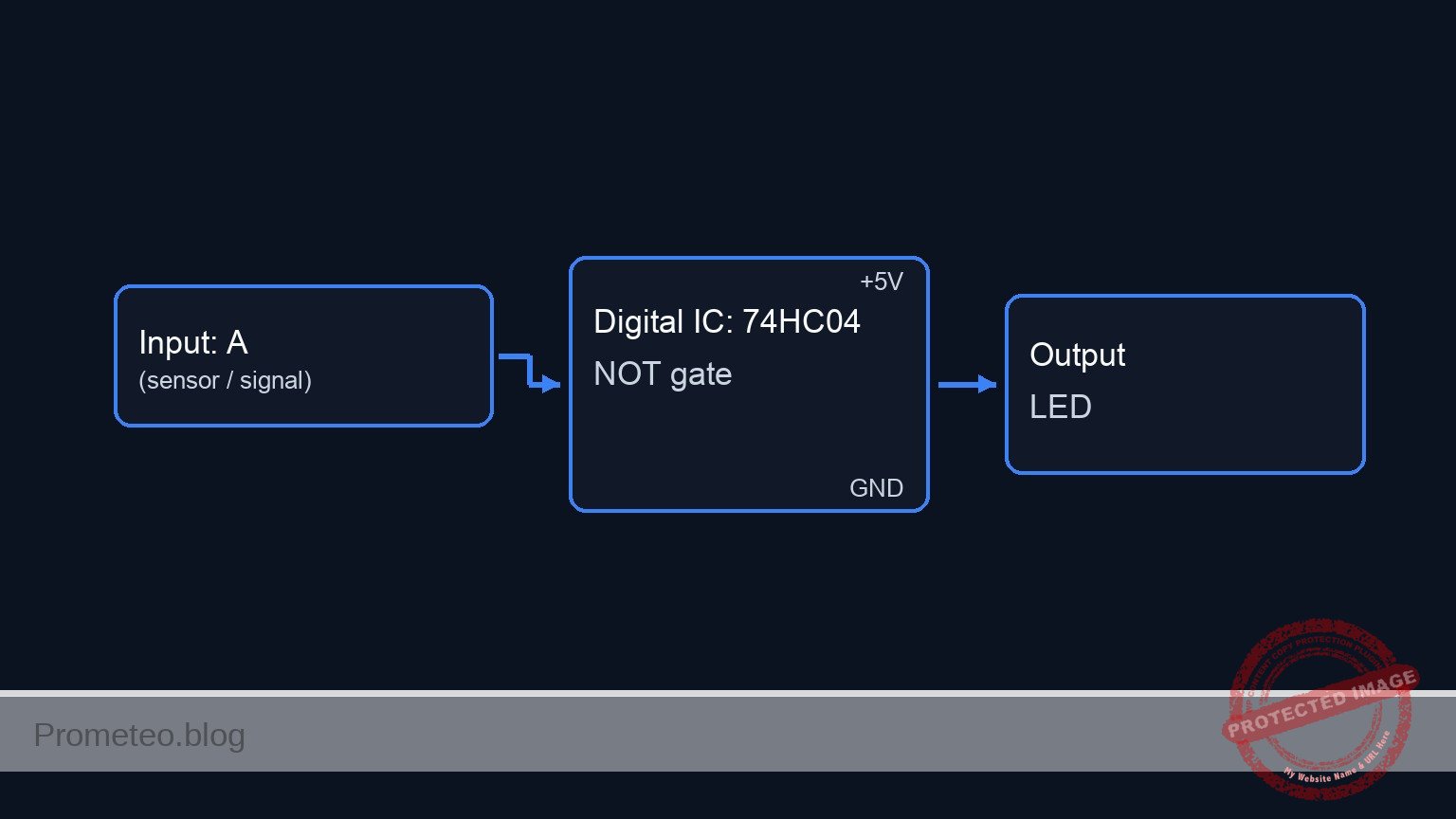
Esquemático
[ INPUT / SENSOR ]                 [ LOGIC PROCESSING ]                 [ OUTPUT / ALERT ]

[ VCC 5V ] --> [ R1: 10k ] --+
               (Pull-Up)     |
                             |
                             V
                        (SENSE_IN) ---->+------------------+
                        (Pin 1)         |    U1: 74HC04    |
                             ^          |   Hex Inverter   |--(ALERT_OUT)--> [ R2: 330R ] --> [ D1: Red LED ] --> GND
                             |          |   (Pin 1 -> 2)   |  (Pin 2)        (Limiting)       (Anode/Cathode)
[ GND 0V ] --> [ S1: Float ]-+          +------------------+
               (Switch)                           ^
                                                  |
                                            [ C1: 100nF ]
                                            (Decoupling)
                                            (VCC / GND)
Tabla de verdad
| Estado del agua | Interruptor del sensor (S1) | Voltaje de entrada (Pin 1) | Entrada lógica | Voltaje de salida (Pin 2) | Estado del LED |
|---|---|---|---|---|---|
| Lleno | ABIERTO | 5 V (vía Pull-up) | 1 | 0 V | APAGADO |
| Vacío | CERRADO | 0 V (conectado a GND) | 0 | 5 V | ENCENDIDO |
Mediciones y pruebas
- Verificación de alimentación: Mida el voltaje entre
VCCy0. Asegúrese de que sea estable a 5 V. - Simulación de tanque lleno: Levante manualmente el flotador (abra S1). Mida el voltaje en
SENSE_IN. Debería ser $\approx 5\text{ V}$. Verifique que el LED esté APAGADO. - Simulación de tanque vacío: Deje caer el flotador (cierre S1). Mida el voltaje en
SENSE_IN. Debería ser $\approx 0\text{ V}$. - Salida lógica: Mientras S1 está cerrado (Vacío), mida el voltaje en
ALERT_OUT. Debería ser $\approx 5\text{ V}$. - Consumo de corriente: Mida la corriente a través de D1 ($I_{led}$) cuando esté ENCENDIDO. Debería ser de aproximadamente 10–12 mA dependiendo de la caída de voltaje específica del LED.
Netlist SPICE y simulación
Netlist SPICE de referencia (ngspice) — extractoNetlist SPICE completo (ngspice)
* Practical case: Empty Tank Level Indicator

* ==============================================================================
* BILL OF MATERIALS & COMPONENTS
* ==============================================================================

* --- Power Supply ---
* V1: 5 V DC power supply
V1 VCC 0 DC 5

* --- Decoupling ---
* C1: 100 nF ceramic capacitor (Power supply decoupling)
C1 VCC 0 100n

* --- Sensor Input Section ---
* R1: 10 kΩ resistor (Pull-up for sensor signal)
R1 VCC SENSE_IN 10k

* S1: Float switch (SPST)
* Wiring: Connects between node SENSE_IN and node GND.
* ... (truncated in public view) ...
Copia este contenido en un archivo .cir y ejecútalo con ngspice.
* Practical case: Empty Tank Level Indicator

* ==============================================================================
* BILL OF MATERIALS & COMPONENTS
* ==============================================================================

* --- Power Supply ---
* V1: 5 V DC power supply
V1 VCC 0 DC 5

* --- Decoupling ---
* C1: 100 nF ceramic capacitor (Power supply decoupling)
C1 VCC 0 100n

* --- Sensor Input Section ---
* R1: 10 kΩ resistor (Pull-up for sensor signal)
R1 VCC SENSE_IN 10k

* S1: Float switch (SPST)
* Wiring: Connects between node SENSE_IN and node GND.
* Simulation: Modeled as a Voltage Controlled Switch (SW).
* Logic:
*   - Tank Full (Float Up) -> Switch Open -> SENSE_IN pulled to VCC.
*   - Tank Empty (Float Down) -> Switch Closed -> SENSE_IN pulled to GND.
* Control Source V_FLOAT_ACT simulates the float movement.
*   - 0V = Float Up (Full)
*   - 5V = Float Down (Empty)
S1 SENSE_IN 0 FLOAT_CTRL 0 SW_FLOAT
.model SW_FLOAT SW(Vt=2.5 Ron=0.1 Roff=10Meg)

* Stimulus: Float starts Up (Full), drops to Down (Empty) at 50us, returns at 200us.
V_FLOAT_ACT FLOAT_CTRL 0 PULSE(0 5 50u 1u 1u 150u 400u)

* --- Logic Processing ---
* U1: 74HC04 Hex Inverter
* Wiring Guide: Pin 1 (In) -> SENSE_IN, Pin 2 (Out) -> ALERT_OUT
* Power: Pin 14 -> VCC, Pin 7 -> GND
* Implemented as a subcircuit to strictly map pins.
XU1 SENSE_IN ALERT_OUT 0 VCC 74HC04_GATE

* Subcircuit definition for one gate of 74HC04
.subckt 74HC04_GATE IN OUT GND VCC
    * Behavioral voltage source for robust logic inversion
    * Uses sigmoid function for convergence: Vout = VCC if Vin < 2.5V
    B1 OUT GND V = V(VCC) * (1 / (1 + exp(50 * (V(IN) - 2.5))))
.ends

* --- Output Alert ---
* R2: 330 Ω resistor (LED current limiting)
R2 ALERT_OUT LED_ANODE 330

* D1: Red LED (Visual empty alert)
* Wiring: Anode -> LED_ANODE, Cathode -> GND
D1 LED_ANODE 0 LED_RED
.model LED_RED D(IS=1e-14 N=2 RS=5 BV=5 IBV=10u CJO=40p)

* ==============================================================================
* ANALYSIS COMMANDS
* ==============================================================================

* Operating Point Analysis
.op

* Transient Analysis
* Run for 500us to capture the float switch activation cycle
.tran 1u 500u

* Output Printing
* Monitor Sensor Input, Inverter Output, and LED Voltage
.print tran V(SENSE_IN) V(ALERT_OUT) V(LED_ANODE) V(FLOAT_CTRL)

.end
Resultados de Simulación (Transitorio)

Show raw data table (1190 rows)
Index   time            v(sense_in)     v(alert_out)    v(led_anode)
0	0.000000e+00	4.995005e+00	3.316079e-54	-1.70080e-28
1	1.000000e-08	4.995005e+00	3.316079e-54	-9.73961e-29
2	2.000000e-08	4.995005e+00	3.316079e-54	-1.41516e-29
3	4.000000e-08	4.995005e+00	3.316079e-54	8.723601e-29
4	8.000000e-08	4.995005e+00	3.316079e-54	1.163518e-28
5	1.600000e-07	4.995005e+00	3.316079e-54	4.380930e-29
6	3.200000e-07	4.995005e+00	3.316079e-54	-1.45299e-29
7	6.400000e-07	4.995005e+00	3.316079e-54	-1.01395e-29
8	1.280000e-06	4.995005e+00	3.316079e-54	-5.46095e-32
9	2.280000e-06	4.995005e+00	3.316079e-54	4.098577e-31
10	3.280000e-06	4.995005e+00	3.316079e-54	2.282032e-32
11	4.280000e-06	4.995005e+00	3.316079e-54	-9.50625e-33
12	5.280000e-06	4.995005e+00	3.316079e-54	-1.09186e-33
13	6.280000e-06	4.995005e+00	3.316079e-54	1.911218e-34
14	7.280000e-06	4.995005e+00	3.316079e-54	3.847480e-35
15	8.280000e-06	4.995005e+00	3.316079e-54	-2.97995e-36
16	9.280000e-06	4.995005e+00	3.316079e-54	-1.15977e-36
17	1.028000e-05	4.995005e+00	3.316079e-54	1.723722e-38
18	1.128000e-05	4.995005e+00	3.316079e-54	3.117034e-38
19	1.228000e-05	4.995005e+00	3.316079e-54	1.177223e-39
20	1.328000e-05	4.995005e+00	3.316079e-54	-7.52109e-40
21	1.428000e-05	4.995005e+00	3.316079e-54	-6.99870e-41
22	1.528000e-05	4.995005e+00	3.316079e-54	1.597704e-41
23	1.628000e-05	4.995005e+00	3.316079e-54	2.660714e-42
... (1166 more rows) ...
* Practical case: Empty Tank Level Indicator

* -----------------------------------------------------------------------------
* Power Supply
* V1 connects between node VCC and node 0 (GND)
* -----------------------------------------------------------------------------
V1 VCC 0 DC 5

* -----------------------------------------------------------------------------
* Decoupling Capacitor
* C1 connects between node VCC and node 0
* -----------------------------------------------------------------------------
C1 VCC 0 100n

* -----------------------------------------------------------------------------
* Sensor / Input Stage
* S1: Float switch (configured to Close when Empty)
* R1: Pull-up resistor
* Wiring: R1 between VCC and SENSE_IN. S1 between SENSE_IN and 0.
*
* Simulation Note: S1 is modeled as a Voltage-Controlled Switch driven by
* a PULSE source (V_SW_CTRL) to simulate the physical action of the tank
* emptying and the switch closing.
* -----------------------------------------------------------------------------
R1 VCC SENSE_IN 10k

* Switch S1
* Controlled by node SW_CTRL.
* Control = 0V -> Switch Open (Tank Full, SENSE_IN pulled High)
* Control = 5V -> Switch Closed (Tank Empty, SENSE_IN pulled Low)
S1 SENSE_IN 0 SW_CTRL 0 FLOAT_SW_MODEL

* Switch Model
.model FLOAT_SW_MODEL SW(Vt=2.5 Ron=0.1 Roff=100M)

* Stimulus: User/Environment simulation
* Pulse starts at 0V (Full), pulses to 5V (Empty) at 100us, holds for 200us.
V_SW_CTRL SW_CTRL 0 PULSE(0 5 100u 1u 1u 200u 500u)

* -----------------------------------------------------------------------------
* Logic Stage: U1 74HC04 Hex Inverter
* Wiring: Pin 1 (Input) -> SENSE_IN, Pin 2 (Output) -> ALERT_OUT
*         Pin 14 -> VCC, Pin 7 -> 0 (GND)
* Implemented as a subcircuit to expose pins and provide robust behavioral logic.
* -----------------------------------------------------------------------------
XU1 SENSE_IN ALERT_OUT 0 VCC 74HC04_GATE

.subckt 74HC04_GATE IN OUT GND VCC
* Robust behavioral model of a CMOS Inverter using sigmoid function
* Vout = VCC if Vin < Vth, Vout = 0 if Vin > Vth
* Vth set to VCC/2. Steepness factor k=50.
B_INV OUT GND V = V(VCC) / (1 + exp(50 * (V(IN) - V(VCC)/2)))
.ends

* -----------------------------------------------------------------------------
* Output Stage: Indicator LED
* Wiring: R2 between ALERT_OUT and LED_ANODE. D1 between LED_ANODE and 0.
* -----------------------------------------------------------------------------
R2 ALERT_OUT LED_ANODE 330

* D1 Red LED
D1 LED_ANODE 0 RED_LED_MODEL

* LED Model (Approximate Red LED Vf ~ 1.8V @ 10mA)
.model RED_LED_MODEL D(IS=1e-18 N=2 RS=5 BV=5 IBV=10u CJO=10p)

* -----------------------------------------------------------------------------
* Analysis Commands
* -----------------------------------------------------------------------------
.op
* Transient analysis: 1us step, 500us total duration
.tran 1u 500u

* Print results to log (Required)
.print tran V(SENSE_IN) V(ALERT_OUT) V(LED_ANODE) V(SW_CTRL)

.end
Resultados de Simulación (Transitorio)

Show raw data table (1080 rows)
Index   time            v(sense_in)     v(alert_out)    v(led_anode)
0	0.000000e+00	4.999950e-05	5.000000e+00	1.948002e+00
1	1.000000e-08	4.999950e-05	5.000000e+00	1.947999e+00
2	2.000000e-08	4.999950e-05	5.000000e+00	1.947999e+00
3	4.000000e-08	4.999950e-05	5.000000e+00	1.947999e+00
4	8.000000e-08	4.999950e-05	5.000000e+00	1.947999e+00
5	1.600000e-07	4.999950e-05	5.000000e+00	1.947999e+00
6	3.200000e-07	4.999950e-05	5.000000e+00	1.947999e+00
7	6.400000e-07	4.999950e-05	5.000000e+00	1.947999e+00
8	1.280000e-06	4.999950e-05	5.000000e+00	1.947999e+00
9	2.280000e-06	4.999950e-05	5.000000e+00	1.947999e+00
10	3.280000e-06	4.999950e-05	5.000000e+00	1.947999e+00
11	4.280000e-06	4.999950e-05	5.000000e+00	1.947999e+00
12	5.280000e-06	4.999950e-05	5.000000e+00	1.947999e+00
13	6.280000e-06	4.999950e-05	5.000000e+00	1.947999e+00
14	7.280000e-06	4.999950e-05	5.000000e+00	1.947999e+00
15	8.280000e-06	4.999950e-05	5.000000e+00	1.947999e+00
16	9.280000e-06	4.999950e-05	5.000000e+00	1.947999e+00
17	1.028000e-05	4.999950e-05	5.000000e+00	1.947999e+00
18	1.128000e-05	4.999950e-05	5.000000e+00	1.947999e+00
19	1.228000e-05	4.999950e-05	5.000000e+00	1.947999e+00
20	1.328000e-05	4.999950e-05	5.000000e+00	1.947999e+00
21	1.428000e-05	4.999950e-05	5.000000e+00	1.947999e+00
22	1.528000e-05	4.999950e-05	5.000000e+00	1.947999e+00
23	1.628000e-05	4.999950e-05	5.000000e+00	1.947999e+00
... (1056 more rows) ...