
Level: Basic. Learn to identify and fix an NPN transistor stuck in the active region.
Objective and use case
In this practical case, you will build a standard Low-Side Switch using a BJT (Bipolar Junction Transistor) to control a high-current load. However, the circuit will contain a deliberate flaw in the base resistor selection to demonstrate the difference between the Active Region and Saturation.
- Understanding Transistor Modes: Learn why a transistor acts as a resistor instead of a switch if not biased correctly.
- Power Dissipation: Understand why partially open transistors overheat.
- Troubleshooting: Practice measuring VCE to diagnose switching efficiency.
Expected outcome:
* Initially, the high-current LED will be surprisingly dim.
* Voltage measurement across the transistor (VCE) will be high (> 2 V).
* After the fix, the LED will be bright, and VCE will drop to near 0 V.
* Target audience: Beginners and students familiar with basic Ohm’s Law.
Materials
- V1: 5 V DC Power Supply, function: Main circuit power.
- Q1: 2N2222 NPN Transistor, function: Low-side switch.
- D1: High-Brightness White LED, function: The heavy load (requires approx. 80-100 mA).
- R1: 33 Ω resistor (1/2 Watt), function: LED current limiting (Rload).
- R2: 100 kΩ resistor, function: Incorrect Base resistor (Test Case).
- R3: 1 kΩ resistor, function: Correct Base resistor (Solution).
- S1: SPST Switch or Jumper wire, function: Input control.
Wiring guide
Construct the circuit using the following netlist connections. Pay attention to the node names.
- V1 (5 V) connects to node
VCC. - V1 (GND) connects to node
0. - S1 connects between
VCCand nodeSWITCH_OUT. - R2 (100 kΩ) connects between
SWITCH_OUTand nodeBASE. - Q1 Base connects to node
BASE. - Q1 Emitter connects to node
0(GND). - Q1 Collector connects to node
COLLECTOR. - D1 Anode connects to node
VCC. - D1 Cathode connects to node
LED_CATHODE. - R1 (33 Ω) connects between
LED_CATHODEandCOLLECTOR.
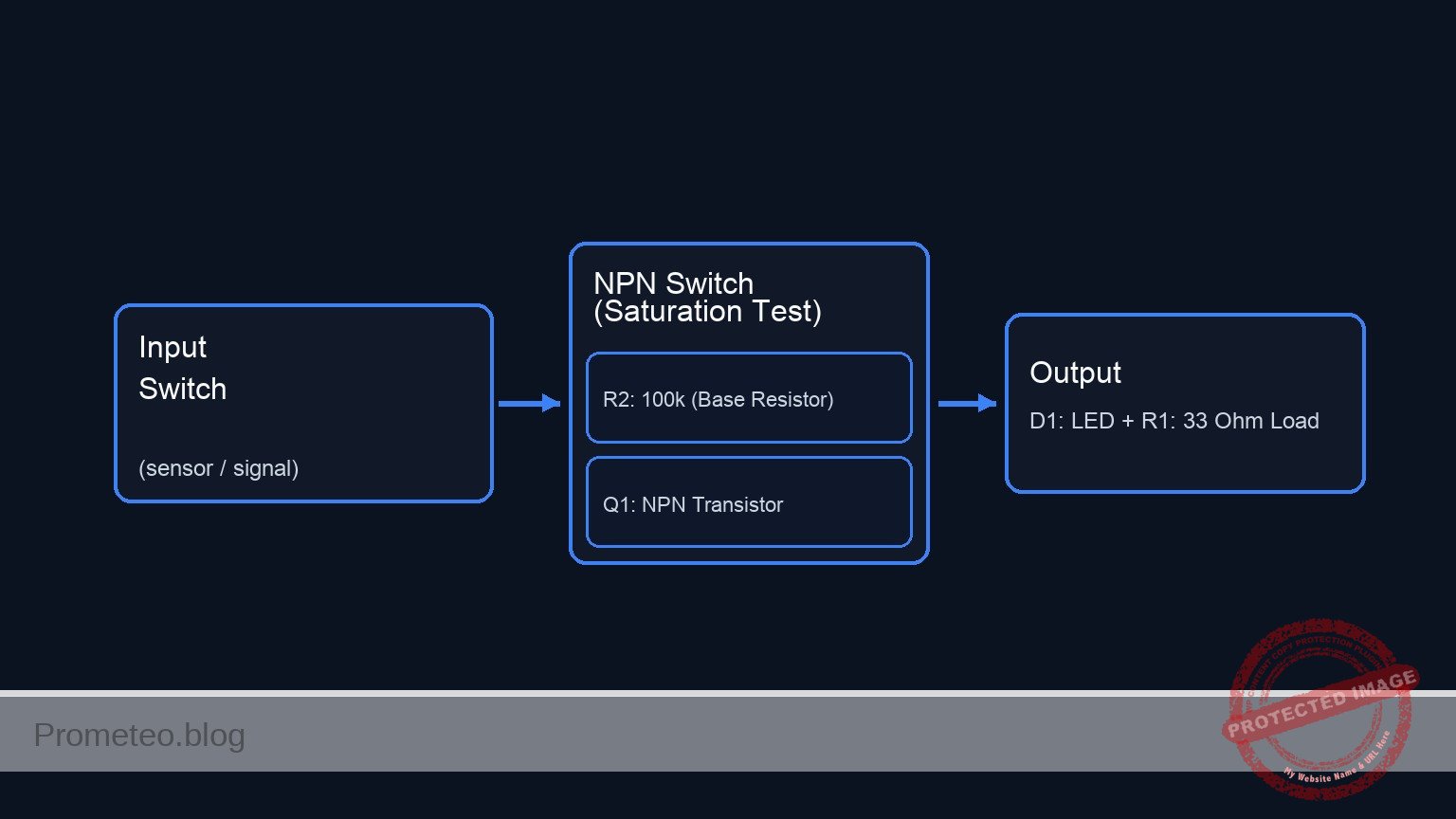
Conceptual block diagram
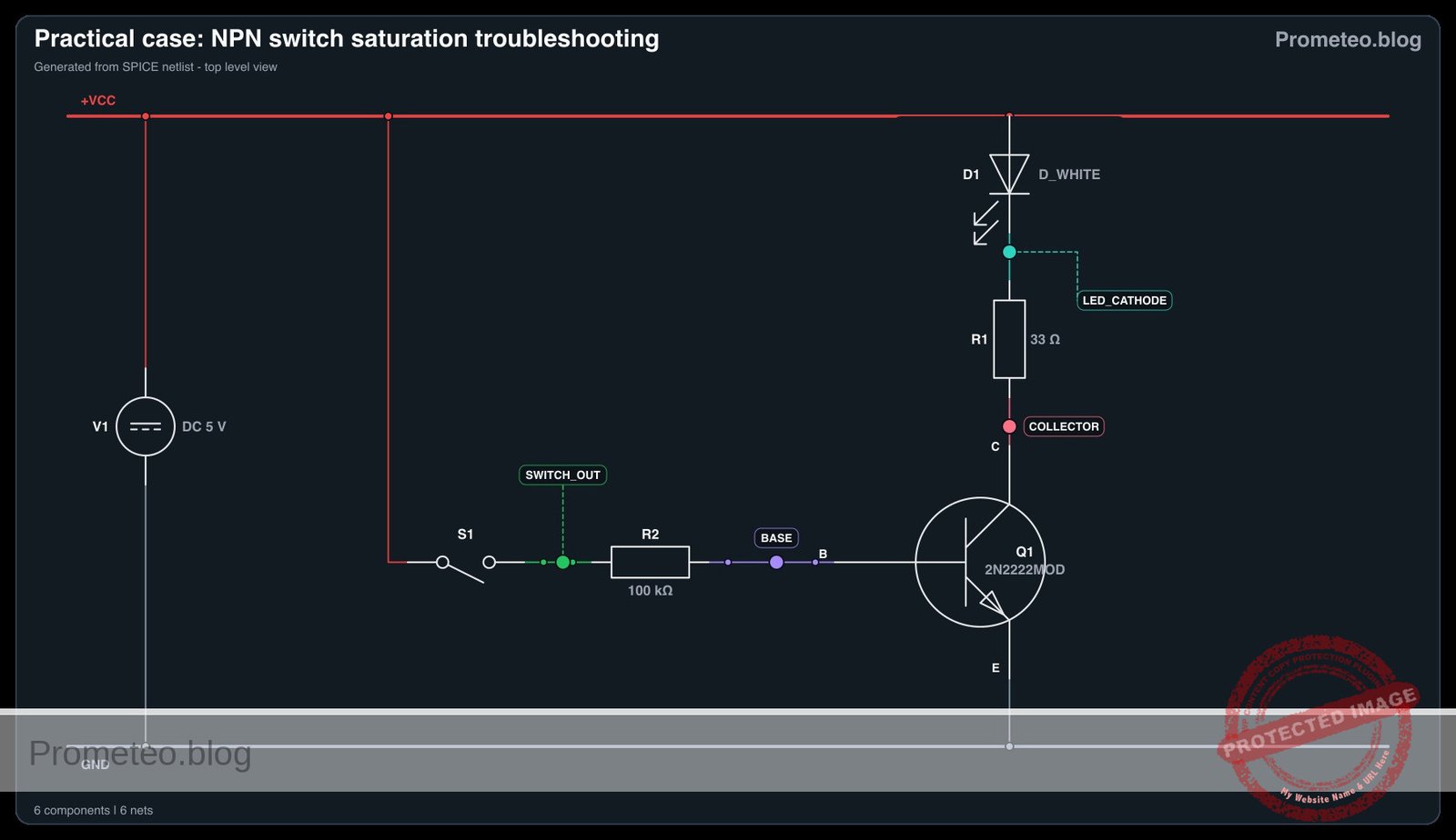
Schematic
Title: Practical case: NPN Switch Saturation Troubleshooting

(1) CONTROL PATH (Base Current Drive)
    VCC --> [ S1: Switch ] --(SWITCH_OUT)--> [ R2: 100k ] --(BASE)--> [ Q1: Base ]
                                                                           |
                                                                    (Activates Switch)
                                                                           |
                                                                           V

(2) POWER PATH (High Current Load)
    VCC --> [ D1: LED ] --(LED_CATHODE)--> [ R1: 33 Ohm ] --(COLLECTOR)--> [ Q1: Collector ]
                                                                                 |
                                                                           (Current Flow)
                                                                                 |
                                                                                 V
                                                                           [ Q1: Emitter ] --> GND
Electrical diagram
Measurements and tests
Follow this procedure to analyze the circuit behavior before applying the fix.
- Visual Inspection: Close switch S1. Observe the brightness of D1. It should be noticeably dim for a high-brightness LED.
- Base Voltage Check: Measure voltage at node
BASErelative to GND. It should be approximately 0.7 V. - Collector Voltage (VCE) Check: Measure voltage at node
COLLECTORrelative to GND (across the transistor).- Expectation for a perfect switch: ~0 V.
- Actual measurement: You will likely measure a significant voltage (e.g., 2 V to 4 V depending on the exact gain of your specific Q1).
- Calculated Current: Calculate the current entering the base: IB = (5 V – 0.7 V) / 100 kΩ.
SPICE netlist and simulation
Reference SPICE Netlist (ngspice) — excerptFull SPICE netlist (ngspice)
* Practical case: NPN Switch Saturation Troubleshooting
.width out=256

* --- Power Supply ---
V1 VCC 0 DC 5

* --- Input Control (S1) ---
* S1 connects VCC to SWITCH_OUT. Modeled as a voltage-controlled switch
* driven by a PULSE source to simulate user actuation.
S1 VCC SWITCH_OUT CTRL 0 SW_IDEAL
Vctrl CTRL 0 PULSE(0 5 0 1u 1u 50u 100u)
.model SW_IDEAL SW(Vt=2.5 Ron=0.01 Roff=100Meg)

* --- Circuit Components ---
* R2: Incorrect Base resistor (100k) causing weak saturation.
* This matches the "Troubleshooting" state defined in the Wiring Guide.
R2 SWITCH_OUT BASE 100k

* Note: R3 (1k) is listed in the BOM as the 'Solution' but is not connected
* in the current wiring guide configuration. It is omitted to prevent floating nodes.
* ... (truncated in public view) ...
Copy this content into a .cir file and run with ngspice.
* Practical case: NPN Switch Saturation Troubleshooting
.width out=256

* --- Power Supply ---
V1 VCC 0 DC 5

* --- Input Control (S1) ---
* S1 connects VCC to SWITCH_OUT. Modeled as a voltage-controlled switch
* driven by a PULSE source to simulate user actuation.
S1 VCC SWITCH_OUT CTRL 0 SW_IDEAL
Vctrl CTRL 0 PULSE(0 5 0 1u 1u 50u 100u)
.model SW_IDEAL SW(Vt=2.5 Ron=0.01 Roff=100Meg)

* --- Circuit Components ---
* R2: Incorrect Base resistor (100k) causing weak saturation.
* This matches the "Troubleshooting" state defined in the Wiring Guide.
R2 SWITCH_OUT BASE 100k

* Note: R3 (1k) is listed in the BOM as the 'Solution' but is not connected
* in the current wiring guide configuration. It is omitted to prevent floating nodes.

* Q1: NPN Transistor Switch (Low-side)
Q1 COLLECTOR BASE 0 2N2222MOD

* D1: High-Brightness White LED
D1 VCC LED_CATHODE D_WHITE

* R1: LED Current Limiting Resistor
R1 LED_CATHODE COLLECTOR 33

* --- Models ---
* Generic NPN Model for 2N2222
.model 2N2222MOD NPN(IS=1E-14 BF=200 VAF=100 IKF=0.3 RB=10 RC=0.3 RE=0.2 CJE=25p CJC=8p)

* Approximate White LED Model (High Forward Voltage)
.model D_WHITE D(IS=1p N=3.5 RS=5 BV=5 IBV=10u)

* --- Analysis Commands ---
* Transient analysis to visualize switching behavior
.tran 1u 200u

* Output identification:
* Input: V(SWITCH_OUT)
* Output: V(COLLECTOR) (Low-side switch voltage)
.print tran V(SWITCH_OUT) V(COLLECTOR) V(BASE) V(LED_CATHODE)

.end
Simulation Results (Transient Analysis)

Show raw data table (271 rows)
Index   time            v(switch_out)   v(collector)    v(base)         v(led_cathode)
0	0.000000e+00	5.375300e-01	3.548129e+00	5.330675e-01	3.548432e+00
1	1.000000e-08	5.375300e-01	3.548129e+00	5.330675e-01	3.548432e+00
2	2.000000e-08	5.375300e-01	3.548129e+00	5.330675e-01	3.548432e+00
3	4.000000e-08	5.375300e-01	3.548129e+00	5.330676e-01	3.548432e+00
4	8.000000e-08	5.375300e-01	3.548129e+00	5.330676e-01	3.548432e+00
5	1.600000e-07	5.375300e-01	3.548129e+00	5.330676e-01	3.548432e+00
6	3.200000e-07	5.375300e-01	3.548129e+00	5.330676e-01	3.548432e+00
7	3.562500e-07	5.375300e-01	3.548129e+00	5.330676e-01	3.548432e+00
8	4.196875e-07	5.375300e-01	3.548129e+00	5.330676e-01	3.548432e+00
9	4.372461e-07	5.375300e-01	3.548129e+00	5.330676e-01	3.548432e+00
10	4.679736e-07	5.375300e-01	3.548129e+00	5.330676e-01	3.548432e+00
11	5.019934e-07	5.000000e+00	3.537721e+00	5.508590e-01	3.538060e+00
12	5.700330e-07	5.000000e+00	3.337558e+00	5.996484e-01	3.340559e+00
13	6.907446e-07	5.000000e+00	3.004466e+00	6.704095e-01	3.063080e+00
14	8.252066e-07	5.000000e+00	2.710645e+00	7.051011e-01	2.922994e+00
15	1.000000e-06	5.000000e+00	2.604154e+00	7.130054e-01	2.886751e+00
16	1.026892e-06	5.000000e+00	2.605141e+00	7.129945e-01	2.887005e+00
17	1.080677e-06	5.000000e+00	2.606105e+00	7.129106e-01	2.887380e+00
18	1.188247e-06	5.000000e+00	2.607032e+00	7.128469e-01	2.887677e+00
19	1.403386e-06	5.000000e+00	2.607269e+00	7.128312e-01	2.887753e+00
20	1.833664e-06	5.000000e+00	2.607219e+00	7.128340e-01	2.887737e+00
21	2.694221e-06	5.000000e+00	2.607248e+00	7.128325e-01	2.887747e+00
22	3.694221e-06	5.000000e+00	2.607227e+00	7.128335e-01	2.887740e+00
23	4.694221e-06	5.000000e+00	2.607243e+00	7.128328e-01	2.887745e+00
... (247 more rows) ...
Common mistakes and how to avoid them
- Confusing Pinout: Placing the transistor backwards (Collector and Emitter swapped) often allows some current to flow but with very low gain, mimicking this specific problem. Always verify the datasheet.
- Assuming hFE is Constant: Students often use the maximum hFE (e.g., 300) for calculation. For switching, you must assume a much lower «forced beta» (usually 10) to ensure saturation.
- Ignoring Power Ratings: If the transistor is dropping 3 V and passing 50 mA, it is dissipating 150mW. While safe for a 2N2222, this heat is wasted energy.
Troubleshooting
- LED does not light up at all: Check if the LED polarity is correct (Anode to VCC). Verify S1 is actually connecting power to R2.
- Transistor gets hot: If VCE is high and current is flowing, the transistor is acting as a resistor. This confirms it is in the Active Region.
- VCE reads 5 V: The transistor is not turning on at all. Check if R2 is connected properly or if the Base-Emitter junction is blown.
Diagnosis and Solution
Follow this pedagogical sequence to understand and resolve the issue.
1. The Problem (Symptom)
You have assembled the circuit, closed the switch, but the High-Current LED barely glows. It looks weak. Why is this happening if the transistor is supposed to be a «switch»?
2. The Investigation
Take your multimeter. Measure the voltage between the Collector and Emitter (VCE).
* If Q1 were a closed switch, you would expect 0 V (or very close to it).
* However, you will likely find 2 V to 3 V.
* Now, calculate the Base Current you are providing: IB = (VIN – 0.7 V) / RB. With 100 kΩ, IB is tiny (~43µ A).
🕵️ See Diagnosis and Solution (Click to reveal)
**3. The Revelation**
The transistor does not have enough base current to fully open the «valve».
* To act as a switch, the transistor must be in **Saturation**.
* Currently, it is in the **Active (Linear) Region**.
* The condition IB × hFE < Icload is occurring. The transistor is limiting the current and acting like a variable resistor, dropping voltage and wasting power.**4. The Solution**
You must force the transistor into saturation.
1. **Recalculate RB:** We generally use a "Forced Beta" of 10 for switching. Target IB = Iload / 10.
2. **The Fix:** Remove the 100 kΩ resistor (R2) and replace it with the **1 kΩ resistor (R3)**.
3. **Verify:** Turn the switch on. The LED should shine brightly. Measure VCE again; it should now be **< 0.2 V** (Saturation Voltage).
Possible improvements and extensions
- Darlington Pair: Use two transistors configured as a Darlington pair to increase the total gain, allowing the 100 kΩ resistor to successfully switch the load (at the cost of a higher Vcesat drop of ~1.2 V).
- MOSFET Upgrade: Replace the 2N2222 with an N-Channel MOSFET (like a 2N7000) to achieve near-zero gate current requirements and lower voltage drop.
More Practical Cases on Prometeo.blog
Find this product and/or books on this topic on Amazon
As an Amazon Associate, I earn from qualifying purchases. If you buy through this link, you help keep this project running.
Quick Quiz

Telecommunications Electronics Engineer and Computer Engineer (official degrees in Spain).

