Objective and use case
What you’ll build: A Jetson TX2 app that reads a K‑type thermocouple via an Adafruit MAX31855 and an analog channel via an Adafruit MCP3008 over SPI, timestamps both streams, logs CSV, and reports MAX31855 fault/health bits in real time. It also raises alarms and toggles a GPIO/relay on thresholds or sensor faults.
Why it matters / Use cases
- Oven/reflow profiling: Capture preheat/soak/reflow/cool‑down at 10 Hz; verify 1–3 °C/s ramps, peak 240–250 °C within ±3 °C, and soak 150–180 °C for 60–120 s.
- Lab thermal cycling: Monitor DUT temperature and trigger alarms if >85 °C with <100 ms reaction; correlate a fan PWM or supply rail (via MCP3008 at 1 kHz) to temperature steps and lag.
- 3D printer/maker projects: Validate extruder/hotbed temperatures (±2 °C typical with MAX31855); read a potentiometer or airflow sensor to tune PID and keep overshoot <5 °C.
- Field data logging: Run as an edge logger saving CSV and streaming 1 s summaries; hardware SPI provides low‑jitter sampling (<1 ms at 1 kHz ADC) even under CPU load.
- Safety cutoffs: Use the ADC to read a knob/setpoint or thermistor voltage and trip a GPIO/relay if temperature exceeds limits or if TC faults occur (OC/SCG/SCV), with fail‑safe latency <50 ms.
Expected outcome
- Thermocouple updates at 4–10 Hz (MAX31855 update 100–250 ms) with ±2 °C accuracy; ADC sampling 200–1000 Hz with <5 mV RMS noise using MCP3008 at 5 MHz SPI.
- End‑to‑end latency: ADC sample‑to‑log <5 ms, thermocouple sample‑to‑log 50–150 ms; alarm reaction <50 ms; ADC jitter <1 ms.
- Resource use on TX2: 3–8% CPU on one core, 0% GPU, <100 MB RAM; sustained logging without drops for >24 h.
- Structured CSV with timestamp, TC °C, cold‑junction °C, ADC volts, and MAX31855 fault bits (OC/SCG/SCV); 24 h at 10 Hz ≈ 0.86 M rows (~30–60 MB).
- Robust behavior: detects open/short conditions, debounces faults, and resumes cleanly after sensor disconnect/reconnect.
Audience: Embedded/Linux makers, test/validation engineers; Level: Intermediate (SPI, GPIO, Linux user‑space).
Architecture/flow: TX2 SPI0 drives MAX31855 (CS0) and MCP3008 (CS1) at ~5 MHz; a reader polls the MAX31855 at 10 Hz (respecting its update rate) while a second thread batches 8–16 MCP3008 samples every 10 ms (~800–1600 SPS), timestamps with CLOCK_MONOTONIC, writes CSV in 100 ms flushes, and emits optional MQTT/UDP summaries; threshold and fault logic assert a GPIO/relay with <50 ms latency; typical load 3–8% CPU, 0% GPU.
Prerequisites
1) JetPack and model verification (run on the Jetson TX2):
cat /etc/nv_tegra_release
jetson_release -v || true
uname -a
dpkg -l | grep -E 'nvidia|tensorrt'
2) Confirm L4T 32.x (JetPack 4.x) for TX2 is installed and SPI device nodes exist or can be enabled.
3) Basic terminal proficiency, sudo access, and internet for package/model downloads.
4) Optional: CSI camera connected to test GStreamer pipeline.
Materials (with exact model)
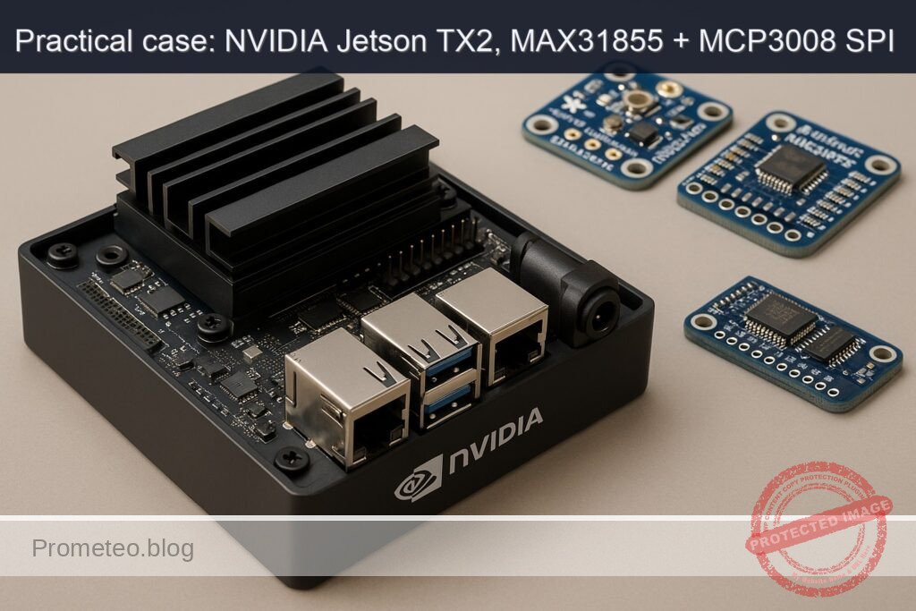
- NVIDIA Jetson TX2 Developer Kit + Adafruit MAX31855 Thermocouple Amplifier (MAX31855) + Adafruit MCP3008 ADC (MCP3008)
- K‑type thermocouple probe for MAX31855
- Breadboard and male‑to‑female jumper wires
- 10 kΩ potentiometer (for MCP3008 CH0 demo) and extra jumper wires
- USB‑C/Barrel adapter power supply for Jetson TX2 Developer Kit
- Optional: CSI camera module compatible with TX2
Setup/Connection
1) Enable SPI device nodes (if needed)
- Check for SPI nodes:
ls -l /dev/spidev*
Expected (best case): /dev/spidev0.0 and /dev/spidev0.1 are present. If present, skip to “Wiring”.
- If not present, create a DT overlay for SPI1 (40‑pin header) with two spidev chip selects:
Create overlay source:
sudo mkdir -p /boot/overlays
sudo tee /boot/overlays/spi1-user.dtso >/dev/null <<'EOF'
/dts-v1/;
/plugin/;

/ {
    compatible = "nvidia,p2597-0000+p3310-1000", "nvidia,tegra186";
    fragment@0 {
        target-path = "/spi@c260000";  // SPI1 controller on TX2
        __overlay__ {
            status = "okay";
            spidev0: spidev@0 {
                compatible = "spidev";
                reg = <0>; // CS0
                spi-max-frequency = <5000000>;
            };
            spidev1: spidev@1 {
                compatible = "spidev";
                reg = <1>; // CS1
                spi-max-frequency = <2000000>;
            };
        };
    };
};
EOF
Compile and register overlay (requires device-tree-compiler):
sudo apt-get update
sudo apt-get install -y device-tree-compiler
sudo dtc -I dts -O dtb -o /boot/overlays/spi1-user.dtbo /boot/overlays/spi1-user.dtso
Add overlay to extlinux (backup and edit):
sudo cp /boot/extlinux/extlinux.conf /boot/extlinux/extlinux.conf.bak.$(date +%F-%H%M)
sudo awk '
  BEGIN{done=0}
  /^MENUENTRY/ {print; next}
  /^FDT / {print; next}
  /^APPEND / && done==0 {print; print "  FDTOVERLAY /boot/overlays/spi1-user.dtbo"; done=1; next}
  {print}
' /boot/extlinux/extlinux.conf | sudo tee /boot/extlinux/extlinux.tmp >/dev/null
sudo mv /boot/extlinux/extlinux.tmp /boot/extlinux/extlinux.conf
Reboot and re‑check:
sudo reboot
# after reboot
ls -l /dev/spidev*
2) Wiring (no drawings; use the table)
Use the Jetson TX2 40‑pin header (J21). We will use SPI1: SCLK, MOSI, MISO, CS0 (MAX31855), CS1 (MCP3008). Logic level is 3.3 V.
- MAX31855 connections: VCC=3.3V, GND=GND, SCK=SCLK, SO=MISO, CS=CS0. (MAX31855 does not use MOSI.)
- MCP3008 connections: VDD=3.3V, VREF=3.3V, AGND=GND, DGND=GND, CLK=SCLK, DOUT=MISO, DIN=MOSI, CS/SHDN=CS1. Connect CH0 to potentiometer wiper; pot ends to 3.3V and GND.
Pin mapping:
| Function | Jetson TX2 J21 pin | Notes | MAX31855 | MCP3008 |
|---|---|---|---|---|
| 3.3 V | 1 or 17 | Power | VCC | VDD, VREF |
| GND | 6/9/14/20/25/30/34/39 | Ground | GND | AGND, DGND |
| SPI1_SCLK | 23 | Clock | SCK | CLK |
| SPI1_MOSI | 19 | Master Out | (NC) | DIN |
| SPI1_MISO | 21 | Master In | SO | DOUT |
| SPI1_CS0 | 24 | CS for MAX31855 | CS | (NC) |
| SPI1_CS1 | 26 | CS for MCP3008 | (NC) | CS/SHDN |
| ADC CH0 input | — | Connect pot wiper | — | CH0 |
Notes:
– Keep SPI wires short (<20 cm) to reduce noise.
– Use a common ground among all devices.
– The MAX31855 expects a K‑type probe; ensure firm screw terminal contact.
Full Code
Create a Python program that:
– Opens /dev/spidev0.0 (MAX31855) and /dev/spidev0.1 (MCP3008).
– Reads thermocouple and cold‑junction temperatures, parses fault bits.
– Reads MCP3008 CH0 as a 10‑bit ADC value and converts to voltage (Vref=3.3 V).
– Logs to CSV with timestamps and prints periodic stats.
Save as spi_thermocouple_monitor.py:
#!/usr/bin/env python3
import os
import sys
import time
import csv
import signal
from collections import deque
import spidev

# Configuration
BUS = 0
CS_MAX31855 = 0  # /dev/spidev0.0
CS_MCP3008  = 1  # /dev/spidev0.1
MAX31855_SPI_HZ = 4000000  # 4 MHz (datasheet <= 5 MHz)
MCP3008_SPI_HZ  = 1000000  # 1 MHz (safe at 3.3 V)
SPI_MODE = 0  # CPOL=0, CPHA=0
SAMPLE_HZ = 5.0  # sampling rate
CSV_PATH = "./thermo_log.csv"
VREF = 3.3  # MCP3008 reference voltage (tie VREF to 3.3 V)
ADC_CHANNEL = 0
PRINT_EVERY = 20  # print stats every N samples

running = True
def handle_sigint(sig, frame):
    global running
    running = False
signal.signal(signal.SIGINT, handle_sigint)

def open_spi(bus, device, speed_hz, mode=0):
    spi = spidev.SpiDev()
    spi.open(bus, device)
    spi.mode = mode
    spi.max_speed_hz = speed_hz
    spi.lsbfirst = False
    return spi

def read_max31855(spi):
    # Read 32 bits (4 bytes)
    resp = spi.xfer2([0x00, 0x00, 0x00, 0x00])
    if len(resp) != 4:
        raise IOError("MAX31855 SPI transfer failed")
    raw = (resp[0] << 24) | (resp[1] << 16) | (resp[2] << 8) | resp[3]

    # Fault bit at D16
    fault = (raw >> 16) & 0x1
    fault_bits = raw & 0x7  # D2..D0 bits: SCV, SCG, OC

    # Thermocouple temperature: bits [31:18], 14-bit signed, 0.25 C/LSB
    tc_raw = (raw >> 18) & 0x3FFF
    if tc_raw & 0x2000:  # sign bit
        tc_raw -= 1 << 14
    tc_c = tc_raw * 0.25

    # Cold-junction temp: bits [15:4], 12-bit signed, 0.0625 C/LSB
    cj_raw = (raw >> 4) & 0x0FFF
    if cj_raw & 0x800:
        cj_raw -= 1 << 12
    cj_c = cj_raw * 0.0625

    return {
        "tc_c": tc_c,
        "cj_c": cj_c,
        "fault": bool(fault),
        "fault_bits": fault_bits,
        "raw": raw
    }

def read_mcp3008(spi, ch=0):
    if not (0 <= ch <= 7):
        raise ValueError("MCP3008 channel must be 0..7")
    # Protocol: start bit (1), single-ended (1), channel bits
    start = 0x01
    config = 0x80 | (ch << 4)  # 1000 | ch<<4
    resp = spi.xfer2([start, config, 0x00])
    if len(resp) != 3:
        raise IOError("MCP3008 SPI transfer failed")
    # 10-bit result: bits 9..8 in resp[1] & 0x03, bits 7..0 in resp[2]
    value = ((resp[1] & 0x03) << 8) | resp[2]
    volts = (value / 1023.0) * VREF
    return value, volts

def fault_desc(bits):
    descs = []
    if bits & 0x01: descs.append("OC (Open Circuit)")
    if bits & 0x02: descs.append("SCG (Short to GND)")
    if bits & 0x04: descs.append("SCV (Short to VCC)")
    return ", ".join(descs) if descs else "No fault"

def main():
    # Open SPIs
    spi_tc = open_spi(BUS, CS_MAX31855, MAX31855_SPI_HZ, SPI_MODE)
    spi_adc = open_spi(BUS, CS_MCP3008,  MCP3008_SPI_HZ,  SPI_MODE)

    # Prepare CSV
    write_header = not os.path.exists(CSV_PATH)
    csvf = open(CSV_PATH, "a", newline="")
    writer = csv.writer(csvf)
    if write_header:
        writer.writerow(["timestamp_s", "tc_c", "cj_c", "fault", "fault_bits", "adc_ch", "adc_raw", "adc_volts"])

    print("spi-thermocouple-monitor running. Press Ctrl+C to stop.")
    print(f"Logging to {CSV_PATH} at {SAMPLE_HZ} Hz")
    period = 1.0 / SAMPLE_HZ
    next_t = time.time()

    # rolling stats
    last_n = deque(maxlen=PRINT_EVERY)
    count = 0

    try:
        while running:
            t0 = time.time()
            m = read_max31855(spi_tc)
            adc_raw, adc_v = read_mcp3008(spi_adc, ADC_CHANNEL)

            ts = time.time()
            writer.writerow([f"{ts:.3f}", f"{m['tc_c']:.2f}", f"{m['cj_c']:.2f}",
                             int(m['fault']), m['fault_bits'], ADC_CHANNEL, adc_raw, f"{adc_v:.3f}"])
            csvf.flush()

            last_n.append(m['tc_c'])
            count += 1

            if count % PRINT_EVERY == 0:
                span = (max(last_n) - min(last_n)) if last_n else 0
                print(f"[{count:05d}] TC={m['tc_c']:.2f}C CJ={m['cj_c']:.2f}C ADC{ADC_CHANNEL}={adc_v:.3f}V "
                      f"fault={m['fault']} ({fault_desc(m['fault_bits'])}); "
                      f"last{PRINT_EVERY}_span={span:.2f}C")

            # pacing
            next_t += period
            sleep_s = next_t - time.time()
            if sleep_s > 0:
                time.sleep(sleep_s)
            else:
                # If late, realign to reduce drift
                next_t = time.time()

    finally:
        spi_tc.close()
        spi_adc.close()
        csvf.close()
        print("Stopped. CSV closed.")

if __name__ == "__main__":
    if not os.path.exists("/dev/spidev0.0") or not os.path.exists("/dev/spidev0.1"):
        print("ERROR: /dev/spidev0.0 and/or /dev/spidev0.1 not found. Enable SPI first.", file=sys.stderr)
        sys.exit(1)
    main()
Build/Flash/Run commands
1) System info and NVIDIA stack check:
cat /etc/nv_tegra_release
uname -a
dpkg -l | grep -E 'nvidia|tensorrt'
2) Install packages and Python dependencies:
sudo apt-get update
sudo apt-get install -y python3-pip python3-dev python3-setuptools python3-numpy git gstreamer1.0-tools \
                        gstreamer1.0-plugins-good gstreamer1.0-plugins-bad gstreamer1.0-plugins-ugly
sudo -H pip3 install --upgrade pip
sudo -H pip3 install spidev
3) Save the code and make it executable:
nano spi_thermocouple_monitor.py    # paste the code above
chmod +x spi_thermocouple_monitor.py
4) Power and performance mode (optional but recommended during validation; mind thermals):
sudo nvpmodel -q
sudo nvpmodel -m 0           # Set MAXN performance mode
sudo jetson_clocks           # Maximize clocks (undo by reboot)
5) Run the monitor:
./spi_thermocouple_monitor.py
6) CSV output review:
tail -n 5 thermo_log.csv
7) Clean up (optional):
– Revert power mode by rebooting:
sudo reboot
- Or set a different mode:
sudo nvpmodel -m 1
Step‑by‑step Validation
1) Sanity checks and SPI bus
- Verify SPI nodes:
ls -l /dev/spidev0.0 /dev/spidev0.1
-
Quick SPI clock test (uses the Python script’s prints as timing; should see progress every ~4 seconds for PRINT_EVERY=20 at 5 Hz).
-
If faults persist, disconnect thermocouple: MAX31855 should report OC (Open Circuit) fault. Reconnect and confirm fault clears.
Expected output (example):
spi-thermocouple-monitor running. Press Ctrl+C to stop.
Logging to ./thermo_log.csv at 5.0 Hz
[00020] TC=24.25C CJ=25.00C ADC0=1.643V fault=0 (No fault); last20_span=0.75C
[00040] TC=24.75C CJ=25.00C ADC0=1.640V fault=0 (No fault); last20_span=0.50C
2) ADC validation (MCP3008 CH0)
-
Turn the 10 kΩ potentiometer slowly. You should see ADC0 voltage vary from ~0.000 V to ~3.300 V. Confirm that raw counts hit near 0 and near 1023 at extremes.
-
Quantify:
- Sweep pot end‑to‑end in ~2 seconds. The log should show monotonic ramp in ADC0 within that window.
- At midpoint, expect ~1.65 V.
3) Thermocouple validation (MAX31855)
- Room-temperature test:
-
Touch the thermocouple junction or place it in ambient air. Expect TC around 20–30°C and CJ near similar values.
-
Heat source test:
- Briefly grasp between fingers: TC should rise toward ~32–36°C quickly.
- Alternatively, hold near a cup of hot water: expect >50°C.
-
Check fault bits: expect “No fault” during stable connections. When disconnected, expect fault=1 and “OC (Open Circuit)”.
-
Metrics:
- Sample frequency: 5 Hz. Count 60 seconds -> expect ≥300 rows in CSV.
- Per‑read latency: Should be <3 ms on TX2 (MAX31855 read + MCP3008 read).
4) Camera pipeline sanity check (CSI)
- If you have a CSI camera attached, run a short GStreamer pipeline to validate that nvarguscamerasrc is operational. This is not used by the monitor, but ensures the multimedia stack is healthy:
gst-launch-1.0 -e nvarguscamerasrc num-buffers=120 ! 'video/x-raw(memory:NVMM),width=1280,height=720,framerate=30/1' \
  ! nvvidconv ! 'video/x-raw,format=I420' ! fakesink
- Expected: Pipeline completes in ~4 seconds (120 frames @ 30 fps) and exits cleanly. While it runs, your thermocouple monitor should continue logging without missed prints.
5) GPU acceleration validation (TensorRT path A)
- We will use TensorRT’s trtexec to build and time an engine. Use a small ONNX model to avoid heavy downloads. The MNIST model is typically present:
ls /usr/src/tensorrt/data/mnist/mnist.onnx
- Build and time with FP16 (TX2 supports FP16 acceleration):
/usr/src/tensorrt/bin/trtexec --onnx=/usr/src/tensorrt/data/mnist/mnist.onnx --fp16 --workspace=1024 --iterations=200 --avgRuns=100
- Expected excerpt from output:
- Reports mean latency (ms), throughput (images/s), and GPU time.
- Example (illustrative):
- GPU Compute Time: mean ~0.25 ms
- Throughput: ~4000 images/s
- Capture power/thermal metrics while running:
sudo tegrastats --interval 1000
Watch for lines like:
RAM 1800/7856MB (lfb 481x4MB) SWAP 0/3928MB CPU [12%@2035, 9%@2035, ...] GR3D_FREQ 76% PLL@37C AO@38C CPU@44C GPU@41C
- Success criteria: GR3D (GPU) utilization increases during trtexec; system remains responsive; thermocouple monitor continues logging.
6) Performance and power checks
- Power mode:
sudo nvpmodel -q
Confirm mode 0 (MAXN) while testing. After testing, consider switching to a lower power mode or reboot.
- With both the monitor and the short camera run, and then with trtexec, observe tegrastats:
- During monitor only: CPU < 5%, GPU ~0%, EMC low.
- During trtexec: GPU utilization rises; CPU moderate; monitor’s output intervals remain consistent (verify timestamps in CSV).
Troubleshooting
- No /dev/spidev0.*:
- Ensure overlay was applied: check /boot/extlinux/extlinux.conf for FDTOVERLAY line.
- Rebuild overlay with dtc; verify controller path (/spi@c260000) matches TX2 T186.
- dmesg | grep -i spi to confirm controller probe and spidev binding.
-
If using Jetson-IO previously, avoid conflicts; stick to one configuration method.
-
MAX31855 always fault:
- Check wiring: CS must be on CS0 (pin 24) per this guide; MISO must connect to SO.
- Ensure thermocouple polarity (yellow(+) to +; red(-) to − on many K‑type probes; check your cable).
-
Long leads or noisy environment can cause intermittent SCV/SCG faults; shorten leads and add a 0.1 µF decoupling cap near VCC/GND of the breakout if needed.
-
MCP3008 reads stuck at 0 or 1023:
- Verify VREF is tied to 3.3 V and AGND/DGND to ground.
- Confirm MOSI is wired (MCP3008 needs DIN).
-
Check SPI mode (0) and clock speed (reduce to 500 kHz to test).
-
Wrong bus/device indices:
-
If your overlay or base DT maps differently, spidev could be /dev/spidev1.0 etc. Use: ls -l /dev/spidev* and adjust BUS/CS in the script.
-
CSV not written:
- Check write permissions in working directory.
-
Ensure disk is not full (df -h).
-
trtexec missing:
-
Ensure TensorRT is installed (JetPack). The binary is typically at /usr/src/tensorrt/bin/trtexec. If absent, install nvinfer packages:
dpkg -l | grep nvinfer
Reinstall via SDK Manager if needed. -
Camera pipeline fails:
- Ensure camera ribbon is seated; nvargus-daemon running:
systemctl status nvargus-daemon - For USB cameras, replace source with v4l2src device=/dev/video0 and adjust caps.
Improvements
- Increase robustness and throughput:
- Use a dedicated sampling thread with a monotonic clock and a queue to decouple SPI reads from disk I/O; optionally preallocate a memory buffer and flush every N samples.
-
Add CRC or sanity checks in logs (e.g., duplicate timestamp detection) and handle SPI transient errors with retries.
-
More channels and sensors:
-
Use MCP3008 channels 1–7 for thermistors (add bias resistors), airflow sensors, or voltage dividers to correlate with thermocouple data.
-
Data visualization and cloud:
- Stream readings to InfluxDB or a lightweight MQTT broker; visualize in Grafana.
-
Export Prometheus metrics via a small HTTP server for scrape‑based monitoring.
-
Calibration and compensation:
- Add a one‑point or two‑point calibration for the MAX31855 vs. a reference thermometer.
-
Implement moving average or outlier rejection for noisy environments.
-
Alerting and control:
-
Integrate Jetson.GPIO to drive a relay or LED on over‑temperature; add hysteresis and debounce.
-
Packaging:
- Create a systemd service to auto‑start the monitor on boot, rotating logs daily.
Final Checklist
- [ ] Verified JetPack/L4T and TensorRT presence with system commands.
- [ ] Enabled SPI and confirmed /dev/spidev0.0 and /dev/spidev0.1 exist.
- [ ] Wired MAX31855 and MCP3008 per the table (CS0 for MAX31855, CS1 for MCP3008).
- [ ] Installed dependencies (spidev, gstreamer tools).
- [ ] Ran spi_thermocouple_monitor.py and observed stable 5 Hz logs without faults.
- [ ] Validated ADC sweep with potentiometer from ~0 to ~3.3 V.
- [ ] Executed TensorRT trtexec with FP16 and recorded throughput.
- [ ] Ran tegrastats to capture CPU/GPU/EMC metrics during monitor and inference.
- [ ] Optionally sanity‑checked CSI camera with nvarguscamerasrc.
- [ ] Reverted power mode (if desired) and documented results.
By following this guide, you have a working “spi-thermocouple-monitor” on the NVIDIA Jetson TX2 Developer Kit using Adafruit MAX31855 and MCP3008 over SPI, with reproducible commands, code, connections, and quantitative validation including GPU and camera stack sanity checks.
Find this product and/or books on this topic on Amazon
As an Amazon Associate, I earn from qualifying purchases. If you buy through this link, you help keep this project running.
Quick Quiz

Telecommunications Electronics Engineer and Computer Engineer (official degrees in Spain).