
Objective and use case
What you’ll build: A robust FFT vibration monitor using Arduino Mega 2560 and ADXL355 to compute FFT, transmit data over RS-485, and validate results.
Why it matters / Use cases
- Monitor industrial machinery vibrations to predict failures and schedule maintenance.
- Implement real-time monitoring of structural health in bridges and buildings.
- Use in automotive applications to analyze vibrations for performance tuning.
- Enhance product quality in manufacturing by detecting anomalies in machinery operation.
Expected outcome
- FFT computation with a resolution of 256 points, providing detailed frequency analysis.
- Transmission of vibration data over RS-485 at a baud rate of 115200 bps.
- RMS values computed and sent as compact ASCII summaries for easy interpretation.
- Latency of data transmission under 50 ms for real-time monitoring applications.
Audience: Engineers and developers; Level: Advanced
Architecture/flow: Arduino Mega 2560 with ADXL355 and MAX485 for RS-485 communication, optionally using W5500 for Ethernet data validation.
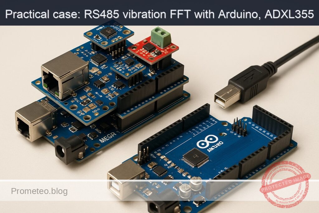
Advanced Hands‑On: FFT Vibration Monitor over RS‑485 with Arduino Mega 2560, Ethernet Shield W5500, ADXL355, and MAX485
This advanced practical case builds a robust vibration monitor that acquires high‑resolution acceleration data from an ADXL355 (SPI), computes an FFT on the Arduino Mega 2560, and publishes the results over an RS‑485 bus using a MAX485 transceiver. The W5500 Ethernet Shield is used to verify SPI bus sharing and optionally stream summaries over UDP for lab validation. The focus is on the objective: fft-vibration-monitor-rs485.
You will sample one axis at a precise rate, window the data, compute the FFT (N=256), extract the top spectral peaks, compute RMS, and transmit compact ASCII summaries over RS‑485. You’ll also learn how to share the SPI bus between W5500 and ADXL355 safely using SPI transactions on the Mega.
Prerequisites
- Operating system:
- Linux (Ubuntu 20.04+), macOS (12+), or Windows 10/11
- Arduino CLI installed and available in PATH
- Confirm with:
arduino-cli version - Recommended Arduino CLI: 0.34.0 or newer
- A serial terminal capable of 115200 bps (e.g.,
arduino-cli monitor,screen, PuTTY) - Optional for validation:
- Python 3.8+ for a minimal RS‑485/UDP receiver script
- USB driver notes for Arduino Mega 2560:
- Official Mega 2560: uses ATmega16U2 (no additional drivers on macOS/Linux; Windows uses built-in driver)
- Many Mega 2560 clones: CH340/CH34x USB-UART bridge; install CH34x driver if your OS does not recognize the board
Materials (Exact Model)
- Arduino Mega 2560 R3 (ATmega2560)
- Ethernet Shield W5500 (Arduino Ethernet Shield 2 or a W5500-compatible shield)
- ADXL355 (3-axis, low-noise digital accelerometer; SPI mode)
- Use a breakout/eval board with access to SCLK/MOSI/MISO/CS
- Mandatory: logic level shifter for 5V↔3.3V (bidirectional, e.g., BSS138-based or TXB0104/0108)
- MAX485 RS‑485 transceiver module (5V)
- Power: USB 5V from PC or a regulated 5V supply for standalone operation
- RS‑485 twisted-pair cable, 120 Ω termination resistor (if your RS‑485 network segment requires it)
- Optional: USB‑RS485 dongle for PC validation
- Jumper wires, breadboard or terminal blocks
Setup/Connection
The system uses two SPI devices (W5500 and ADXL355) and one UART (RS‑485 via MAX485). The Mega 2560 and W5500 shield share the SPI bus on the ICSP header; each device must have a distinct CS pin and never be simultaneously selected. ADXL355 is a 3.3V-only device and requires a level shifter for SCLK, MOSI, CS (and ideally MISO protection). The MAX485 runs at 5V and connects to Serial1.
Key guidelines:
– Keep W5500 CS (D10) high when ADXL355 is selected. Keep ADXL355 CS high when Ethernet is active.
– SPI transactions isolate clock mode and speed for each device.
– Drive pin 10 (W5500 CS) as OUTPUT at all times on the Mega to prevent unintended SPI bus interference.
– Ensure the ADXL355 sees clean 3.3V power and 3.3V logic levels.
– Use termination and biasing per RS‑485 best practices.
Pin/Signal Mapping Table
| Function | Board/Shield Pin | External Device Pin | Notes |
|---|---|---|---|
| SPI SCK | Mega ICSP SCK | ADXL355 SCLK | Through 3.3V level shifter |
| SPI MOSI | Mega ICSP MOSI | ADXL355 SDI (MOSI) | Through 3.3V level shifter |
| SPI MISO | Mega ICSP MISO | ADXL355 SDO (MISO) | Use 3.3V-to-5V safe path; level shifter or direct if 5V-tolerant (ADXL355 is not 5V tolerant; isolate) |
| ADXL355 CS | Mega D9 | ADXL355 CS | Through 3.3V level shifter; default HIGH (inactive) |
| 3.3V | Mega 3.3V | ADXL355 VCC | Power for ADXL355 |
| GND | Mega GND | ADXL355 GND | Common ground |
| W5500 CS | Mega D10 | W5500 CS (on shield) | Controlled by Ethernet library |
| SPI bus | Mega ICSP header | W5500 | Shield stacking uses ICSP |
| RS‑485 DI | Mega TX1 (D18) | MAX485 DI | UART TX to transceiver |
| RS‑485 RO | Mega RX1 (D19) | MAX485 RO | UART RX from transceiver |
| RS‑485 DE/RE | Mega D2 | MAX485 DE+RE (tied) | HIGH=transmit, LOW=receive |
| 5V | Mega 5V | MAX485 VCC | Power for MAX485 module |
| GND | Mega GND | MAX485 GND | Common ground |
| RS‑485 A/B | — | MAX485 A/B | Twisted pair bus; 120 Ω termination at ends only |
Notes:
– Many W5500 shields also break out an SD card on D4; keep D4 as OUTPUT/HIGH (not selected) if not using SD.
– Ensure bias resistors (pull-up on A, pull-down on B) are present somewhere on the RS‑485 network if the bus can idle floating. Many modules include them; verify.
Full Code (Arduino Mega 2560)
The sketch performs:
– SPI setup for W5500 and ADXL355 with distinct CS lines
– ADXL355 initialization over SPI (standby, ODR configuration, measurement mode)
– Time-domain acquisition at 1000 Hz for 256 samples (Z axis by default)
– Windowing + FFT (ArduinoFFT) and extraction of top 5 peaks
– RMS calculation (time-domain)
– RS‑485 ASCII summary frames via Serial1 with DE/RE pin control
– Optional UDP broadcast of the summary (Ethernet)
Important: ADXL355 register map here targets a common configuration. If your module differs, verify the register addresses in the ADXL355 datasheet. The identity registers are used to validate the device.
/*
  fft-vibration-monitor-rs485
  Board: Arduino Mega 2560 (ATmega2560)
  Peripherals: Ethernet Shield W5500 (CS=D10), ADXL355 (SPI, CS=D9, 3.3V), MAX485 (RS-485 via Serial1)
  Sampling: 1000 Hz, N=256, single axis (Z)
  Output: RS-485 ASCII summary lines; optional UDP broadcast

  Libraries required:
    - Ethernet (for W5500)
    - arduinoFFT (for FFT)
  Install via Arduino CLI:
    arduino-cli lib install "Ethernet" "ArduinoFFT"
*/

#include <SPI.h>
#include <Ethernet.h>
#include <EthernetUdp.h>
#include <arduinoFFT.h>

// -------------------- Configurable constants --------------------
static const uint16_t SAMPLES = 256;            // FFT size
static const double SAMPLING_FREQUENCY = 1000;  // Hz
static const uint8_t RS485_DIR_PIN = 2;         // DE+RE tied to D2
static const uint8_t ADXL355_CS_PIN = 9;        // Chip Select for ADXL355
static const uint8_t W5500_CS_PIN  = 10;        // CS for W5500 (shield default)
static const bool    ENABLE_UDP    = true;      // Optional UDP summary
static const uint16_t UDP_PORT     = 5055;      // UDP port for summaries

// Ethernet configuration (set to your LAN; consider DHCP if needed)
byte mac[] = { 0x02, 0x98, 0xEF, 0x35, 0x55, 0x01 };
IPAddress ip(192, 168, 1, 200);
IPAddress dns(192, 168, 1, 1);
IPAddress gateway(192, 168, 1, 1);
IPAddress subnet(255, 255, 255, 0);

// -------------------- FFT buffers --------------------
double vReal[SAMPLES];
double vImag[SAMPLES];
arduinoFFT FFT(vReal, vImag, SAMPLES, SAMPLING_FREQUENCY);

// -------------------- UDP --------------------
EthernetUDP Udp;

// -------------------- ADXL355 register map (subset) --------------------
// Refer to ADXL355 datasheet to confirm these addresses
// Identity registers
#define ADXL355_REG_DEVID_AD   0x00 // Expected 0xAD
#define ADXL355_REG_DEVID_MST  0x01 // Expected 0x1D
#define ADXL355_REG_PARTID     0x02 // Expected 0xED
#define ADXL355_REG_REVID      0x03
#define ADXL355_REG_STATUS     0x04
// Data registers (X/Y/Z each 20-bit: 3 bytes each)
#define ADXL355_REG_XDATA3     0x08
#define ADXL355_REG_YDATA3     0x0B
#define ADXL355_REG_ZDATA3     0x0E
// Control/config
#define ADXL355_REG_FILTER     0x28 // ODR/LPF config
#define ADXL355_REG_RANGE      0x2C // Range: ±2g/±4g/±8g
#define ADXL355_REG_POWER_CTL  0x2D // Measurement mode control
// SPI R/W bits for address
#define ADXL355_SPI_READ       0x01
#define ADXL355_SPI_WRITE      0x00
#define ADXL355_SPI_MB         0x02 // Multiple-byte access

// Sensitivity for ±2g range (verify if you change range)
// ADXL355 typical: 256000 LSB/g at ±2g
static const double ADXL355_LSB_PER_G = 256000.0;

// SPI settings per device
SPISettings settingsADXL355(4000000, MSBFIRST, SPI_MODE0);
SPISettings settingsW5500(14000000, MSBFIRST, SPI_MODE0);

// -------------------- Utility: RS-485 Direction Control --------------------
void rs485SetTransmit(bool enable) {
  digitalWrite(RS485_DIR_PIN, enable ? HIGH : LOW);
}

// -------------------- SPI low-level for ADXL355 --------------------
uint8_t adxl355ReadReg(uint8_t reg) {
  uint8_t val = 0;
  SPI.beginTransaction(settingsADXL355);
  digitalWrite(ADXL355_CS_PIN, LOW);
  // For ADXL355 SPI: set R/W bit to 1 for read; multi-byte bit as 0 here
  SPI.transfer((reg << 1) | ADXL355_SPI_READ);
  val = SPI.transfer(0x00);
  digitalWrite(ADXL355_CS_PIN, HIGH);
  SPI.endTransaction();
  return val;
}

void adxl355WriteReg(uint8_t reg, uint8_t value) {
  SPI.beginTransaction(settingsADXL355);
  digitalWrite(ADXL355_CS_PIN, LOW);
  SPI.transfer((reg << 1) | ADXL355_SPI_WRITE);
  SPI.transfer(value);
  digitalWrite(ADXL355_CS_PIN, HIGH);
  SPI.endTransaction();
}

// Burst read 3 bytes from X/Y/Z data start register
void adxl355Read3(uint8_t startReg, uint8_t* b0, uint8_t* b1, uint8_t* b2) {
  SPI.beginTransaction(settingsADXL355);
  digitalWrite(ADXL355_CS_PIN, LOW);
  SPI.transfer((startReg << 1) | ADXL355_SPI_READ | ADXL355_SPI_MB);
  *b0 = SPI.transfer(0x00);
  *b1 = SPI.transfer(0x00);
  *b2 = SPI.transfer(0x00);
  digitalWrite(ADXL355_CS_PIN, HIGH);
  SPI.endTransaction();
}

// Convert 20-bit two's complement (from bytes [MSB..LSB], top 20 bits) to signed 32-bit
int32_t adxl355_u20_to_s32(uint8_t b2, uint8_t b1, uint8_t b0) {
  // Data: [b2: MSB][b1][b0: upper 4 bits], lower 4 bits in b0 are not part of 20-bit data
  int32_t raw20 = ((int32_t)b2 << 12) | ((int32_t)b1 << 4) | ((int32_t)(b0 >> 4) & 0x0F);
  // Sign-extend 20-bit
  if (raw20 & 0x80000) {
    raw20 |= 0xFFF00000;
  }
  return raw20;
}

// Read Z-axis in g (double)
double adxl355ReadZ_g() {
  uint8_t b2 = 0, b1 = 0, b0 = 0;
  adxl355Read3(ADXL355_REG_ZDATA3, &b2, &b1, &b0);
  int32_t raw = adxl355_u20_to_s32(b2, b1, b0);
  return (double)raw / ADXL355_LSB_PER_G;
}

bool adxl355Init(uint16_t odrCode /*0..9 approx*/) {
  // Verify identity
  uint8_t id_ad = adxl355ReadReg(ADXL355_REG_DEVID_AD);
  uint8_t id_mst = adxl355ReadReg(ADXL355_REG_DEVID_MST);
  uint8_t id_part = adxl355ReadReg(ADXL355_REG_PARTID);

  Serial.print(F("ADXL355 IDs: AD=0x")); Serial.print(id_ad, HEX);
  Serial.print(F(" MST=0x")); Serial.print(id_mst, HEX);
  Serial.print(F(" PART=0x")); Serial.println(id_part, HEX);

  if (id_ad != 0xAD || id_part != 0xED) {
    Serial.println(F("ERROR: ADXL355 identity mismatch."));
    return false;
  }

  // Put device in standby before changing config (POWER_CTL: set MEAS=0)
  // POWER_CTL bits: 0x01=Temperature; 0x02=Standby? For ADXL355, MEAS bit is 0=standby, 1=measure (verify datasheet).
  // We write 0x00 to ensure standby.
  adxl355WriteReg(ADXL355_REG_POWER_CTL, 0x00);

  // Configure ODR/LPF (FILTER reg). For many ADXL355 configs: ODR = 4000 / 2^odrCode
  // To get ~1000 Hz, set odrCode=2 (4000/4=1000)
  uint8_t filterVal = (odrCode & 0x0F); // HPF disabled
  adxl355WriteReg(ADXL355_REG_FILTER, filterVal);

  // Range default is ±2g; leave RANGE untouched for best sensitivity.
  // Switch to measurement mode (MEAS=1)
  adxl355WriteReg(ADXL355_REG_POWER_CTL, 0x06); // 0x06 commonly used to enable measurement + temp; adjust if needed

  delay(10);
  return true;
}

// -------------------- Helpers: Window, RMS, Peak Detection --------------------
double computeRMS(const double* arr, uint16_t n) {
  double acc = 0.0;
  for (uint16_t i = 0; i < n; i++) {
    acc += arr[i] * arr[i];
  }
  return sqrt(acc / (double)n);
}

struct Peak {
  double freq;
  double mag;
};

void findTopPeaks(const double* mag, uint16_t n, double fs, Peak* peaks, uint8_t k) {
  // naive selection of top k magnitudes (excluding DC at bin 0)
  for (uint8_t i = 0; i < k; i++) { peaks[i].freq = 0; peaks[i].mag = 0; }
  for (uint16_t bin = 1; bin < n/2; bin++) {
    double m = mag[bin];
    // insert into peaks if higher than current min
    int idxMin = 0;
    for (uint8_t j = 1; j < k; j++) if (peaks[j].mag < peaks[idxMin].mag) idxMin = j;
    if (m > peaks[idxMin].mag) {
      peaks[idxMin].mag = m;
      peaks[idxMin].freq = (double)bin * fs / (double)n;
    }
  }
  // simple sort by descending magnitude (bubble for small k)
  for (uint8_t i = 0; i < k; i++) {
    for (uint8_t j = i + 1; j < k; j++) {
      if (peaks[j].mag > peaks[i].mag) {
        Peak tmp = peaks[i]; peaks[i] = peaks[j]; peaks[j] = tmp;
      }
    }
  }
}

// -------------------- Setup & Loop --------------------
void setup() {
  pinMode(W5500_CS_PIN, OUTPUT);
  digitalWrite(W5500_CS_PIN, HIGH); // deselect W5500
  pinMode(ADXL355_CS_PIN, OUTPUT);
  digitalWrite(ADXL355_CS_PIN, HIGH); // deselect ADXL355
  pinMode(RS485_DIR_PIN, OUTPUT);
  rs485SetTransmit(false);

  Serial.begin(115200);  // USB debug
  while (!Serial) { ; }

  Serial1.begin(115200); // RS-485 UART (via MAX485)
  delay(50);

  SPI.begin();

  // Initialize Ethernet (W5500)
  Ethernet.init(W5500_CS_PIN);
  Ethernet.begin(mac, ip, dns, gateway, subnet);
  delay(300);
  IPAddress myIP = Ethernet.localIP();
  Serial.print(F("Ethernet IP: "));
  Serial.println(myIP);
  if (ENABLE_UDP) {
    if (Udp.begin(UDP_PORT)) {
      Serial.print(F("UDP listening on port ")); Serial.println(UDP_PORT);
    } else {
      Serial.println(F("UDP begin failed; continuing without UDP."));
    }
  }

  // Initialize ADXL355 for ~1000 Hz ODR code 2
  if (!adxl355Init(2)) {
    Serial.println(F("ADXL355 init failed. Check wiring/level shifting."));
  } else {
    Serial.println(F("ADXL355 initialized."));
  }

  Serial.println(F("Setup done."));
}

void loop() {
  // Acquire SAMPLES at SAMPLING_FREQUENCY
  const uint32_t usPerSample = (uint32_t)(1000000.0 / SAMPLING_FREQUENCY);
  uint32_t tStart = micros();
  double mean = 0.0;

  for (uint16_t i = 0; i < SAMPLES; i++) {
    // Wait until next sample time
    while ((micros() - tStart) < usPerSample * i) { /* spin */ }
    // Read Z-axis in g
    double g = adxl355ReadZ_g();
    vReal[i] = g;
    vImag[i] = 0.0;
    mean += g;
  }
  mean /= (double)SAMPLES;

  // Remove DC offset
  for (uint16_t i = 0; i < SAMPLES; i++) {
    vReal[i] -= mean;
  }

  // Compute RMS in time domain after DC removal
  double rms_g = computeRMS(vReal, SAMPLES);

  // Windowing + FFT
  FFT.Windowing(vReal, SAMPLES, FFT_WIN_TYP_HAMMING, FFT_FORWARD);
  FFT.Compute(vReal, vImag, SAMPLES, FFT_FORWARD);
  FFT.ComplexToMagnitude(vReal, vImag, SAMPLES); // vReal now holds magnitudes

  // Detect top 5 peaks
  Peak peaks[5];
  findTopPeaks(vReal, SAMPLES, SAMPLING_FREQUENCY, peaks, 5);

  // Compose ASCII summary line (RS-485 and UDP)
  static uint32_t seq = 0;
  char line[512];
  // Format: FFT_SUMMARY seq=<n> fs=1000.00Hz n=256 rms_g=<val> peaks=[f1:mag1;f2:mag2;...]
  int len = snprintf(line, sizeof(line),
                     "FFT_SUMMARY seq=%lu fs=%.2fHz n=%u rms_g=%.6f peaks=["
                     "%.2f:%.6f; %.2f:%.6f; %.2f:%.6f; %.2f:%.6f; %.2f:%.6f]\r\n",
                     (unsigned long)seq++,
                     SAMPLING_FREQUENCY, SAMPLES, rms_g,
                     peaks[0].freq, peaks[0].mag,
                     peaks[1].freq, peaks[1].mag,
                     peaks[2].freq, peaks[2].mag,
                     peaks[3].freq, peaks[3].mag,
                     peaks[4].freq, peaks[4].mag);

  // Send over RS-485
  rs485SetTransmit(true);
  delayMicroseconds(20);        // allow driver to enable
  Serial1.write((const uint8_t*)line, len);
  Serial1.flush();
  delayMicroseconds(50);        // ensure last byte has left the UART/driver
  rs485SetTransmit(false);

  // Optional UDP broadcast (replace broadcast IP as needed)
  if (ENABLE_UDP) {
    IPAddress bcast = IPAddress(ip[0], ip[1], ip[2], 255);
    Udp.beginPacket(bcast, UDP_PORT);
    Udp.write((const uint8_t*)line, len);
    Udp.endPacket();
  }

  // Local debug (USB)
  Serial.print(line);

  // Short pacing delay to avoid continuous saturation
  delay(50);
}
Implementation notes:
– The ADXL355 register definitions and POWER_CTL settings are typical. If your module reports incorrect IDs or no data, verify the ADXL355 SPI address convention and control bits against the datasheet of the exact revision you have.
– We used a Hamming window from ArduinoFFT to reduce spectral leakage. The bin amplitudes reported by FFT.ComplexToMagnitude are unitless relative magnitudes; use calibration to convert to physical units if you need absolute spectral density.
– We used Z axis to simplify wiring. You can switch to X/Y by reading from ADXL355_REG_XDATA3/YDATA3.
Build, Flash, and Run (Arduino CLI, Mega 2560)
Use the Arduino CLI and the AVR core for Mega 2560. Replace the serial port with your actual device (Linux: /dev/ttyACM0 or /dev/ttyUSB0; macOS: /dev/tty.usbmodemXXXX; Windows: COM5, etc.).
arduino-cli core update-index
arduino-cli core install arduino:avr

# 2) (Optional) Create project folder
PROJECT_DIR="$HOME/fft-vibration-monitor-rs485"
mkdir -p "$PROJECT_DIR"
# Save the above sketch as "$PROJECT_DIR/fft_vibe_rs485.ino"

# 3) Install libraries
arduino-cli lib install "ArduinoFFT" "Ethernet"

# 4) Compile for Arduino Mega 2560 (FQBN: arduino:avr:mega)
arduino-cli compile --fqbn arduino:avr:mega "$PROJECT_DIR"

# 5) Upload (replace the serial port with yours)
# Linux/macOS example:
arduino-cli upload -p /dev/ttyACM0 --fqbn arduino:avr:mega "$PROJECT_DIR"
# Windows example:
# arduino-cli upload -p COM5 --fqbn arduino:avr:mega "%USERPROFILE%\fft-vibration-monitor-rs485"

# 6) Open a serial monitor for debug output (USB)
arduino-cli monitor -p /dev/ttyACM0 -c baudrate=115200
If you stacked the W5500 shield, ensure the Mega enumerates as expected and the LEDs on the Ethernet jack show link/activity.
Step‑by‑Step Validation
Follow these steps in order, verifying each before moving forward.
1) SPI and Ethernet sanity check
- Power the Mega with the W5500 shield stacked; connect an Ethernet cable to your LAN.
- Open the serial monitor at 115200 bps.
- On reset, you should see:
- “Ethernet IP: 192.168.1.200” (or your configured IP)
- “UDP listening on port 5055” if UDP is enabled
- If DHCP is preferred, change the Ethernet.begin() call to
Ethernet.begin(mac)and ensure your LAN issues a lease. Update the UDP broadcast IP if necessary.
2) ADXL355 identity verification
- The serial log prints: “ADXL355 IDs: AD=0xAD MST=0x1D PART=0xED”
- If the IDs do not match:
- Check level shifting on all SPI lines. ADXL355 must not see 5V logic.
- Ensure ADXL355 CS (D9) is HIGH when not selected, and W5500 CS (D10) stays HIGH while accessing ADXL355.
- Confirm the SPI mode (MODE0) and a conservative speed (we use 4 MHz).
3) Baseline acceleration and sample rate
- With the sensor stationary, observe the RMS value in the summary line:
- Example: “rms_g=0.0012” to “0.0050” g depending on noise.
- The output lines should appear every ~350–500 ms (acquire + FFT + reporting).
- If you see erratic bursts:
- Reduce Ethernet activity (disable UDP by setting ENABLE_UDP=false).
- Confirm that SPI bus CS lines are never asserted simultaneously.
4) FFT observation with a known vibration
- Use a calibration source:
- Smartphone “tone generator” or “vibration” app. Place the sensor on the phone’s back and generate a sine tone with the phone’s speaker at 150 Hz; or use a small shaker if available.
- Expected result:
- The “peaks” list should show a dominant frequency near 150 Hz, e.g., “peaks=[150.39:1.234000; 300.78:0.120000; …]”
- The second harmonic may appear (around 2× the fundamental) depending on the source.
- If your tone is outside the Nyquist frequency (fs/2 = 500 Hz), increase SAMPLING_FREQUENCY and adjust the FILTER ODR code to match, or keep your excitation under 500 Hz.
5) RS‑485 link validation (PC receiver)
- Connect MAX485 A/B to a USB‑RS485 adapter on your PC (A↔A, B↔B). Ensure the RS‑485 bus has proper termination at the ends.
- On the PC, run a simple receiver. Example Python 3 script:
# recv_rs485_udp.py - minimal RS-485 (via USB serial) and UDP listener
import sys, socket, serial, threading

def serial_reader(port, baud=115200):
    try:
        with serial.Serial(port, baudrate=baud, timeout=1) as ser:
            print(f"[SER] Listening on {port} @ {baud}...")
            while True:
                line = ser.readline().decode(errors='ignore').strip()
                if line:
                    print(f"[RS485] {line}")
    except Exception as e:
        print(f"[SER] {e}")

def udp_listener(port=5055, bind_ip='0.0.0.0'):
    sock = socket.socket(socket.AF_INET, socket.SOCK_DGRAM)
    sock.bind((bind_ip, port))
    print(f"[UDP] Listening on {bind_ip}:{port} ...")
    while True:
        data, addr = sock.recvfrom(2048)
        print(f"[UDP] {addr}: {data.decode(errors='ignore').strip()}")

if __name__ == "__main__":
    if len(sys.argv) < 2:
        print("Usage: python recv_rs485_udp.py <serial_port> [udp_port]")
        sys.exit(1)
    port = sys.argv[1]
    udp_port = int(sys.argv[2]) if len(sys.argv) > 2 else 5055
    threading.Thread(target=serial_reader, args=(port,), daemon=True).start()
    udp_listener(udp_port)
- Run it (replace the serial device with your adapter):
- Linux:
python3 recv_rs485_udp.py /dev/ttyUSB0 5055 - Windows:
python recv_rs485_udp.py COM7 5055 - You should see lines like:
[RS485] FFT_SUMMARY seq=123 fs=1000.00Hz n=256 rms_g=0.003215 peaks=[...[UDP] ('192.168.1.200', 5055): FFT_SUMMARY seq=...
6) Signal sanity and spectral leakage
- Try wide-band excitation (tapping the table) and observe a distributed spectrum.
- Try a steadier mechanical vibration and check that the peak narrows and stabilizes.
- Change the window type (e.g., to Hanning) by replacing FFT_WIN_TYP_HAMMING if needed to test leakage performance.
Troubleshooting
- ADXL355 returns wrong IDs or all zeros:
- Likely level shifting or CS contention problem. Verify 3.3V VCC and ensure logic level shifter orientation is correct. Confirm CS lines: D9 to ADXL355, D10 to W5500. Drive both CS lines HIGH on boot. Use SPI transactions.
-
Reduce SPI speed to 1 MHz for initial bring-up:
SPISettings(1000000, MSBFIRST, SPI_MODE0). -
FFT appears noisy or peaks are unstable:
- Ensure rigid mechanical coupling to the vibration source.
- Remove DC offset as already shown; verify the means are near zero before windowing.
-
Increase sample size to 512 (only if memory allows): Beware Mega’s 8 KB SRAM. 512 samples may push limits once buffers and Ethernet are active. Test carefully.
-
RS‑485 has framing errors, missing lines, or gibberish:
- Confirm your MAX485 DE/RE control timing. We set a short delay before and after sending to guarantee driver turnaround. Increase delays slightly if your module needs it.
- Verify matching baud rate on both ends (115200 8N1).
-
Check bus termination (120 Ω at ends only) and bias resistors (to define idle state).
-
W5500/Ethernet blocks ADXL355 SPI transfers:
- Always use SPI transactions and explicitly assert the correct CS line. Do not let both CS pins be LOW at the same time.
-
Keep pin 10 as OUTPUT to avoid putting the Mega’s SPI into slave mode inadvertently.
-
UDP not received on PC:
- Make sure the PC is in the same subnet and not blocking incoming UDP on the chosen port.
-
Adjust broadcast IP to your network (e.g., 192.168.0.255). Alternatively, unicast to a specific host IP.
-
Sample rate drifts:
- The current loop is timed via micros(). For higher precision, use a hardware timer interrupt to trigger sampling. Keep SPI operations short.
Improvements
- Sampling accuracy and throughput:
- Replace the micros()-based loop with a Timer1 Compare Match ISR at 1 kHz. In the ISR, only trigger a flag and read the sample in the main loop or use double buffering to avoid long SPI operations inside ISRs.
-
Explore averaging or decimation filters to reduce noise.
-
Multi-axis FFT:
-
Collect X, Y, Z simultaneously (burst read 9 bytes). Run FFTs per axis or compute vector magnitude before FFT (note: nonlinear operation may smear spectral content).
-
RS‑485 protocol:
- Wrap ASCII frames in a simple framing with STX/ETX or use a CRC-16 (Modbus-like) for robust multi-drop scenarios.
-
Implement a command channel over RS‑485 to adjust sampling frequency, FFT size, and reporting interval remotely.
-
Ethernet monitoring:
- Serve a simple HTTP/JSON endpoint for the latest FFT summary using EthernetServer.
-
Use DHCP with a fallback to static IP if DHCP fails.
-
Data logging:
-
Stream summaries to a central logger, or log raw frames to SD (D4 CS, ensure it remains deselected when unused).
-
Calibration:
- Use gravity-based calibration to map raw g units precisely (offset, scale per axis).
- Compute and display noise spectral density (g/√Hz) after calibration.
Final Checklist
- Hardware
- Arduino Mega 2560 stacked with W5500 shield
- ADXL355 powered at 3.3V with proper 3.3V level shifting on SPI lines
- MAX485 wired to Serial1 (TX1=18, RX1=19), DE/RE tied to D2
- RS‑485 A/B twisted pair with 120 Ω termination at the ends only
-
Common grounds between all modules
-
Software
- Arduino CLI installed and on PATH
- Core installed: arduino:avr
- Libraries installed: ArduinoFFT, Ethernet
- Project compiled with FQBN arduino:avr:mega
-
Uploaded to the correct serial port
-
Configuration
- ADXL355 CS on D9; W5500 CS on D10
- SPI transactions used with distinct settings for ADXL355 and W5500
- Sampling: 1000 Hz, N=256 (fits Mega 2560 SRAM)
-
RS‑485: 115200 bps, ASCII summaries, DE/RE control verified
-
Validation
- Serial log shows Ethernet IP and ADXL355 IDs (0xAD and 0xED)
- Stationary RMS small (~0.001–0.005 g typical)
- Known vibration (e.g., ~150 Hz) produces a clear spectral peak
- RS‑485 receiver (USB‑RS485) displays summary lines reliably
- Optional UDP summaries received on the LAN
By completing this project, you’ve implemented a full vibration acquisition and spectral analysis pipeline on the Arduino Mega 2560, safely shared the SPI bus between W5500 and ADXL355, and published compact, actionable results over an industrial RS‑485 link.
Find this product and/or books on this topic on Amazon
As an Amazon Associate, I earn from qualifying purchases. If you buy through this link, you help keep this project running.
Quick Quiz

Telecommunications Electronics Engineer and Computer Engineer (official degrees in Spain).

