Objective and use case
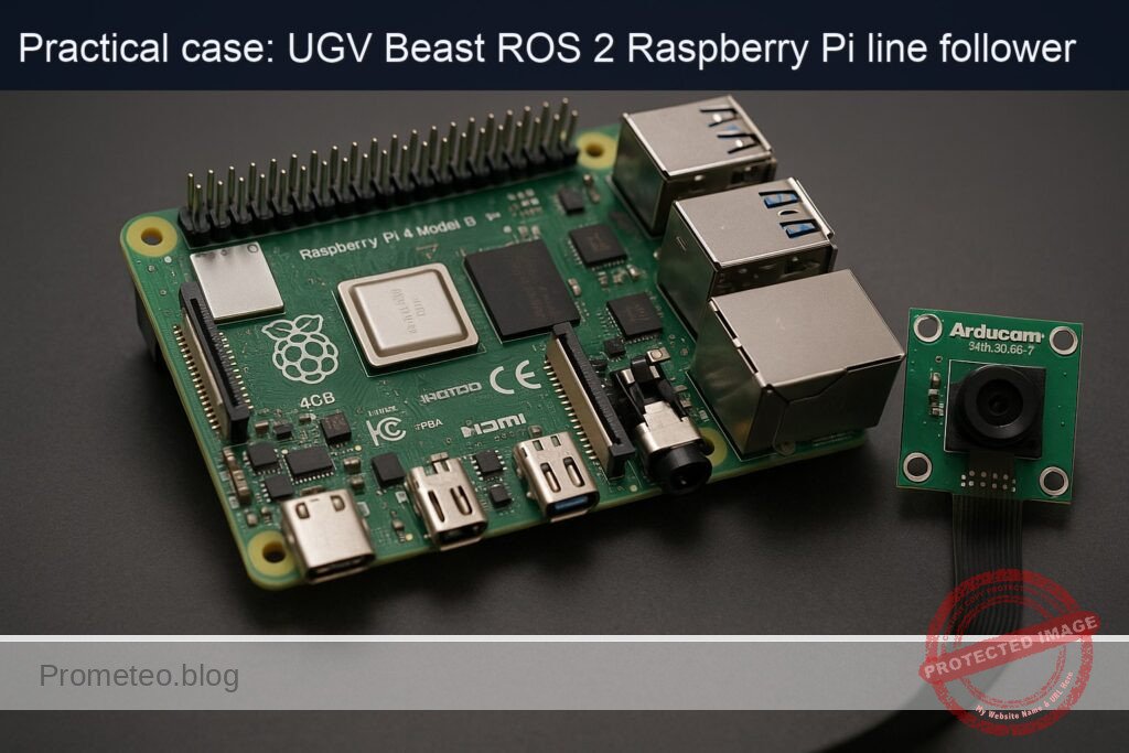
What you’ll build: A ROS 2 Humble line-follower running on a Raspberry Pi 4 (4GB) with an Arducam 5MP OV5647 camera, detecting a black tape line on a light floor and publishing wheel commands to follow it autonomously at 15–25 FPS.
Why it matters / Use cases
- Warehouse path guidance: Use black or colored tape to guide low-cost UGV carts along fixed routes between racks and docks, avoiding LiDAR (often >$1,000) while maintaining <5 cm lateral error at 0.5–0.8 m/s.
- Teaching ROS 2 perception + control: Demonstrates the full pipeline—camera → image processing → /cmd_vel → wheel motion—so students can visualize topics, QoS, and controller effects in real time at ~20 FPS.
- Repeatable lab experiments: A known, repeatable track allows benchmarking motor calibration, odometry drift, and PID gains with metrics like RMS cross-track error and average tracking latency (<120 ms).
- Fallback navigation mode: In GPS- or LiDAR-degraded areas (reflective floors, glass walls), a tape-guided mode keeps robots moving safely along pre-approved paths with predictable behavior.
- Production line material handling: Enables simple tugger or cart robots to shuttle bins between stations over fixed tape paths, sustaining multi-hour shifts on a Pi 4 at <40% CPU and <30% GPU load (using hardware-accelerated image processing).
Expected outcome
- A working ROS 2 node that subscribes to the Arducam image topic, thresholds the line, computes an error signal, and publishes /cmd_vel at 20–30 Hz.
- Stable line following on a taped track at 0.3–0.7 m/s with <10 cm steady-state cross-track error and <150 ms end-to-end perception-to-command latency.
- Verified real-time performance on Raspberry Pi 4: 15–25 FPS processing with <60% CPU usage and <35% memory usage while logging ROS 2 topics.
- Reusable launch files and parameters (camera resolution, ROI, thresholds, PID gains) to adapt the same stack to different line colors, lighting, and UGV platforms.
Audience: Robotics hobbyists, students, and engineers familiar with Linux who want a practical ROS 2 perception+control project; Level: Intermediate (comfortable with ROS 2 basics and Python or C++).
Architecture/flow: Arducam node publishes /image_raw → custom line-follower node subscribes, preprocesses (grayscale, blur, threshold, centroid) → computes lateral error and heading → PID or PD controller generates linear/angular velocity → controller publishes /cmd_vel → ROS 2 diff-drive or motor driver node converts /cmd_vel to wheel commands and drives the UGV.
Prerequisites
- OS on RPi: Ubuntu Server 22.04 64‑bit (aarch64) installed and booting on the Raspberry Pi 4.
- ROS 2: ROS 2 Humble installed via
apton the Pi. - Headless operation: SSH access to the Pi; no GUI assumed.
- Networking: RPi on the same network as your development PC (optional but useful for RViz on the PC).
- Basic skills:
- Comfortable with Linux terminal.
- Basic Python programming.
- Familiarity with ROS 2 packages, topics, and launch files.
Materials
| Item type | Exact model / name | Notes |
|---|---|---|
| SBC | Raspberry Pi 4 Model B 4GB | aarch64, Ubuntu 22.04 |
| Camera | Arducam 5MP OV5647 Camera Module | CSI‑2 ribbon to Pi camera connector |
| Robot base (UGV) | UGV Beast (ROS 2) – RPi platform (with motors + drivers) | Differential drive |
| MicroSD card | ≥32 GB Class 10 | Ubuntu 22.04 64‑bit |
| Power | 5 V / 3 A USB‑C supply + battery pack / DC supply | For robot motion |
| Cables | CSI ribbon for camera, motor power wires, USB (if needed) | Depend on base |
| Network | Ethernet cable or Wi‑Fi configured on Ubuntu | For SSH and RViz |
| Floor line | 2–3 cm wide black electrical tape on light floor | Closed loop or long straight |
Setup / Connection
1. Physical connections
- Mount the camera
- Power off the Raspberry Pi.
- Connect the Arducam 5MP OV5647 Camera Module to the CSI camera connector on the Pi:
- Lift the connector latch.
- Insert the ribbon cable with the metal contacts facing the HDMI ports.
- Close the latch to lock the cable.
-
Fix the camera so it points downwards at the floor, about 15–30 cm above the line.
-
Connect the motors and drivers (UGV Beast base)
- Ensure your UGV Beast base has:
- Left and right DC motors connected to a motor driver (H‑bridge / motor controller).
- Motor driver controlled by the Raspberry Pi via GPIO/PWM or via an existing microcontroller/driver board exposed as a ROS 2 hardware interface.
- This tutorial assumes:
- You have a ROS 2 hardware interface (e.g., custom
ros2_controlhardware plugin) already integrated in the UGV Beast firmware, exposing joint interfaces. - The robot moves correctly when commands are sent to
/cmd_velthroughdiff_drive_controller.
- You have a ROS 2 hardware interface (e.g., custom
If you do not have this, you can still complete all line‑detection steps; your validation will be on logged /cmd_vel instead of actual motions.
- Power and network
- Power the Raspberry Pi with a reliable 5 V / 3 A source.
- Connect via Ethernet or Wi‑Fi (configured in
netplan) from your PC.
2. Raspberry Pi OS & ROS 2 installation
Assuming a fresh Ubuntu 22.04 64‑bit:
sudo apt update
sudo apt upgrade -y
sudo apt install -y build-essential git cmake python3-colcon-common-extensions \
  python3-vcstool python3-rosdep curl

# 2. ROS 2 Humble sources
sudo apt install -y software-properties-common
sudo add-apt-repository universe
sudo add-apt-repository restricted
sudo add-apt-repository multiverse

sudo curl -sSL https://raw.githubusercontent.com/ros/rosdistro/master/ros.key \
  -o /usr/share/keyrings/ros-archive-keyring.gpg

echo "deb [arch=arm64 signed-by=/usr/share/keyrings/ros-archive-keyring.gpg] \
  http://packages.ros.org/ros2/ubuntu $(. /etc/os-release && echo $UBUNTU_CODENAME) main" \
  | sudo tee /etc/apt/sources.list.d/ros2.list > /dev/null

sudo apt update

# 3. ROS 2 Humble desktop & required packages
sudo apt install -y \
  ros-humble-desktop \
  ros-humble-ros2-control \
  ros-humble-diff-drive-controller \
  ros-humble-robot-localization \
  ros-humble-slam-toolbox \
  'ros-humble-nav2*' \
  ros-humble-rviz2

# 4. Environment setup in .bashrc
echo "source /opt/ros/humble/setup.bash" >> ~/.bashrc
source ~/.bashrc

# 5. Initialize rosdep
sudo rosdep init || true
rosdep update
Workspace and package structure
1. Create the colcon workspace
mkdir -p ~/ros2_ws/src
cd ~/ros2_ws
2. Create a ROS 2 package for the UGV Beast line follower
We’ll create a Python package named ugv_beast_line_follower:
cd ~/ros2_ws/src
ros2 pkg create --build-type ament_python ugv_beast_line_follower \
  --dependencies rclpy sensor_msgs geometry_msgs std_msgs nav_msgs \
  tf2_ros tf2_geometry_msgs
This will create ~/ros2_ws/src/ugv_beast_line_follower.
You’ll add:
- URDF and
ros2_controlconfiguration. - A Python line follower node.
- Launch files.
Robot modeling (URDF + ros2_control)
1. Create URDF file
Create a urdf directory and a minimal URDF with a differential drive and camera link.
mkdir -p ~/ros2_ws/src/ugv_beast_line_follower/urdf
nano ~/ros2_ws/src/ugv_beast_line_follower/urdf/ugv_beast.urdf.xacro
Paste:
<?xml version="1.0"?>
<robot name="ugv_beast" xmlns:xacro="http://ros.org/wiki/xacro">

  <!-- Parameters -->
  <xacro:property name="wheel_radius" value="0.05"/>  <!-- 5 cm -->
  <xacro:property name="track_width"  value="0.30"/>  <!-- 30 cm between wheels -->

  <!-- Base link -->
  <link name="base_link">
    <inertial>
      <origin xyz="0 0 0" rpy="0 0 0"/>
      <mass value="5.0"/>
      <inertia ixx="0.1" ixy="0.0" ixz="0.0"
               iyy="0.1" iyz="0.0"
               izz="0.1"/>
    </inertial>
  </link>

  <!-- Wheels -->
  <link name="left_wheel_link"/>
  <link name="right_wheel_link"/>

  <joint name="left_wheel_joint" type="continuous">
    <origin xyz="0 ${track_width/2} 0" rpy="0 0 0"/>
    <parent link="base_link"/>
    <child link="left_wheel_link"/>
    <axis xyz="0 1 0"/>
  </joint>

  <joint name="right_wheel_joint" type="continuous">
    <origin xyz="0 -${track_width/2} 0" rpy="0 0 0"/>
    <parent link="base_link"/>
    <child link="right_wheel_link"/>
    <axis xyz="0 1 0"/>
  </joint>

  <!-- Camera -->
  <link name="camera_link">
    <visual>
      <geometry>
        <box size="0.02 0.02 0.01"/>
      </geometry>
      <origin xyz="0.1 0 0.15" rpy="0 0 0"/>
    </visual>
  </link>

  <joint name="camera_joint" type="fixed">
    <origin xyz="0.1 0 0.15" rpy="-1.57 0 0"/>
    <parent link="base_link"/>
    <child link="camera_link"/>
  </joint>

</robot>
Calibrating wheel radius and track width
- Wheel radius (
wheel_radius): - Mark a point on the wheel.
- Roll the robot straight for N full wheel rotations while measuring the distance D.
- Compute:
wheel_radius = D / (2 * π * N). - Track width (
track_width): - Command the robot to spin in place by 360°.
- Measure the arc length traveled by one wheel:
L. - Then
track_width ≈ (2 * L) / (2 * π) = L / π.
Update the xacro constants with your measured values.
2. ros2_control configuration
Create config/ros2_control.yaml:
mkdir -p ~/ros2_ws/src/ugv_beast_line_follower/config
nano ~/ros2_ws/src/ugv_beast_line_follower/config/ros2_control.yaml
Example:
controller_manager:
  ros__parameters:
    update_rate: 50

    diff_drive_controller:
      type: diff_drive_controller/DiffDriveController

joint_state_broadcaster:
  ros__parameters:
    type: joint_state_broadcaster/JointStateBroadcaster

diff_drive_controller:
  ros__parameters:
    left_wheel_names:  ["left_wheel_joint"]
    right_wheel_names: ["right_wheel_joint"]

    wheel_separation: 0.30        # track_width (m)
    wheel_radius: 0.05            # wheel radius (m)

    publish_rate: 50.0
    cmd_vel_timeout: 0.5
    use_stamped_vel: false

    enable_odom_tf: true
    odom_frame_id: "odom"
    base_frame_id: "base_link"

    linear:
      x:
        has_velocity_limits: true
        max_velocity: 0.6
        min_velocity: -0.6

    angular:
      z:
        has_velocity_limits: true
        max_velocity: 1.5
        min_velocity: -1.5
This assumes you already have a hardware interface plugin. Plug that configuration into a launch file as needed; for line following we mainly care about publishing to /cmd_vel.
Line follower node implementation
1. Image capture approach
We will use V4L2 so that the camera appears as /dev/video0, and use opencv-python to grab frames in our node. This avoids relying on Pi‑specific camera stacks.
Install dependencies:
sudo apt install -y python3-opencv v4l-utils
Enable and check the camera:
# List V4L2 devices
v4l2-ctl --list-devices
# Test streaming (Ctrl+C to stop) – run this on Pi; if no GUI, just ensure no error
v4l2-ctl --device=/dev/video0 --stream-mmap --stream-count=10
2. Implement the line_follower_node.py
Create the node file:
mkdir -p ~/ros2_ws/src/ugv_beast_line_follower/ugv_beast_line_follower
nano ~/ros2_ws/src/ugv_beast_line_follower/ugv_beast_line_follower/line_follower_node.py
Paste:
#!/usr/bin/env python3
import rclpy
from rclpy.node import Node

import cv2
import numpy as np

from geometry_msgs.msg import Twist


class LineFollowerNode(Node):
    def __init__(self):
        super().__init__("line_follower_node")

        # Parameters
        self.declare_parameter("device_id", 0)
        self.declare_parameter("frame_width", 640)
        self.declare_parameter("frame_height", 480)
        self.declare_parameter("linear_speed", 0.15)
        self.declare_parameter("kp", 0.005)
        self.declare_parameter("kd", 0.001)
        self.declare_parameter("min_area", 500)

        self.device_id = self.get_parameter("device_id").value
        self.frame_width = int(self.get_parameter("frame_width").value)
        self.frame_height = int(self.get_parameter("frame_height").value)
        self.linear_speed = float(self.get_parameter("linear_speed").value)
        self.kp = float(self.get_parameter("kp").value)
        self.kd = float(self.get_parameter("kd").value)
        self.min_area = int(self.get_parameter("min_area").value)

        # Publisher for velocity commands
        self.cmd_pub = self.create_publisher(Twist, "/cmd_vel", 10)

        # Open camera
        self.cap = cv2.VideoCapture(self.device_id)
        if not self.cap.isOpened():
            self.get_logger().error("Could not open camera device /dev/video{}".format(self.device_id))
            raise RuntimeError("Camera open failed")

        # Configure resolution
        self.cap.set(cv2.CAP_PROP_FRAME_WIDTH, self.frame_width)
        self.cap.set(cv2.CAP_PROP_FRAME_HEIGHT, self.frame_height)

        self.prev_error = 0.0

        # Timer to run at ~20Hz
        self.timer = self.create_timer(0.05, self.process_frame)
        self.get_logger().info("Line follower node started")

    def process_frame(self):
        ret, frame = self.cap.read()
        if not ret:
            self.get_logger().warn("Failed to read frame from camera")
            self.stop_robot()
            return

        # Convert to grayscale and blur
        gray = cv2.cvtColor(frame, cv2.COLOR_BGR2GRAY)
        blur = cv2.GaussianBlur(gray, (5, 5), 0)

        # Binary inverse threshold: black line becomes white
        _, binary = cv2.threshold(blur, 0, 255, cv2.THRESH_BINARY_INV + cv2.THRESH_OTSU)

        # Consider only a region of interest at the bottom
        roi_height = int(self.frame_height * 0.3)
        roi = binary[self.frame_height - roi_height : self.frame_height, :]

        # Find contours (white blobs => line)
        contours, _ = cv2.findContours(roi, cv2.RETR_EXTERNAL, cv2.CHAIN_APPROX_SIMPLE)

        if len(contours) == 0:
            self.get_logger().info_throttle(1.0, "No line detected - stopping")
            self.stop_robot()
            return

        # Largest contour assumed to be line
        largest = max(contours, key=cv2.contourArea)
        area = cv2.contourArea(largest)
        if area < self.min_area:
            self.get_logger().info_throttle(1.0, "Line area too small ({}). Stopping.".format(area))
            self.stop_robot()
            return

        # Compute centroid of the contour
        M = cv2.moments(largest)
        if M["m00"] == 0:
            self.get_logger().warn("Zero moment; cannot compute centroid")
            self.stop_robot()
            return

        cx = int(M["m10"] / M["m00"])
        # We only care about x error from image center
        error = cx - (self.frame_width / 2)

        # PD controller for angular velocity
        derivative = error - self.prev_error
        angular_z = -(self.kp * error + self.kd * derivative)
        self.prev_error = error

        twist = Twist()
        twist.linear.x = self.linear_speed
        twist.angular.z = float(angular_z)

        self.cmd_pub.publish(twist)

    def stop_robot(self):
        twist = Twist()
        twist.linear.x = 0.0
        twist.angular.z = 0.0
        self.cmd_pub.publish(twist)

    def destroy_node(self):
        self.stop_robot()
        if self.cap.isOpened():
            self.cap.release()
        super().destroy_node()


def main(args=None):
    rclpy.init(args=args)
    node = LineFollowerNode()
    try:
        rclpy.spin(node)
    except KeyboardInterrupt:
        pass
    finally:
        node.destroy_node()
        rclpy.shutdown()


if __name__ == "__main__":
    main()
Make it executable:
chmod +x ~/ros2_ws/src/ugv_beast_line_follower/ugv_beast_line_follower/line_follower_node.py
3. Package entry point
Edit setup.py:
nano ~/ros2_ws/src/ugv_beast_line_follower/setup.py
Ensure entry_points has:
entry_points={
    'console_scripts': [
        'line_follower_node = ugv_beast_line_follower.line_follower_node:main',
    ],
},
Install package dependencies in package.xml if needed (we already gave them at creation via --dependencies).
Launch file for line follower + URDF
Create a launch file:
mkdir -p ~/ros2_ws/src/ugv_beast_line_follower/launch
nano ~/ros2_ws/src/ugv_beast_line_follower/launch/line_follower.launch.py
Add:
from launch import LaunchDescription
from launch_ros.actions import Node
from launch.actions import DeclareLaunchArgument
from launch.substitutions import LaunchConfiguration

def generate_launch_description():
    device_id = DeclareLaunchArgument(
        "device_id",
        default_value="0",
        description="V4L2 camera device index (e.g., 0 for /dev/video0)"
    )

    frame_width = DeclareLaunchArgument(
        "frame_width",
        default_value="640"
    )

    frame_height = DeclareLaunchArgument(
        "frame_height",
        default_value="480"
    )

    return LaunchDescription([
        device_id,
        frame_width,
        frame_height,
        Node(
            package="ugv_beast_line_follower",
            executable="line_follower_node",
            name="line_follower_node",
            output="screen",
            parameters=[{
                "device_id": LaunchConfiguration("device_id"),
                "frame_width": LaunchConfiguration("frame_width"),
                "frame_height": LaunchConfiguration("frame_height"),
                "linear_speed": 0.15,
                "kp": 0.006,
                "kd": 0.001,
                "min_area": 500,
            }]
        ),
    ])
Build / Run commands
1. Build workspace
cd ~/ros2_ws
colcon build
echo "source ~/ros2_ws/install/setup.bash" >> ~/.bashrc
source ~/.bashrc
2. Basic diff drive controller bringup
If you already have a controller bringup, use it. As a minimal example, you might have a separate launch that:
- Loads
ugv_beast.urdf.xacroviarobot_state_publisher. - Starts
controller_manager,joint_state_broadcaster, anddiff_drive_controller.
Sketch of commands (adapt to your existing hardware interface):
# Example: load URDF parameter
ros2 param set /robot_state_publisher robot_description \
"$(xacro ~/ros2_ws/src/ugv_beast_line_follower/urdf/ugv_beast.urdf.xacro)"

# Start controller manager, joint_state_broadcaster, and diff_drive_controller
# (Typically via a dedicated launch file in your hardware interface package.)
For this tutorial, the key is that publishing to /cmd_vel moves the robot.
3. Run the line follower
On the Raspberry Pi:
source /opt/ros/humble/setup.bash
source ~/ros2_ws/install/setup.bash

ros2 launch ugv_beast_line_follower line_follower.launch.py device_id:=0 frame_width:=640 frame_height:=480
Step‑by‑step Validation
Step 1 – Validate camera stream (headless)
- On the Pi, verify the device:
bash

   v4l2-ctl --list-devices
Confirm you see bcm2835-codec or similar and /dev/video0.
- Test a few frames (ensures driver works):
bash

   v4l2-ctl --device=/dev/video0 --stream-mmap --stream-count=10
If no errors appear, the camera is fine.
Step 2 – Validate /cmd_vel pathway
- Before running the line follower, run:
bash

   ros2 topic echo /cmd_vel
- In another terminal, publish a small test command:
bash

   ros2 topic pub -r 5 /cmd_vel geometry_msgs/Twist '{linear: {x: 0.1}, angular: {z: 0.0}}'
- Confirm that:
/cmd_velshows the sent values.- The robot moves forward slowly (if safety allows).
If the robot does not move, fix your diff_drive_controller / hardware interface first.
Step 3 – Run line follower and inspect topics
-
Start your motor controllers and TF tree (your usual robot bringup).
-
Start the line follower:
bash

   ros2 launch ugv_beast_line_follower line_follower.launch.py
- In another terminal, monitor
/cmd_vel:
bash

   ros2 topic echo /cmd_vel
- Move the black tape line under the camera:
- When the tape is centered,
/cmd_velshould showlinear.x ≈ 0.15andangular.z ≈ 0. - When the tape moves to the left of the image,
angular.zshould be positive or negative depending on your sign convention; if the robot turns the wrong way, flip the sign in the code (change-(...)to+(...)in angular computation).
Step 4 – Full autonomous test on floor line
- Place the robot at the start of the tape, facing along the line.
- Ensure there are no obstacles nearby.
- Start line follower launch.
- Observe:
- The robot should move forward and correct its heading to stay over the line.
- At gentle curves (e.g., radius > 0.5 m), it should remain on or close to the tape.
Quantitative metrics
- Topic rate:
bash

  ros2 topic hz /cmd_vel
Aim for 10–20 Hz.
- Latency approximation:
- Add timestamp logging in the node and compare with
rclpytime, or: - Record a rosbag (see next step) and measure frame vs command times.
Step 5 – Record and replay a ROS 2 bag
- Record during a run:
bash

   mkdir -p ~/bags

   cd ~/bags

   ros2 bag record /cmd_vel
(Optionally also record /tf, /tf_static, and an image topic if you later introduce ROS image streaming.)
- Replay:
bash

   ros2 bag play <bag_name>
Confirm that the /cmd_vel pattern matches what you saw live.
Troubleshooting
Camera issues
Could not open camera device /dev/video0- Run
ls /dev/video*and confirm/dev/video0exists. -
Check permissions:
bash

ls -l /dev/video0
If needed, add your user to
videogroup:«`bash
sudo usermod -a -G video $USERLog out / log in or reboot
«`
-
Distorted or dark image
-
Adjust exposure and brightness via V4L2:
bash

v4l2-ctl --device=/dev/video0 --set-ctrl=exposure_auto=1

v4l2-ctl --device=/dev/video0 --set-ctrl=exposure_absolute=50 -
Use good lighting and ensure the tape has strong contrast with the floor.
Line detection problems
- No line detected (robot stays still)
- Ensure the tape is dark on a bright background.
-
Reduce
min_areaparameter:bash
ros2 run ugv_beast_line_follower line_follower_node --ros-args -p min_area:=200 -
Lower the camera height to enlarge the line in the image.
-
Robot oscillates heavily / zigzags
-
Reduce gains:
bash

kp: 0.004

kd: 0.0005 -
Lower
linear_speedto 0.10 m/s. -
Robot turns the wrong direction
-
In
line_follower_node.py, change:python
angular_z = -(self.kp * error + self.kd * derivative)to
python

angular_z = (self.kp * error + self.kd * derivative) -
Rebuild and retest.
Movement / controller issues
- Robot ignores
/cmd_vel -
Ensure your diff drive controller is active:
bash

ros2 control list_controllers
You should see
diff_drive_controllerin stateactive.
– Make sure/cmd_velis remapped correctly, or adjust topic names in your controller configuration. -
Robot drives diagonally / curves on straight line
- Calibrate
wheel_radiusandwheel_separationas described earlier. - Verify both motors receive symmetric commands when
angular.z = 0.
Possible Improvements
Even though this is a basic project, it integrates nicely with more advanced ROS 2 features available in the UGV Beast family.
- Add ROS image transport
Create a node that publishessensor_msgs/Imageusingimage_transport, allowing you to: - Visualize the camera feed in RViz on your PC.
-
Debug thresholding by overlaying the detected line.
-
Integrate with
robot_localization
Use the already‑installedros-humble-robot-localization: - Fuse IMU + wheel odometry via
ekf_nodeto get better pose estimates. -
Compare the line path with odometry to quantify drift.
-
Use Nav2 as high‑level controller
Let the line follower act as a “low‑level local planner”: -
Nav2 can send high‑level goals, while the line follower ensures the platform stays on pre‑marked “roads”.
-
PID tuning and auto‑calibration
- Implement an on‑line tuning procedure: vary
kp,kdwhile recording error to optimize with simple scripts. -
Add a “calibration mode” where the robot spins in place to automatically estimate track width.
-
Handle line intersections and stops
- Detect markers (e.g., T‑junctions, stop blocks) via specific image patterns.
- Switch between ROS 2 behaviors (e.g., use
nav2_bt_navigatorto decide whether to turn left or right at intersections).
Final Checklist
Use this checklist to verify you’ve completed the ros2-line-follower-camera practical case on the Raspberry Pi 4 Model B 4GB + Arducam 5MP OV5647 Camera Module.
- [ ] Ubuntu 22.04 64‑bit installed on Raspberry Pi 4; SSH working.
- [ ] ROS 2 Humble and required packages installed via
apt. - [ ]
~/ros2_wscreated,ugv_beast_line_followerpackage present insrc. - [ ] URDF (
ugv_beast.urdf.xacro) created withbase_link, wheel joints, andcamera_link. - [ ]
ros2_control.yamledited with your calibratedwheel_radiusandwheel_separation. - [ ] Camera connected on CSI;
/dev/video0available and testable withv4l2-ctl. - [ ]
line_follower_node.pyimplemented, executable, and registered asline_follower_nodeconsole script. - [ ] Workspace builds successfully with
colcon build;~/ros2_ws/install/setup.bashsourced. - [ ]
diff_drive_controllerbrought up (via your hardware interface);/cmd_velmoves the robot. - [ ]
ros2 launch ugv_beast_line_follower line_follower.launch.pyruns without errors. - [ ] With black tape under the camera,
/cmd_velshows responsiveangular.zcorrections. - [ ] Robot follows a 2–3 cm black tape line for ≥5 m without leaving the tape.
- [ ]
ros2 topic hz /cmd_velreports 10–20 Hz; latency acceptable (<150 ms end‑to‑end). - [ ] At least one ROS 2 bag recorded containing
/cmd_vel, and replayed successfully.
Once all boxes are checked, you have a working, reproducible ROS 2 line follower using a camera on the UGV Beast (ROS 2) – RPi platform.
Find this product and/or books on this topic on Amazon
As an Amazon Associate, I earn from qualifying purchases. If you buy through this link, you help keep this project running.
Quick Quiz

Telecommunications Electronics Engineer and Computer Engineer (official degrees in Spain).