
Level: Basic – Understand how a reverse-biased photodiode acts as a light sensor.
Objective and use case
In this practical case, you will build a circuit that utilizes a photodiode in reverse bias mode to detect varying levels of light intensity. By measuring the voltage drop across a series resistor, you will observe the relationship between photon incidence and leakage current.
-
Real-world utility:
- Optical communications: Used in fiber optic receivers to convert light pulses back into electrical data.
- Smoke detectors: Detects light scattered by smoke particles in an optical chamber.
- Ambient light sensors: Adjusts screen brightness on smartphones based on surrounding light.
- Safety curtains: Stops industrial machinery when a light beam is interrupted.
-
Expected outcome:
- Dark condition: The voltage output will be near 0 V (minimal dark current).
- Light condition: The voltage output will rise proportionally to the light intensity.
- Linearity: The photodiode acts as a current source where Iphoto is linear with respect to illuminance (Lux).
-
Target audience: Students and hobbyists introducing themselves to semiconductor sensors.
Materials
- V1: 5 V DC supply, function: Reverse bias voltage source.
- D1: Photodiode (e.g., BPW34 or generic silicon photodiode), function: Light sensor.
- R1: 100 kΩ resistor, function: Current-to-voltage conversion (Load resistor).
- L1: White LED or Flashlight, function: External light stimulus.
- M1: Multimeter, function: Voltmeter for V_OUT.
Wiring guide
This circuit uses a series configuration to measure the reverse photocurrent. We define the nodes as VCC (5 V source), V_OUT (Measurement point), and 0 (Ground).
- V1: Connect the positive terminal to node
VCCand the negative terminal to node0. - D1 (Photodiode): Connect the Cathode (marked side) to node
VCC. Connect the Anode to nodeV_OUT. Note: This ensures the diode is reverse-biased. - R1: Connect one leg to node
V_OUTand the other leg to node0. - M1 (Voltmeter): Connect the positive probe to
V_OUTand the negative probe to0.
Conceptual block diagram
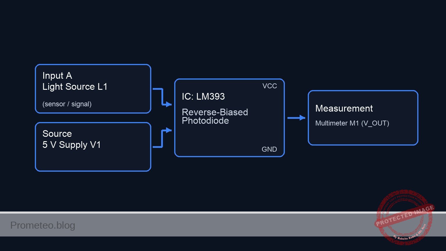
Schematic
[ STIMULUS & POWER ]               [ SENSOR LOGIC ]                     [ OUTPUT ]

    [ Light Source L1 ] ~~~(Light)~~~>+---------------------+
                                      |    Photodiode D1    |
                                      | (Sensor / Rev Bias) |
    [ 5 V Supply V1 ] -----(VCC)------>| Cathode       Anode |----(V_OUT)---> [ Multimeter M1 ]
                                      +----------+----------+      (Volts)
                                                 |
                                           (Photocurrent)
                                                 |
                                                 v
                                      +----------+----------+
                                      |     Resistor R1     |
                                      |      (100 kΩ)       |
                                      +----------+----------+
                                                 |
                                                 v
                                          [ GND (0 V) ]
Measurements and tests
- Dark Test: Cover the photodiode completely with an opaque object or your hand. Measure the voltage at
V_OUT.- Expectation: The reading should be very close to 0 V (typically in the microvolt or low millivolt range), representing the dark current.
- Ambient Light Test: Expose the sensor to normal room lighting.
- Expectation:
V_OUTshould rise significantly (e.g., 0.5 V to 2.0 V, depending on brightness and the exact value of R1).
- Expectation:
- High Intensity Test: Shine a flashlight or bright LED (L1) directly at D1.
- Expectation:
V_OUTshould increase further, potentially approaching the supply voltage limit if the light is very intense.
- Expectation:
- Calculation: Use Ohm’s Law to calculate the photocurrent at any specific light level: Ireverse = VOUT / R1.
SPICE netlist and simulation
Reference SPICE Netlist (ngspice) — excerptFull SPICE netlist (ngspice)
* Practical case: Reverse Bias Photodiode Light Detection

* --- Models ---
* Generic Photodiode Model (Approximation for BPW34)
* Parameters: IS (Sat Current), CJO (Junction Cap), BV (Breakdown), RS (Series Res)
.model BPW34 D(IS=10n RS=5 N=1.1 BV=60 IBV=10u CJO=70p M=0.45 VJ=0.75)

* --- Components ---

* V1: 5 V DC supply
* Wiring: Positive to VCC, Negative to 0 (Ground)
V1 VCC 0 DC 5

* D1: Photodiode (Sensor)
* Wiring Guide: Cathode to VCC, Anode to V_OUT
* Note: SPICE Diode syntax is D
D1 V_OUT VCC BPW34

* L1: External Light Stimulus (White LED/Flashlight)
* Modeled as a Current Source (I_L1) representing the generated photocurrent.
* ... (truncated in public view) ...
Copy this content into a .cir file and run with ngspice.
* Practical case: Reverse Bias Photodiode Light Detection

* --- Models ---
* Generic Photodiode Model (Approximation for BPW34)
* Parameters: IS (Sat Current), CJO (Junction Cap), BV (Breakdown), RS (Series Res)
.model BPW34 D(IS=10n RS=5 N=1.1 BV=60 IBV=10u CJO=70p M=0.45 VJ=0.75)

* --- Components ---

* V1: 5 V DC supply
* Wiring: Positive to VCC, Negative to 0 (Ground)
V1 VCC 0 DC 5

* D1: Photodiode (Sensor)
* Wiring Guide: Cathode to VCC, Anode to V_OUT
* Note: SPICE Diode syntax is D
D1 V_OUT VCC BPW34

* L1: External Light Stimulus (White LED/Flashlight)
* Modeled as a Current Source (I_L1) representing the generated photocurrent.
* In reverse bias, photocurrent flows from Cathode to Anode (internally),
* effectively injecting current from VCC into V_OUT.
* Simulation: Pulsing light from Dark (0A) to Light (30uA).
* Timing: Delay 100us, Rise/Fall 10us, Width 400us, Period 1ms.
I_L1 VCC V_OUT PULSE(0 30u 100u 10u 10u 400u 1m)

* R1: 100 kOhm Load Resistor
* Wiring: One leg to V_OUT, other leg to 0
R1 V_OUT 0 100k

* M1: Multimeter (Voltmeter)
* Function: Measure voltage at V_OUT relative to Ground.
* Implemented via .print output directives below.

* --- Analysis Directives ---

* Transient Analysis:
* Step: 10us, Stop: 3ms (Captures 3 full light pulses)
.tran 10u 3m

* Operating Point Analysis (Initial DC Check):
.op

* Output Printing:
* Prints the voltage at the output node (V_OUT) and supply (VCC)
.print tran V(V_OUT) V(VCC)

.end
Simulation Results (Transient Analysis)

Show raw data table (347 rows)
Index   time            v(v_out)        v(vcc)
0	0.000000e+00	1.000500e-03	5.000000e+00
1	1.000000e-07	1.000500e-03	5.000000e+00
2	2.000000e-07	1.000500e-03	5.000000e+00
3	4.000000e-07	1.000500e-03	5.000000e+00
4	8.000000e-07	1.000500e-03	5.000000e+00
5	1.600000e-06	1.000500e-03	5.000000e+00
6	3.200000e-06	1.000500e-03	5.000000e+00
7	6.400000e-06	1.000500e-03	5.000000e+00
8	1.280000e-05	1.000500e-03	5.000000e+00
9	2.280000e-05	1.000500e-03	5.000000e+00
10	3.280000e-05	1.000500e-03	5.000000e+00
11	4.280000e-05	1.000500e-03	5.000000e+00
12	5.280000e-05	1.000500e-03	5.000000e+00
13	6.280000e-05	1.000500e-03	5.000000e+00
14	7.280000e-05	1.000500e-03	5.000000e+00
15	8.280000e-05	1.000500e-03	5.000000e+00
16	9.280000e-05	1.000500e-03	5.000000e+00
17	1.000000e-04	1.000500e-03	5.000000e+00
18	1.010000e-04	7.978912e-02	5.000000e+00
19	1.030000e-04	3.507154e-01	5.000000e+00
20	1.070000e-04	1.270928e+00	5.000000e+00
21	1.100000e-04	2.076364e+00	5.000000e+00
22	1.108000e-04	2.250021e+00	5.000000e+00
23	1.124000e-04	2.525718e+00	5.000000e+00
... (323 more rows) ...
Common mistakes and how to avoid them
- Forward Biasing the Photodiode: Connecting the Anode to VCC makes the photodiode act like a regular diode (or LED), conducting current constantly regardless of light.
- Solution: Ensure the Cathode (stripe) connects to the positive supply (
VCC).
- Solution: Ensure the Cathode (stripe) connects to the positive supply (
- Resistor Value too Low: Using a 100 Ω or 1 kΩ resistor might result in a voltage output too small for a standard multimeter to read easily.
- Solution: Use a high value resistor (100 kΩ to 1 MΩ) to convert the small microampere photocurrent into a readable voltage.
- Multimeter in Current Mode: Connecting the multimeter in parallel while set to Ammeter mode effectively shorts
V_OUTto ground.- Solution: Always ensure the multimeter is set to DC Volts and connected in parallel with R1.
Troubleshooting
- Symptom: Output voltage is always constant near 5 V (VCC).
- Cause: The photodiode is likely connected in forward bias (Anode to VCC), or the photodiode is shorted.
- Fix: Reverse the photodiode orientation.
- Symptom: Output voltage stays at 0 V even with bright light.
- Cause: Open circuit connections, R1 is shorted, or the photodiode is damaged.
- Fix: Check continuity on the breadboard; verify D1 is actually a photodiode and not a standard LED (which also produces current but much less).
- Symptom: Readings are unstable or «jumpy».
- Cause: Interference from AC powered lights (50/60 Hz flicker) picked up by the high-impedance node
V_OUT. - Fix: Test using a DC light source (flashlight) or add a small capacitor (e.g., 100 nF) in parallel with R1 to filter noise.
- Cause: Interference from AC powered lights (50/60 Hz flicker) picked up by the high-impedance node
Possible improvements and extensions
- Transimpedance Amplifier (TIA): Replace R1 with an Operational Amplifier configured as a TIA. This provides a much faster response time and linear output voltage buffered from the load.
- Light Threshold Alarm: Feed
V_OUTinto a voltage comparator (like an LM393) to trigger a buzzer or LED when the light level exceeds a specific setpoint.
More Practical Cases on Prometeo.blog
        <div class="amazon-affiliate">
          <p><strong>Find this product and/or books on this topic on Amazon</strong></p>
          <p><a class="amazon-affiliate-btn" href="https://amzn.to/4mt8r4C" target="_blank" rel="nofollow sponsored noopener">Go to Amazon</a></p>
          <p class="amazon-affiliate-disclaimer">As an Amazon Associate, I earn from qualifying purchases. If you buy through this link, you help keep this project running.</p>
        </div>
Quick Quiz

Telecommunications Electronics Engineer and Computer Engineer (official degrees in Spain).

