

Level: Medium. Design an emergency stop circuit where a high sensor signal halts a motor using a NOT gate.
Objective and use case
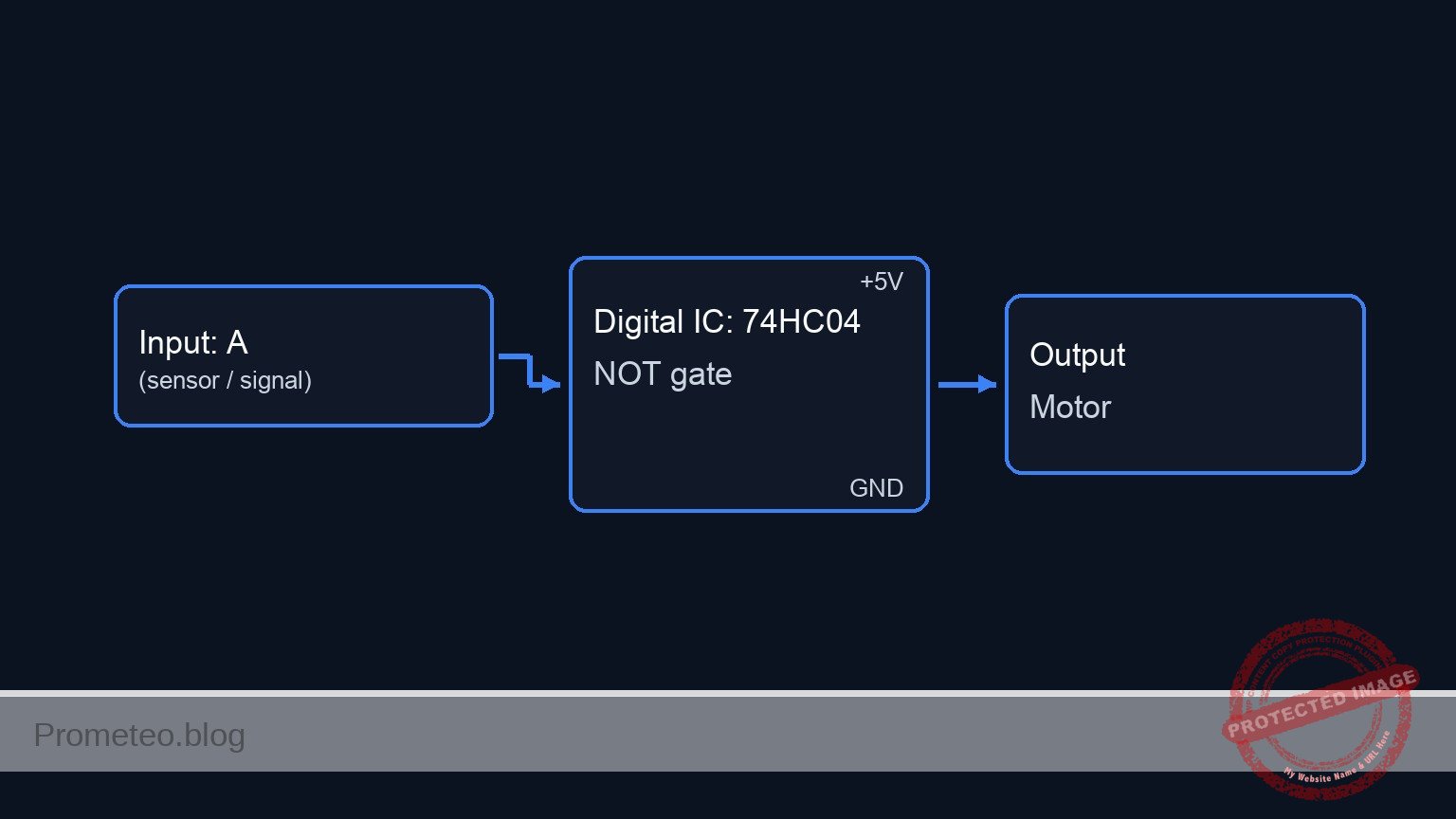
You will design and build a digital safety stop circuit using a 74HC04 inverter. In this configuration, the system defaults to an «ON» state (Motor running) and requires a logic HIGH signal from a sensor to force the system into an «OFF» state.
- Industrial Automation: Used for emergency stop buttons (E-Stop) or limit switches where detecting an object must immediately cut power.
- Fail-Safe Logic: Ensures that active intervention is required to stop the process, while the default idle state of the control logic keeps the machine running (assuming the physical actuator is wired to match).
- Signal Inversion: Adapts sensors with active-high outputs to controllers or drivers requiring active-low disable signals.
Expected Outcome:
* Idle State: Input $0\text{ V}$ (Low) $\rightarrow$ Output $5\text{ V}$ (High) $\rightarrow$ Motor Simulator ON.
* Active State: Input $5\text{ V}$ (High) $\rightarrow$ Output $0\text{ V}$ (Low) $\rightarrow$ Motor Simulator OFF.
* Thresholds: Input voltages above $3.5\text{ V}$ are read as High; below $1.5\text{ V}$ are read as Low.
Target audience: Electronics students and hobbyists familiar with basic digital logic levels.
Materials
- V1: 5 V DC supply, function: Main power source.
- U1: 74HC04 Hex Inverter IC, function: Logic inversion.
- S1: Push-button switch (NO), function: Simulates safety sensor activation.
- R1: 10 kΩ resistor, function: Pull-down for sensor input.
- R2: 330 Ω resistor, function: Current limiting for motor simulator.
- D1: Green LED, function: DC-Motor-Sim (visual indicator of motor power).
- C1: 100 nF capacitor, function: Decoupling for U1 power supply.
Pin-out of the IC used
Chip: 74HC04 (Hex Inverter)
| Pin | Name | Logic function | Connection in this case |
|---|---|---|---|
| 1 | 1A | Input | Connected to Sensor Node (S1, R1) |
| 2 | 1Y | Output | Connected to Motor Control Node (D1 via R2) |
| 7 | GND | Ground | Connected to 0 (GND) |
| 14 | VCC | Power | Connected to VCC (5 V) |
Wiring guide
- V1 connects between node
VCCand node0. - C1 connects between node
VCCand node0(near U1). - S1 connects between node
VCCand nodeSENSOR_IN. - R1 connects between node
SENSOR_INand node0(Pull-down). - U1 Pin 14 connects to
VCC. - U1 Pin 7 connects to
0. - U1 Pin 1 connects to
SENSOR_IN. - U1 Pin 2 connects to
MOTOR_CTRL. - R2 connects between node
MOTOR_CTRLand nodeLED_ANODE. - D1 connects between node
LED_ANODE(Anode) and node0(Cathode).
Conceptual block diagram
Schematic
[ INPUT STAGE ]                     [ LOGIC STAGE ]                     [ OUTPUT STAGE ]

 (VCC)
   |
 [ S1: Button (NO) ] --+
                       |
                       +--(SENSOR_IN)-->+-----------------------+
                       |                |       U1: 74HC04      |
 [ R1: 10k Resistor ] -+                |     (Hex Inverter)    |
   |                                    | Pin 1           Pin 2 | --(MOTOR_CTRL)--> [ R2: 330R ] --> [ D1: Green LED ] --> (GND)
 (GND)                                  |                       |
                                        | Power: [ V1: 5V ]     |
                                        | Filter: [ C1: 100nF ] |
                                        +-----------------------+
Truth table
In this safety logic, $0$ represents $0\text{ V}$ (Ground) and $1$ represents $5\text{ V}$ (VCC).
| Sensor Input (Pin 1) | Motor Command Output (Pin 2) | System State |
|---|---|---|
| 0 (Low) | 1 (High) | RUNNING (Default) |
| 1 (High) | 0 (Low) | STOPPED (Emergency) |
Measurements and tests
-
Idle State Validation:
- Ensure S1 is not pressed.
- Measure voltage at
SENSOR_INrelative to0. Expected: $\approx 0\text{ V}$. - Measure voltage at
MOTOR_CTRL. Expected: $\approx 5\text{ V}$. - Verify D1 (Motor Sim) is lit.
-
Active Stop Validation:
- Press and hold S1.
- Measure voltage at
SENSOR_IN. Expected: $5\text{ V}$. - Measure voltage at
MOTOR_CTRL. Expected: $\approx 0\text{ V}$. - Verify D1 (Motor Sim) turns OFF immediately.
-
Propagation Delay (Optional):
- If using an oscilloscope, connect Channel 1 to
SENSOR_INand Channel 2 toMOTOR_CTRL. - Trigger on the rising edge of Channel 1.
- Measure the time difference between the input reaching 50% and the output falling to 50%. Typical values for 74HC04 are in the nanosecond range ($7\text{–}15\text{ ns}$).
- If using an oscilloscope, connect Channel 1 to
SPICE netlist and simulation
Reference SPICE Netlist (ngspice) — excerptFull SPICE netlist (ngspice)
* Practical case: Safety control with inverse logic

* --- Power Supply ---
* V1 connects between node VCC and node 0
V1 VCC 0 DC 5

* --- Decoupling ---
* C1 connects between node VCC and node 0 (near U1)
C1 VCC 0 100n

* --- Input Stage: Sensor (Push Button) ---
* S1 connects between node VCC and node SENSOR_IN
* Implemented as a Voltage-Controlled Switch to simulate the physical connection
S1 VCC SENSOR_IN S1_CTRL 0 SW_PUSH
.model SW_PUSH SW(Vt=2.5 Ron=0.1 Roff=100Meg)

* Control source for S1 (Simulates user pressing the button)
* Pulse: Press at 200us, hold for 300us, release (Total simulation 1ms)
V_S1_ACT S1_CTRL 0 PULSE(0 5 200u 1u 1u 300u 1ms)

* R1 connects between node SENSOR_IN and node 0 (Pull-down)
R1 SENSOR_IN 0 10k

* --- Logic Stage: U1 (74HC04 Hex Inverter) ---
* U1 Pin 14 connects to VCC
* U1 Pin 7 connects to 0
* U1 Pin 1 connects to SENSOR_IN
* U1 Pin 2 connects to MOTOR_CTRL
* Implemented using a Behavioral Source (B-Source) for robust logic simulation
* Logic: Inverts SENSOR_IN. Uses sigmoid function for convergence.
* ... (truncated in public view) ...
Copy this content into a .cir file and run with ngspice.
* Practical case: Safety control with inverse logic

* --- Power Supply ---
* V1 connects between node VCC and node 0
V1 VCC 0 DC 5

* --- Decoupling ---
* C1 connects between node VCC and node 0 (near U1)
C1 VCC 0 100n

* --- Input Stage: Sensor (Push Button) ---
* S1 connects between node VCC and node SENSOR_IN
* Implemented as a Voltage-Controlled Switch to simulate the physical connection
S1 VCC SENSOR_IN S1_CTRL 0 SW_PUSH
.model SW_PUSH SW(Vt=2.5 Ron=0.1 Roff=100Meg)

* Control source for S1 (Simulates user pressing the button)
* Pulse: Press at 200us, hold for 300us, release (Total simulation 1ms)
V_S1_ACT S1_CTRL 0 PULSE(0 5 200u 1u 1u 300u 1ms)

* R1 connects between node SENSOR_IN and node 0 (Pull-down)
R1 SENSOR_IN 0 10k

* --- Logic Stage: U1 (74HC04 Hex Inverter) ---
* U1 Pin 14 connects to VCC
* U1 Pin 7 connects to 0
* U1 Pin 1 connects to SENSOR_IN
* U1 Pin 2 connects to MOTOR_CTRL
* Implemented using a Behavioral Source (B-Source) for robust logic simulation
* Logic: Inverts SENSOR_IN. Uses sigmoid function for convergence.
* Vout = VCC if Vin < 2.5V, else 0V.
B_U1 MOTOR_CTRL 0 V = V(VCC) * (1 / (1 + exp(50 * (V(SENSOR_IN) - 2.5))))

* --- Output Stage: Motor Simulator (LED) ---
* R2 connects between node MOTOR_CTRL and node LED_ANODE
R2 MOTOR_CTRL LED_ANODE 330

* D1 connects between node LED_ANODE (Anode) and node 0 (Cathode)
D1 LED_ANODE 0 LED_GREEN
.model LED_GREEN D(IS=1e-22 RS=5 N=1.5 BV=5 IBV=10u CJO=10p)

* --- Simulation Directives ---
* Perform a transient analysis to observe the button press event
.op
.tran 1u 1ms

* Print required nodes for verification
.print tran V(SENSOR_IN) V(MOTOR_CTRL) V(LED_ANODE)

.end
Simulation Results (Transient Analysis)

Show raw data table (1061 rows)
Index   time            v(sensor_in)    v(motor_ctrl)   v(led_anode)
0	0.000000e+00	4.999500e-04	5.000000e+00	1.833072e+00
1	1.000000e-08	4.999500e-04	5.000000e+00	1.833072e+00
2	2.000000e-08	4.999500e-04	5.000000e+00	1.833072e+00
3	4.000000e-08	4.999500e-04	5.000000e+00	1.833072e+00
4	8.000000e-08	4.999500e-04	5.000000e+00	1.833072e+00
5	1.600000e-07	4.999500e-04	5.000000e+00	1.833072e+00
6	3.200000e-07	4.999500e-04	5.000000e+00	1.833072e+00
7	6.400000e-07	4.999500e-04	5.000000e+00	1.833072e+00
8	1.280000e-06	4.999500e-04	5.000000e+00	1.833072e+00
9	2.280000e-06	4.999500e-04	5.000000e+00	1.833072e+00
10	3.280000e-06	4.999500e-04	5.000000e+00	1.833072e+00
11	4.280000e-06	4.999500e-04	5.000000e+00	1.833072e+00
12	5.280000e-06	4.999500e-04	5.000000e+00	1.833072e+00
13	6.280000e-06	4.999500e-04	5.000000e+00	1.833072e+00
14	7.280000e-06	4.999500e-04	5.000000e+00	1.833072e+00
15	8.280000e-06	4.999500e-04	5.000000e+00	1.833072e+00
16	9.280000e-06	4.999500e-04	5.000000e+00	1.833072e+00
17	1.028000e-05	4.999500e-04	5.000000e+00	1.833072e+00
18	1.128000e-05	4.999500e-04	5.000000e+00	1.833072e+00
19	1.228000e-05	4.999500e-04	5.000000e+00	1.833072e+00
20	1.328000e-05	4.999500e-04	5.000000e+00	1.833072e+00
21	1.428000e-05	4.999500e-04	5.000000e+00	1.833072e+00
22	1.528000e-05	4.999500e-04	5.000000e+00	1.833072e+00
23	1.628000e-05	4.999500e-04	5.000000e+00	1.833072e+00
... (1037 more rows) ...
Common mistakes and how to avoid them
- Floating Input: Omitting R1 (Pull-down) causes the input to float, making the motor toggle randomly or oscillate based on electromagnetic noise. Fix: Always ensure inputs have a defined path to ground or VCC when the switch is open.
- Overloading the Output: Connecting a real DC motor directly to the 74HC04 output. The chip can only source $\approx 20\text{ mA}$. Fix: Use the output to drive a transistor (BJT or MOSFET) which then switches the actual motor.
- Confusing Logic Families: Using a 74LS04 with high-value resistors or incorrect voltage levels. Fix: Stick to the 74HC series for 5 V CMOS compatibility and high impedance inputs.
Troubleshooting
- Symptom: The Motor (LED) is always OFF.
- Cause: Input pin stuck HIGH or damaged IC.
- Fix: Check voltage at Pin 1. If 0 V, replace U1.
- Symptom: The Motor (LED) is always ON, even when button is pressed.
- Cause: Input shorted to GND or button S1 not making contact.
- Fix: Use a multimeter to verify continuity across S1 when pressed.
- Symptom: LED flickers when touching the wire.
- Cause: Missing pull-down resistor R1.
- Fix: Verify R1 is connected securely between Pin 1 and Ground.
Possible improvements and extensions
- Latching Safety Circuit: Add a feedback loop or an SR Latch so that once the emergency stop is triggered, the motor remains off even if the button is released (requires a manual reset).
- Status Indicators: Add a Red LED connected to the input side (buffered) to indicate «EMERGENCY STATE» visually alongside the motor shutdown.
More Practical Cases on Prometeo.blog
Find this product and/or books on this topic on Amazon
As an Amazon Associate, I earn from qualifying purchases. If you buy through this link, you help keep this project running.
Quick Quiz

Telecommunications Electronics Engineer and Computer Engineer (official degrees in Spain).

