
Level: Basic – Build a circuit where an LED dims as ambient light increases.
Objective and use case
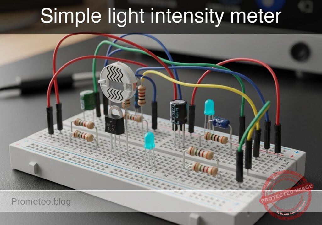
You will construct a simple analog light sensor circuit using a photoresistor (LDR) in a configuration where the light output is inversely proportional to the ambient light intensity. This creates a «Dark Sensor» effect without using transistors.
Why it is useful:
* Automatic Lighting: Simulates street lamps or night lights that turn on automatically when it gets dark.
* Battery Efficiency: Ensures indicators are only active during low-light conditions when visibility is poor.
* Security Systems: Can detect if a sealed container or dark room has been breached by light.
* Concept Demonstration: Demonstrates current division and non-linear resistance components in parallel circuits.
Expected outcome:
* Dark condition: The LDR resistance is high, forcing current through the LED. The Red LED turns ON.
* Bright condition: The LDR resistance drops significantly, shunting current away from the LED. The Red LED turns OFF or dims significantly.
* Voltage shift: You will measure a voltage drop at the shared node as light increases.
* Target audience: Beginners and students familiar with basic breadboarding.
Materials
- V1: 5 V DC supply, function: main power source
- R1: 470 Ω resistor, function: current limiting and voltage divider upper leg
- R2: LDR (GL5528 or similar), function: ambient light sensor (variable resistor)
- D1: Red LED, function: low-light indicator
Wiring guide
We will use a «current shunt» topology. The LDR is placed in parallel with the LED.
- VCC: Connect positive terminal of V1 to one side of R1.
- VA: Connect the other side of R1 to the Anode (long leg) of D1.
- VA: Connect one leg of R2 (LDR) to the same node (Anode of D1).
- 0 (GND): Connect the Cathode (flat side/short leg) of D1 to the negative terminal of V1.
- 0 (GND): Connect the remaining leg of R2 (LDR) to the negative terminal of V1.
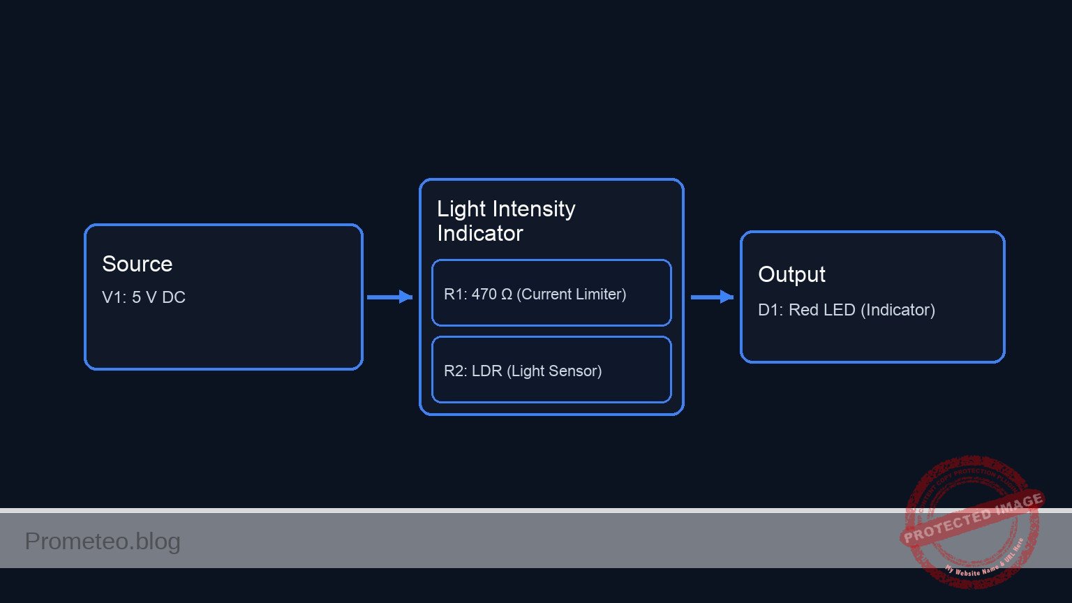
Conceptual block diagram
Schematic
[ POWER SOURCE ]              [ CURRENT LIMITER ]               [ SHUNT TOPOLOGY ]

                                                              +--> [ D1: Red LED ] --> GND
                                                              |    (Output Indicator)
    [ V1: 5 V DC ] --(+)--> [ R1: 470 Ω ] --(Node VA)--> [ + ]
                                                              |
                                                              +--> [ R2: LDR ] --> GND
                                                                   (Light Sensor)
Measurements and tests
To validate that the circuit behaves inversely to light intensity:
- Set up the multimeter: Select DC Voltage mode (20 V range).
- Connect probes: Place the Red probe on node VA (Anode of LED) and Black probe on 0 (GND).
- Test 1 (Ambient/Bright Light):
- Expose the LDR to bright light.
- Observation: The LED should be DIM or OFF.
- Measurement: The voltage at VA should drop below the LED forward voltage (likely < 1.5 V). The low resistance of the LDR shunts the current to ground.
- Test 2 (Darkness):
- Cover the LDR completely with your finger or a cap.
- Observation: The LED should light up BRIGHTLY.
- Measurement: The voltage at VA should rise to the LED’s forward voltage (approx. 1.8 V to 2.0 V for a red LED). The high resistance of the LDR forces current through the LED.
SPICE netlist and simulation
Reference SPICE Netlist (ngspice) — excerptFull SPICE netlist (ngspice)
* Practical case: Simple light intensity meter

* --- Models ---
* Generic Red LED Model
* Parameters: IS=saturation current, N=emission coefficient, RS=series resistance
* BV=breakdown voltage, IBV=breakdown current, CJO=junction capacitance
.model DLED D(IS=1e-14 N=2 RS=10 BV=5 IBV=10u CJO=20p)

* --- Power Supply ---
* V1: 5V DC supply (Main power source)
* Connected between VCC and GND (0)
V1 VCC 0 DC 5

* --- Circuit Components ---
* R1: 470 Ohm resistor
* Function: Current limiting and voltage divider upper leg
* Wiring: Connects Positive Terminal of V1 (VCC) to Node VA
R1 VCC VA 470

* D1: Red LED
* ... (truncated in public view) ...
Copy this content into a .cir file and run with ngspice.
* Practical case: Simple light intensity meter

* --- Models ---
* Generic Red LED Model
* Parameters: IS=saturation current, N=emission coefficient, RS=series resistance
* BV=breakdown voltage, IBV=breakdown current, CJO=junction capacitance
.model DLED D(IS=1e-14 N=2 RS=10 BV=5 IBV=10u CJO=20p)

* --- Power Supply ---
* V1: 5V DC supply (Main power source)
* Connected between VCC and GND (0)
V1 VCC 0 DC 5

* --- Circuit Components ---
* R1: 470 Ohm resistor
* Function: Current limiting and voltage divider upper leg
* Wiring: Connects Positive Terminal of V1 (VCC) to Node VA
R1 VCC VA 470

* D1: Red LED
* Function: Low-light indicator
* Wiring: Anode to Node VA, Cathode to Negative Terminal of V1 (0)
D1 VA 0 DLED

* R2: LDR (GL5528 or similar)
* Function: Ambient light sensor (variable resistor)
* Wiring: Connects Node VA to Negative Terminal of V1 (0)
* Note: Modeled as a behavioral resistor where Resistance = V(V_LDR_CTRL).
* This allows simulating the change from Light (Low R) to Dark (High R).
R2 VA 0 R='V(V_LDR_CTRL)'

* --- Dynamic Stimuli (Simulation Only) ---
* V_LDR_SRC: Generates a voltage signal representing the LDR resistance in Ohms.
* Logic:
*   - 100V (representing 100 Ohms) = Bright Light -> V(VA) drops -> LED OFF
*   - 10kV (representing 10k Ohms) = Dark -> V(VA) rises -> LED ON
* Timing: Fast pulse to demonstrate switching.
* PULSE(v1 v2 td tr tf pw per)
V_LDR_SRC V_LDR_CTRL 0 PULSE(100 10000 10u 100u 100u 500u 1000u)

* --- Analysis Directives ---
* Transient analysis: 5us step size, 2ms duration
.tran 5u 2ms

* Print specific nodes to verify operation
* V(VA): Voltage at the LED/LDR node (Should swing between ~0.8V and ~1.8V)
* V(V_LDR_CTRL): The resistance value being simulated
.print tran V(VA) V(V_LDR_CTRL)

.op
.end
Simulation Results (Transient Analysis)

Show raw data table (441 rows)
Index   time            v(va)           v(v_ldr_ctrl)
0	0.000000e+00	8.771739e-01	1.000000e+02
1	5.000000e-08	8.771739e-01	1.000000e+02
2	1.000000e-07	8.771739e-01	1.000000e+02
3	2.000000e-07	8.771739e-01	1.000000e+02
4	4.000000e-07	8.771739e-01	1.000000e+02
5	8.000000e-07	8.771739e-01	1.000000e+02
6	1.600000e-06	8.771739e-01	1.000000e+02
7	3.200000e-06	8.771739e-01	1.000000e+02
8	6.400000e-06	8.771739e-01	1.000000e+02
9	1.000000e-05	8.771739e-01	1.000000e+02
10	1.016024e-05	9.861073e-01	1.158634e+02
11	1.048071e-05	1.182699e+00	1.475902e+02
12	1.112165e-05	1.342799e+00	2.110437e+02
13	1.175485e-05	1.386540e+00	2.737299e+02
14	1.276008e-05	1.418826e+00	3.732481e+02
15	1.399489e-05	1.436968e+00	4.954940e+02
16	1.646450e-05	1.455127e+00	7.399857e+02
17	2.140373e-05	1.468889e+00	1.228969e+03
18	2.640373e-05	1.474732e+00	1.723969e+03
19	3.140373e-05	1.478748e+00	2.218969e+03
20	3.640373e-05	1.480441e+00	2.713969e+03
21	4.140373e-05	1.481529e+00	3.208969e+03
22	4.640373e-05	1.482571e+00	3.703969e+03
23	5.140373e-05	1.483189e+00	4.198969e+03
... (417 more rows) ...
Common mistakes and how to avoid them
- Placing components in Series:
- Mistake: Wiring Source -> Resistor -> LDR -> LED -> Ground.
- Result: This creates a «Light Sensor» (brighter light = brighter LED), which is the opposite of the objective.
- Solution: Ensure the LDR is in parallel with the LED (sharing the same start and end nodes).
- Using a resistor value that is too high for R1:
- Mistake: Using a 10 kΩ resistor for R1.
- Result: The LED never turns on brightly even in total darkness because the current is too restricted.
- Solution: Use 330 Ω to 470 Ω for a 5 V source to ensure sufficient current for the LED when the LDR is high-resistance.
- Expecting a «Hard» On/Off switch:
- Mistake: Expecting digital-like switching.
- Result: The LED dims gradually rather than snapping off.
- Solution: Understand that this is a passive analog circuit. For a hard «snap» action, a transistor or comparator would be required.
Troubleshooting
- Symptom: LED is always ON, even in bright light.
- Cause: R1 value is too low, or LDR has very high resistance even in light (or is disconnected).
- Fix: Check LDR connections. If correct, increase R1 to 1 kΩ to make it easier for the LDR to pull the voltage down.
- Symptom: LED is always OFF.
- Cause: LED wired backwards or R1 is too high.
- Fix: Flip the LED orientation. Ensure R1 is < 1 kΩ.
- Symptom: Source gets hot.
- Cause: Short circuit. Likely R1 was bypassed, connecting VCC directly to the LDR or LED.
- Fix: Ensure R1 is strictly between VCC and the VA node.
Possible improvements and extensions
- Sensitivity Adjustment: Replace R1 with a 1 kΩ potentiometer to tune exactly how dark it needs to be before the LED turns on.
- Color Mixing: Put a Green LED in series with the LDR (instead of parallel). As light increases, the Green LED gets brighter while the Red LED (parallel) gets dimmer, creating a color-shifting light monitor.
More Practical Cases on Prometeo.blog
Find this product and/or books on this topic on Amazon
As an Amazon Associate, I earn from qualifying purchases. If you buy through this link, you help keep this project running.
Quick Quiz

Telecommunications Electronics Engineer and Computer Engineer (official degrees in Spain).

