Level: Medium. Design a control circuit that compares light levels from two sensors to orient a motor towards the brightest light source.
Objective and use case
This practical case guides you through building an analog control loop that automatically orients a mechanism towards a light source using photoresistors (LDRs) and operational amplifiers. You will construct a «sun seeker» that actively balances two light inputs to drive a motor in the corresponding direction.
- Real-world applications:
- Solar Energy: Increases photovoltaic panel efficiency by keeping panels perpendicular to the sun throughout the day.
- Robotics: Enables light-seeking behaviors (phototaxis) in autonomous robots.
- Home Automation: Controls smart blinds to regulate room temperature based on sunlight intensity.
- Expected outcome:
- When the light source is balanced, the motor remains stationary.
- When LDR1 is shaded, the voltage difference triggers the motor to spin Clockwise (CW).
- When LDR2 is shaded, the motor spins Counter-Clockwise (CCW).
- Target audience: Electronics students familiar with voltage dividers and OpAmps.
Materials
- V1: 9 V DC power supply (Power source).
- R1: Photoresistor (LDR), function: Left light sensor.
- R2: Photoresistor (LDR), function: Right light sensor.
- R3: 10 kΩ resistor, function: Voltage divider bottom leg for R1.
- R4: 10 kΩ resistor, function: Voltage divider bottom leg for R2.
- U1: LM358, function: Dual Operational Amplifier (Comparators).
- U2: L293D, function: H-Bridge Motor Driver IC.
- M1: 9 V DC Gear Motor, function: Tracking actuator.
- C1: 100 nF capacitor, function: Power supply decoupling.
Wiring guide
This circuit uses two parallel voltage dividers compared by two OpAmps to determine motor direction.
- Power Supply:
- Connect
V1positive terminal to nodeVCC. - Connect
V1negative terminal to nodeGND(0). -
Connect
C1betweenVCCandGND. -
Sensors (Dual Voltage Divider):
- Connect
R1(LDR Left) betweenVCCand nodeVA(Sensor Voltage A). - Connect
R3betweenVAandGND. - Connect
R2(LDR Right) betweenVCCand nodeVB(Sensor Voltage B). -
Connect
R4betweenVBandGND. -
Comparators (LM358 – U1):
- Comparator A (Turn Right/CW Logic):
- Connect
U1Non-inverting input (+) to nodeVA. - Connect
U1Inverting input (-) to nodeVB. - Connect
U1Output A to nodeSIG_CW.
- Connect
- Comparator B (Turn Left/CCW Logic):
- Connect
U1Non-inverting input (+) to nodeVB. - Connect
U1Inverting input (-) to nodeVA. - Connect
U1Output B to nodeSIG_CCW.
- Connect
-
Connect
U1VCC pin toVCCand GND pin toGND. -
Motor Driver (L293D – U2):
- Connect
U2Input 1 to nodeSIG_CW. - Connect
U2Input 2 to nodeSIG_CCW. - Connect
U2Enable 1 pin toVCC. - Connect
U2Output 1 to nodeM_POS. - Connect
U2Output 2 to nodeM_NEG. - Connect
U2VCC1 (Logic) and VCC2 (Power) toVCC. -
Connect
U2GND pins toGND. -
Actuator:
- Connect
M1(Motor) between nodesM_POSandM_NEG.
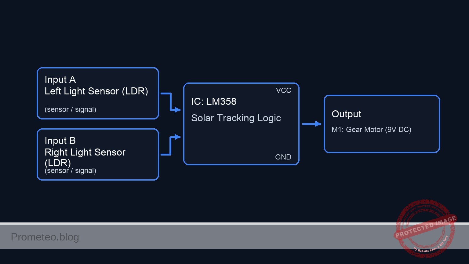
Conceptual block diagram
Schematic
[ INPUTS / SENSORS ]               [ LOGIC / PROCESSING ]                  [ ACTUATOR ]

   [ Power Supply Block ]
   [ Source: V1 (9 V)    ] --(VCC/GND Power)--> (Distributes to all ICs and Sensors)
   [ Filter: C1 (100nF) ]

                                         [ U1: LM358 Dual OpAmp ]
                                         |                      |
   [ Left Light Sensor  ]                | Comparator A (Logic) |
   [ Top: R1 (LDR)      ] --(Signal VA)->| Input: VA > VB ?     |--(SIG_CW)--->+
   [ Bot: R3 (10k Ohm)  ]                | Output: Turn CW      |              |
                                         |                      |              |
                                         |                      |              v
                                         | Comparator B (Logic) |      [ U2: L293D H-Bridge ]
   [ Right Light Sensor ]                | Input: VB > VA ?     |      |                    |
   [ Top: R2 (LDR)      ] --(Signal VB)->| Output: Turn CCW     |      | Input 1: CW Sig    |
   [ Bot: R4 (10k Ohm)  ]                |                      |      | Input 2: CCW Sig   |===(High Current)==> [ M1: Gear Motor ]
                                         +----------+-----------+      | Enable: VCC        |      (9 V DC)
                                                    |                  | VCC1/VCC2: 9 V      |
                                                    +--(SIG_CCW)------>| GND: Common        |
                                                                       +--------------------+
Measurements and tests
Follow these steps to validate the tracker logic:
-
Static Equilibrium Test:
- Expose both LDRs to ambient light equally.
- Measure the voltage at node
VAandVB. They should be approximately equal. - Measure
SIG_CWandSIG_CCW. Both should be Low (approx. 0 V) or balanced, keeping the motor stopped.
-
Left Shade Simulation:
- Cover
R1(Left LDR) with your hand. - Observation: The resistance of
R1increases, causing voltage atVAto drop. - Logic Check: Since
VB>VA, Comparator B (Non-inverting =VB) should go High (SIG_CCW≈ VCC). - Actuator: The motor should spin Counter-Clockwise.
- Cover
-
Right Shade Simulation:
- Expose
R1to light and coverR2(Right LDR). - Observation: The resistance of
R2increases, causing voltage atVBto drop. - Logic Check: Since
VA>VB, Comparator A (Non-inverting =VA) should go High (SIG_CW≈ VCC). - Actuator: The motor should spin Clockwise.
- Expose
SPICE netlist and simulation
Reference SPICE Netlist (ngspice) — excerptFull SPICE netlist (ngspice)
* Single-axis Solar Tracker Simulation
* Based on Practical Electronics Breadboard Case

* --- Power Supply ---
* V1: 9 V DC power supply
V1 VCC 0 DC 9V
* C1: 100 nF capacitor (Decoupling)
C1 VCC 0 100nF

* --- Dynamic Light Stimulus (Virtual Control) ---
* This source simulates the position of the sun moving from Left to Right.
* 0V = Light on Left Sensor, 5V = Light on Right Sensor.
* Sweeps linearly from 0V to 5V over 100ms.
V_LIGHT LIGHT_POS 0 PWL(0 0 100m 5)

* --- Sensors (LDRs) ---
* Modeled as voltage-dependent resistors controlled by LIGHT_POS.
* R1 (Left LDR): Resistance increases as Light moves Right (LIGHT_POS increases).
* Range: 1k (Bright) to 50k (Dark).
R1 VCC VA R = '1k + 49k * (V(LIGHT_POS)/5)'
* ... (truncated in public view) ...
Copy this content into a .cir file and run with ngspice.
* Single-axis Solar Tracker Simulation
* Based on Practical Electronics Breadboard Case

* --- Power Supply ---
* V1: 9 V DC power supply
V1 VCC 0 DC 9V
* C1: 100 nF capacitor (Decoupling)
C1 VCC 0 100nF

* --- Dynamic Light Stimulus (Virtual Control) ---
* This source simulates the position of the sun moving from Left to Right.
* 0V = Light on Left Sensor, 5V = Light on Right Sensor.
* Sweeps linearly from 0V to 5V over 100ms.
V_LIGHT LIGHT_POS 0 PWL(0 0 100m 5)

* --- Sensors (LDRs) ---
* Modeled as voltage-dependent resistors controlled by LIGHT_POS.
* R1 (Left LDR): Resistance increases as Light moves Right (LIGHT_POS increases).
* Range: 1k (Bright) to 50k (Dark).
R1 VCC VA R = '1k + 49k * (V(LIGHT_POS)/5)'

* R2 (Right LDR): Resistance decreases as Light moves Right.
* Range: 50k (Dark) to 1k (Bright).
R2 VCC VB R = '1k + 49k * (1 - V(LIGHT_POS)/5)'

* --- Voltage Divider Bottom Legs ---
* R3: 10 kΩ resistor for R1
R3 VA 0 10k
* R4: 10 kΩ resistor for R2
R4 VB 0 10k

* --- Comparators (U1: LM358) ---
* U1 is a Dual OpAmp. We define a subcircuit matching the 8-pin DIP pinout.
* Pinout: 1=OutA, 2=In-A, 3=In+A, 4=GND, 5=In+B, 6=In-B, 7=OutB, 8=VCC
* Wiring Guide:
* Comparator A (CW): (+) VA, (-) VB -> Out SIG_CW
* Comparator B (CCW): (+) VB, (-) VA -> Out SIG_CCW
XU1 SIG_CW VB VA 0 VB VA SIG_CCW VCC LM358_DIP8

* --- Motor Driver (U2: L293D) ---
* U2 is an H-Bridge Driver. We define a subcircuit for the used pins.
* Pinout used: 1=EN1, 2=IN1, 3=OUT1, 4/5=GND, 6=OUT2, 7=IN2, 8=VCC2, 16=VCC1
* Wiring Guide:
* IN1=SIG_CW, IN2=SIG_CCW, OUT1=M_POS, OUT2=M_NEG, EN1=VCC
XU2 VCC SIG_CW M_POS 0 0 M_NEG SIG_CCW VCC VCC L293D_BRIDGE

* --- Actuator (M1: 9V DC Gear Motor) ---
* Modeled as a resistive/inductive load.
R_M1 M_POS M_INT 20
L_M1 M_INT M_NEG 5mH

* --- Subcircuit Definitions ---

.subckt LM358_DIP8 OUTA INMA INPA GND INPB INMB OUTB VCC
* Comparator A Behavior (Sigmoid for convergence)
* Output swings approx 0V to VCC-1.5V
B_OUTA OUTA 0 V = (V(VCC)-1.5) / (1 + exp(-50*(V(INPA)-V(INMA)))) + 0.05
* Comparator B Behavior
B_OUTB OUTB 0 V = (V(VCC)-1.5) / (1 + exp(-50*(V(INPB)-V(INMB)))) + 0.05
.ends

.subckt L293D_BRIDGE EN1 IN1 OUT1 GND1 GND2 OUT2 IN2 VCC2 VCC1
* Logic Threshold approx 2.0V.
* Output Voltage ~ VCC2 - 1.4V drop.
* Enable Logic
B_EN node_en 0 V = 1 / (1 + exp(-50*(V(EN1)-2.0)))
* Output 1 (M_POS)
B_O1 OUT1 0 V = V(node_en) * (1/(1+exp(-50*(V(IN1)-2.0)))) * (V(VCC2)-1.4)
* Output 2 (M_NEG)
B_O2 OUT2 0 V = V(node_en) * (1/(1+exp(-50*(V(IN2)-2.0)))) * (V(VCC2)-1.4)
.ends

* --- Simulation Directives ---
.op
* Transient analysis: 100ms duration to capture the full light sweep
.tran 100u 100m

* Print signals to verify logic:
* VA/VB: Sensor Voltages
* SIG_CW/CCW: Comparator Logic Outputs
* M_POS/M_NEG: Motor Drive Voltages
.print tran V(VA) V(VB) V(SIG_CW) V(SIG_CCW) V(M_POS) V(M_NEG) V(LIGHT_POS)

.end
Simulation Results (Transient Analysis)

Show raw data table (3024 rows)
Index   time            v(va)           v(vb)           v(sig_cw)
0	0.000000e+00	8.181818e+00	1.500000e+00	7.550000e+00
1	1.000000e-06	8.181454e+00	1.500012e+00	7.550000e+00
2	2.000000e-06	8.181089e+00	1.500025e+00	7.550000e+00
3	4.000000e-06	8.180361e+00	1.500049e+00	7.550000e+00
4	8.000000e-06	8.178903e+00	1.500098e+00	7.550000e+00
5	1.600000e-05	8.175990e+00	1.500196e+00	7.550000e+00
6	3.200000e-05	8.170168e+00	1.500392e+00	7.550000e+00
7	6.400000e-05	8.158542e+00	1.500784e+00	7.550000e+00
8	1.280000e-04	8.135365e+00	1.501569e+00	7.550000e+00
9	2.280000e-04	8.099394e+00	1.502797e+00	7.550000e+00
10	3.280000e-04	8.063833e+00	1.504028e+00	7.550000e+00
11	4.280000e-04	8.028586e+00	1.505260e+00	7.550000e+00
12	5.280000e-04	7.993645e+00	1.506495e+00	7.550000e+00
13	6.280000e-04	7.959008e+00	1.507732e+00	7.550000e+00
14	7.280000e-04	7.924669e+00	1.508970e+00	7.550000e+00
15	8.280000e-04	7.890626e+00	1.510211e+00	7.550000e+00
16	9.280000e-04	7.856873e+00	1.511454e+00	7.550000e+00
17	1.028000e-03	7.823409e+00	1.512699e+00	7.550000e+00
18	1.128000e-03	7.790228e+00	1.513945e+00	7.550000e+00
19	1.228000e-03	7.757327e+00	1.515194e+00	7.550000e+00
20	1.328000e-03	7.724703e+00	1.516445e+00	7.550000e+00
21	1.428000e-03	7.692352e+00	1.517698e+00	7.550000e+00
22	1.528000e-03	7.660271e+00	1.518953e+00	7.550000e+00
23	1.628000e-03	7.628457e+00	1.520211e+00	7.550000e+00
... (3000 more rows) ...
Common mistakes and how to avoid them
-
LDRs placed too close together:
- Symptom: The system is insensitive and requires extreme light angles to react.
- Solution: Mount the LDRs with a physical blinder (a piece of cardboard or plastic) between them so a shadow is cast on one LDR when the light is not perfectly centered.
-
Driving the motor directly from OpAmps:
- Symptom: The motor hums but doesn’t turn, or the OpAmp overheats and fails.
- Solution: Always use a current driver stage like the L293D or a transistor H-Bridge. OpAmps cannot supply the current required by motors (typically >100 mA).
-
Lack of Deadband (Jittering):
- Symptom: The motor constantly vibrates back and forth when the light is centered.
- Solution: This basic topology is a «bang-bang» controller. In advanced designs, add hysteresis resistors to the OpAmps to create a small voltage window where the motor remains off.
Troubleshooting
- Motor spins in the wrong direction:
- Cause: The motor polarity is reversed relative to the sensor placement.
- Fix: Swap the connections of
M1(M_POS and M_NEG) OR physically swap the positions ofR1andR2.
- Motor runs continuously even in equal light:
- Cause: Large tolerance difference between the two LDRs or fixed resistors (R3/R4).
- Fix: Replace one fixed resistor (e.g., R3) with a 10k trim potentiometer to calibrate the bridge balance manually.
- Nothing happens when light changes:
- Cause: L293D Enable pin not connected high.
- Fix: Ensure the Enable pin of the driver is connected to VCC.
Possible improvements and extensions
- Sensitivity Control: Replace the fixed resistors R3 and R4 with a single multi-turn potentiometer. Connect the wiper to ground and the ends to the LDRs to allow fine-tuning of the center point.
- Solar Power Integration: Replace V1 with a small solar panel and a charging circuit to make the tracker self-sustaining.
More Practical Cases on Prometeo.blog
Find this product and/or books on this topic on Amazon
As an Amazon Associate, I earn from qualifying purchases. If you buy through this link, you help keep this project running.
Quick Quiz

Telecommunications Electronics Engineer and Computer Engineer (official degrees in Spain).