

Level: Basic. Implement a logic safety stop for a water pump using a NAND gate.
Objective and use case
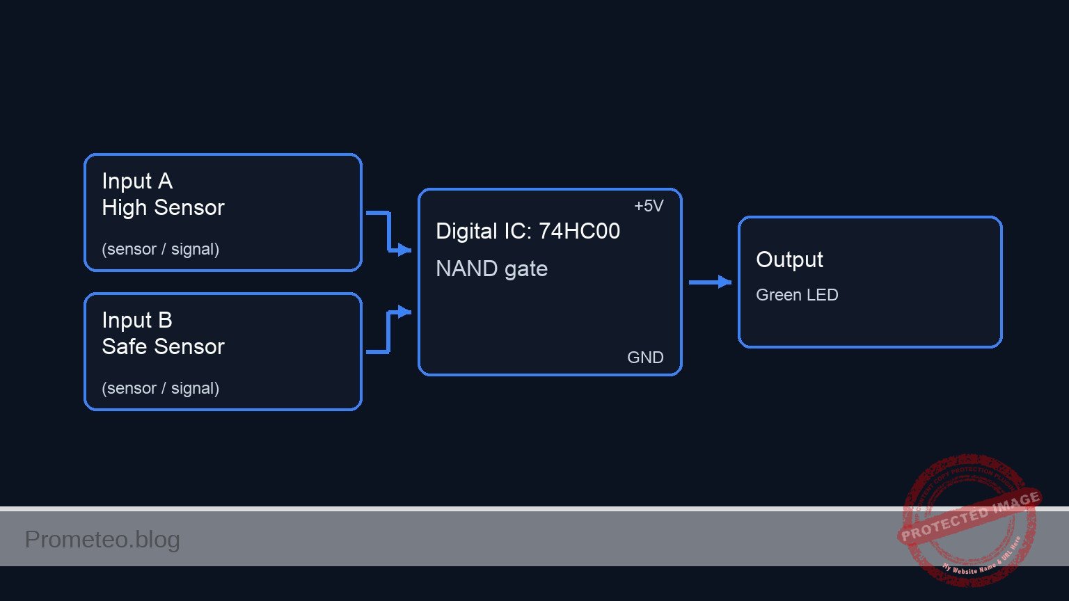
In this session, you will build a digital safety circuit using a 74HC00 NAND gate. The circuit monitors two liquid level sensors and automatically cuts power to a «pump» (simulated by an LED) only when both sensors indicate the tank is dangerously full.
- Industrial tank filling: Prevents chemical spills by ensuring redundant sensors must agree before triggering an emergency shutdown.
- Sump pump systems: Prevents motor burnout or overflow by managing logic states between high-water and critical-overflow marks.
- Home automation: Simple logic for reservoir management without needing a microcontroller.
Expected outcome:
* Normal Operation: The LED (pump) remains ON (Logic High, ~5 V) when the tank is empty or partially full.
* Emergency Stop: The LED turns OFF (Logic Low, ~0 V) immediately when both switch inputs are Logic High (simulating water detection).
* Validation: A specific Truth Table will be verified where only the input condition 1, 1 results in an output of 0.
Target audience: Basic level electronics students and hobbyists.
Materials
- V1: 5 V DC power supply, function: Main circuit power.
- U1: 74HC00, function: Quad 2-Input NAND Gate IC.
- S1: SPST Toggle Switch, function: High Level Sensor simulator.
- S2: SPST Toggle Switch, function: Safety Level Sensor simulator.
- R1: 10 kΩ resistor, function: Pull-down for S1.
- R2: 10 kΩ resistor, function: Pull-down for S2.
- R3: 330 Ω resistor, function: Current limiting for the Pump Status LED.
- D1: Green LED, function: Pump status indicator (ON = Running, OFF = Stopped).
Pin-out of the IC used
Chip: 74HC00 (Quad 2-Input NAND Gate)
| Pin | Name | Logic function | Connection in this case |
|---|---|---|---|
| 1 | 1 A | Input A | Connected to Sensor S1 |
| 2 | 1B | Input B | Connected to Sensor S2 |
| 3 | 1Y | Output Y | Connected to LED (Pump) |
| 7 | GND | Ground | Connected to 0 V |
| 14 | VCC | Power | Connected to 5 V |
Wiring guide
Construct the circuit following these node connections. Ensure the power supply is off while building.
- Power Rail: Connect V1 positive terminal to node
VCCand negative terminal to node0(GND). - IC Power: Connect U1 pin 14 to
VCCand pin 7 to0. - Sensor 1 (Input A):
- Connect S1 between
VCCand nodeSENSOR_HI. - Connect R1 between
SENSOR_HIand0(Pull-down). - Connect U1 pin 1 to node
SENSOR_HI.
- Connect S1 between
- Sensor 2 (Input B):
- Connect S2 between
VCCand nodeSENSOR_SAFE. - Connect R2 between
SENSOR_SAFEand0(Pull-down). - Connect U1 pin 2 to node
SENSOR_SAFE.
- Connect S2 between
- Pump Control (Output):
- Connect U1 pin 3 to node
PUMP_CTRL. - Connect D1 (Anode) to node
PUMP_CTRL. - Connect D1 (Cathode) to node
LED_NODE. - Connect R3 between
LED_NODEand0.
- Connect U1 pin 3 to node
Conceptual block diagram
Schematic
Title: Practical case: Water tank level control

      INPUTS (Sensors)                       PROCESSING (U1: 74HC00)                  OUTPUT (Pump Indicator)
   ======================                  ===========================              ===========================

   [ VCC ]
      |
   [ S1: High Sensor ]
      |
      +--(Node: SENSOR_HI)---------------> [ U1: Pin 1 (Input A) ]
      |                                             |
   [ R1: 10k Pull-Down ]                            |
      |                                             v
   [ GND ]                                     [ NAND Gate ] --(Node: PUMP_CTRL)--> [ D1: Green LED ]
                                                    ^                                       |
                                                    |                               (Node: LED_NODE)
   [ VCC ]                                          |                                       |
      |                                             |                                  [ R3: 330R ]
   [ S2: Safe Sensor ]                              |                                       |
      |                                             |                                    [ GND ]
      +--(Node: SENSOR_SAFE)-------------> [ U1: Pin 2 (Input B) ]
      |
   [ R2: 10k Pull-Down ]
      |
   [ GND ]

   (Note: U1 Power Connections -> Pin 14: VCC, Pin 7: GND)
Truth table
The 74HC00 acts as a safety interlock. The pump runs (Output 1) by default and only stops (Output 0) when the specific danger condition (1, 1) is met.
| S1 (High Level) | S2 (Safety Level) | Voltage at Pin 3 | Pump Status (LED) | Logic State |
|---|---|---|---|---|
| 0 (Dry) | 0 (Dry) | High (~5 V) | ON | Safe |
| 0 (Dry) | 1 (Wet) | High (~5 V) | ON | Sensor Error/Safe |
| 1 (Wet) | 0 (Dry) | High (~5 V) | ON | Warning Level |
| 1 (Wet) | 1 (Wet) | Low (~0 V) | OFF | STOP (Danger) |
Measurements and tests
- Default State Check: Ensure S1 and S2 are open (OFF). Power on the circuit. Measure the voltage at node
PUMP_CTRLrelative to GND. It should read approximately 5 V. The Green LED should be lit. - Single Sensor Test: Close S1 only. The LED should remain ON. Open S1 and close S2 only. The LED should remain ON.
- Safety Stop Test: Close both S1 and S2 simultaneously.
- Measure the voltage at node
PUMP_CTRL. It should drop to near 0 V (< 0.1 V). - Confirm the LED turns OFF immediately.
- Measure the voltage at node
- Recovery: Open either switch; the LED should turn back ON.
SPICE netlist and simulation
Reference SPICE Netlist (ngspice) — excerptFull SPICE netlist (ngspice)
* Practical case: Water tank level control
.width out=256

* --- Models ---
* Generic Green LED Model
.model DLED D(IS=1e-14 N=2 RS=10 BV=5 IBV=10u CJO=10p)
* Ideal Voltage-Controlled Switch Model
.model SW_IDEAL sw(vt=2.5 vh=0 ron=1 roff=10Meg)

* --- Power Supply ---
* V1: 5 V DC power supply
V1 VCC 0 DC 5

* --- Input Sensors (Switches + Pull-downs) ---
* S1: High Level Sensor simulator
* Modeled as a switch connected to VCC, controlled by a pulse source (V_ACT1)
* Timing: Period 100us, covers logic states quickly
V_ACT1 ACT1 0 PULSE(0 5 0 1u 1u 50u 100u)
S1 VCC SENSOR_HI ACT1 0 SW_IDEAL
R1 SENSOR_HI 0 10k
* ... (truncated in public view) ...
Copy this content into a .cir file and run with ngspice.
* Practical case: Water tank level control
.width out=256

* --- Models ---
* Generic Green LED Model
.model DLED D(IS=1e-14 N=2 RS=10 BV=5 IBV=10u CJO=10p)
* Ideal Voltage-Controlled Switch Model
.model SW_IDEAL sw(vt=2.5 vh=0 ron=1 roff=10Meg)

* --- Power Supply ---
* V1: 5 V DC power supply
V1 VCC 0 DC 5

* --- Input Sensors (Switches + Pull-downs) ---
* S1: High Level Sensor simulator
* Modeled as a switch connected to VCC, controlled by a pulse source (V_ACT1)
* Timing: Period 100us, covers logic states quickly
V_ACT1 ACT1 0 PULSE(0 5 0 1u 1u 50u 100u)
S1 VCC SENSOR_HI ACT1 0 SW_IDEAL
R1 SENSOR_HI 0 10k

* S2: Safety Level Sensor simulator
* Modeled as a switch connected to VCC, controlled by a pulse source (V_ACT2)
* Timing: Period 200us, provides different state combinations with S1
V_ACT2 ACT2 0 PULSE(0 5 0 1u 1u 100u 200u)
S2 VCC SENSOR_SAFE ACT2 0 SW_IDEAL
R2 SENSOR_SAFE 0 10k

* --- Logic IC: U1 (74HC00 Quad 2-Input NAND Gate) ---
* Wiring Guide connections:
* Pin 1 (Input A) -> SENSOR_HI
* Pin 2 (Input B) -> SENSOR_SAFE
* Pin 3 (Output)  -> PUMP_CTRL
* Pin 7 (GND)     -> 0
* Pin 14 (VCC)    -> VCC

.subckt 74HC00 1 2 3 7 14
    * Behavioral NAND implementation using continuous sigmoid functions for convergence
    * V(3) = VCC * (1 - (Sigmoid(In1) * Sigmoid(In2)))
    * Threshold is set to VCC/2 (approx 2.5V)
    B_NAND 3 7 V = V(14) * (1 - ( (1/(1+exp(-50*(V(1)-0.5*V(14))))) * (1/(1+exp(-50*(V(2)-0.5*V(14))))) ))
.ends

XU1 SENSOR_HI SENSOR_SAFE PUMP_CTRL 0 VCC 74HC00

* --- Output Stage ---
* D1: Pump Status LED (Green)
* R3: Current limiting resistor
D1 PUMP_CTRL LED_NODE DLED
R3 LED_NODE 0 330

* --- Simulation Directives ---
.op
* Transient analysis for 500us to capture full truth table sequence
.tran 1u 500u

* --- Output Printing ---
* Required to generate simulation log
.print tran V(SENSOR_HI) V(SENSOR_SAFE) V(PUMP_CTRL) V(LED_NODE)
Simulation Results (Transient Analysis)

Show raw data table (810 rows)
Index   time            v(sensor_hi)    v(sensor_safe)  v(pump_ctrl)    v(led_node)
0	0.000000e+00	4.995005e-03	4.995005e-03	5.000000e+00	3.463208e+00
1	1.000000e-08	4.995005e-03	4.995005e-03	5.000000e+00	3.463209e+00
2	2.000000e-08	4.995005e-03	4.995005e-03	5.000000e+00	3.463209e+00
3	4.000000e-08	4.995005e-03	4.995005e-03	5.000000e+00	3.463209e+00
4	8.000000e-08	4.995005e-03	4.995005e-03	5.000000e+00	3.463209e+00
5	1.600000e-07	4.995005e-03	4.995005e-03	5.000000e+00	3.463209e+00
6	3.200000e-07	4.995005e-03	4.995005e-03	5.000000e+00	3.463209e+00
7	3.562500e-07	4.995005e-03	4.995005e-03	5.000000e+00	3.463209e+00
8	4.196875e-07	4.995005e-03	4.995005e-03	5.000000e+00	3.463209e+00
9	4.372461e-07	4.995005e-03	4.995005e-03	5.000000e+00	3.463209e+00
10	4.679736e-07	4.995005e-03	4.995005e-03	5.000000e+00	3.463209e+00
11	4.795524e-07	4.995005e-03	4.995005e-03	5.000000e+00	3.463209e+00
12	4.902290e-07	4.995005e-03	4.995005e-03	5.000000e+00	3.463209e+00
13	5.023412e-07	4.999500e+00	4.999500e+00	4.417025e-69	-7.81556e-01
14	5.138120e-07	4.999500e+00	4.999500e+00	4.417025e-69	1.002344e-01
15	5.170059e-07	4.999500e+00	4.999500e+00	4.417025e-69	3.466376e-02
16	5.182905e-07	4.999500e+00	4.999500e+00	4.417025e-69	2.349502e-02
17	5.201200e-07	4.999500e+00	4.999500e+00	4.417025e-69	1.345184e-02
18	5.222326e-07	4.999500e+00	4.999500e+00	4.417025e-69	7.036188e-03
19	5.244685e-07	4.999500e+00	4.999500e+00	4.417025e-69	3.539225e-03
20	5.268938e-07	4.999500e+00	4.999500e+00	4.417025e-69	1.673565e-03
21	5.291278e-07	4.999500e+00	4.999500e+00	4.417025e-69	8.446489e-04
22	5.313933e-07	4.999500e+00	4.999500e+00	4.417025e-69	4.221950e-04
23	5.337647e-07	4.999500e+00	4.999500e+00	4.417025e-69	2.037947e-04
... (786 more rows) ...
Common mistakes and how to avoid them
- Floating Inputs: Forgetting R1 or R2 results in erratic switching because the CMOS inputs pick up electrical noise when switches are open. Fix: Always ensure inputs are pulled to Ground via resistors when the switch is open.
- LED Polarity: Connecting the LED backwards prevents it from lighting even when logic is High. Fix: Ensure the longer leg (Anode) faces the IC output pin.
- Shorting Output to Ground: Connecting Pin 3 directly to Ground to «test» it will damage the IC when it tries to output High. Fix: Always measure voltage with a multimeter in parallel, never force a node to ground with a wire.
Troubleshooting
- Symptom: LED is always ON, even when both switches are closed.
- Cause: Resistors R1/R2 might be connected to VCC instead of GND, or the IC is bypassed.
- Fix: Check that R1 and R2 connect to the negative rail (0) and switches connect to VCC.
- Symptom: LED never turns ON.
- Cause: LED reversed or R3 is too high value/open.
- Fix: Check D1 orientation and continuity of R3.
- Symptom: Circuit behaves erratically when touching wires.
- Cause: Floating inputs (Missing pull-down resistors).
- Fix: Verify R1 and R2 are securely connected to node
0.
Possible improvements and extensions
- Visual and Audible Alarm: Connect an additional active buzzer (via a transistor driver) to the output, but invert the signal first so the buzzer sounds when the pump stops.
- Motor Drive: Replace the LED with an NPN transistor (like 2N2222) and a relay to control a real DC water pump motor, adding a flyback diode for protection.
More Practical Cases on Prometeo.blog
Find this product and/or books on this topic on Amazon
As an Amazon Associate, I earn from qualifying purchases. If you buy through this link, you help keep this project running.
Quick Quiz

Telecommunications Electronics Engineer and Computer Engineer (official degrees in Spain).

