Objective and use case
What you will build: A small spark suppression circuit by placing a capacitor in parallel with a switch that controls a 12 V DC resistive load (for example, a lamp or test resistor). You will learn how to measure how the voltage waveform and the spark at the contacts change.
What it is for
- Reduce the visible sparks when opening and closing a switch that powers a 12 V / 0.3 A lamp.
- Increase the service life of switches used in models or homemade control boxes by reducing switching stress.
- Achieve “smoother” switching when turning small 12 V lamps or relays on and off.
- Reduce small electrical noises that couple into other nearby circuits at the moment of switching.
- Safely experiment with how a capacitor changes the voltage at the switch terminals and the shape of the transient.
Expected result
- When opening the switch, the voltage spike across the load (V_CARGA) is smoothed: you see a less abrupt tooth-shaped waveform on the oscilloscope.
- The intensity of the visible spark at the switch contacts is clearly reduced (for example, it goes from an intense arc to just a small flash).
- The maximum current drawn from the supply remains below the nominal limit, for example < 500 mA on a 12 V / 1 A supply.
- The supply voltage V_CC = 12 V remains stable, with variations smaller than 0.5 V during switching.
- The fall time of the voltage on the load when turning off follows a measurable RC time constant (for example, a fall to 37% in a few milliseconds depending on the value of the capacitor).
Target audience: Electronics hobbyists and students who build small 12 V projects; Level: Beginner–intermediate.
Architecture/flow: 12 V DC supply → mechanical switch → resistive load (lamp or resistor) in series → capacitor in parallel with the switch to smooth the transient → measurement of V_CARGA and V_CC before and after adding the capacitor.
Materials
- 1 × 12 V DC power supply (minimum 500 mA).
- 1 × SPST switch (simple, toggle or slide).
- 1 × 100 Ω, 5 W power resistor (resistive load)
- (Alternative: 1 × 12 V / 5–10 W lamp).
- 1 × 100 µF electrolytic capacitor, minimum 25 V (C1).
- 1 × 100 nF ceramic capacitor, minimum 50 V (C2) (optional, to see combined effect).
- 1 × Breadboard or terminal strip.
- 6–8 × Male–male jumper wires.
Wiring guide
- Connect the positive terminal of the 12 V supply to the fixed contact 1 of the switch (we will call this node VCC).
- Connect the fixed contact 2 of the switch to the first terminal of the 100 Ω, 5 W resistor (node VCARGA).
- Connect the second terminal of the 100 Ω resistor to GND (negative of the supply).
- Connect the positive terminal of electrolytic capacitor C1 (100 µF) to node VCARGA.
- Connect the negative terminal of C1 to GND.
- Connect one of the terminals of the ceramic capacitor C2 (100 nF) to node VCARGA.
- Connect the other terminal of C2 to GND.
- Make sure the negative of the supply is tied to the common GND rail of the setup.
Schematic
                    +12V (fuente)
                    |
                    |
                 o VCC node
                    |
                 [S1] Interruptor SPST
                    |
                 o VCARGA node
                    |
                 [R1] 100Ω 5W
                    |
                   GND

          [C1] 100µF
   VCARGA o----+| |-+----o GND
               |   |
          [C2] 100nF
               |   |
   VCARGA o----+   +----o GND
Measurements and tests
-
Basic functional check:
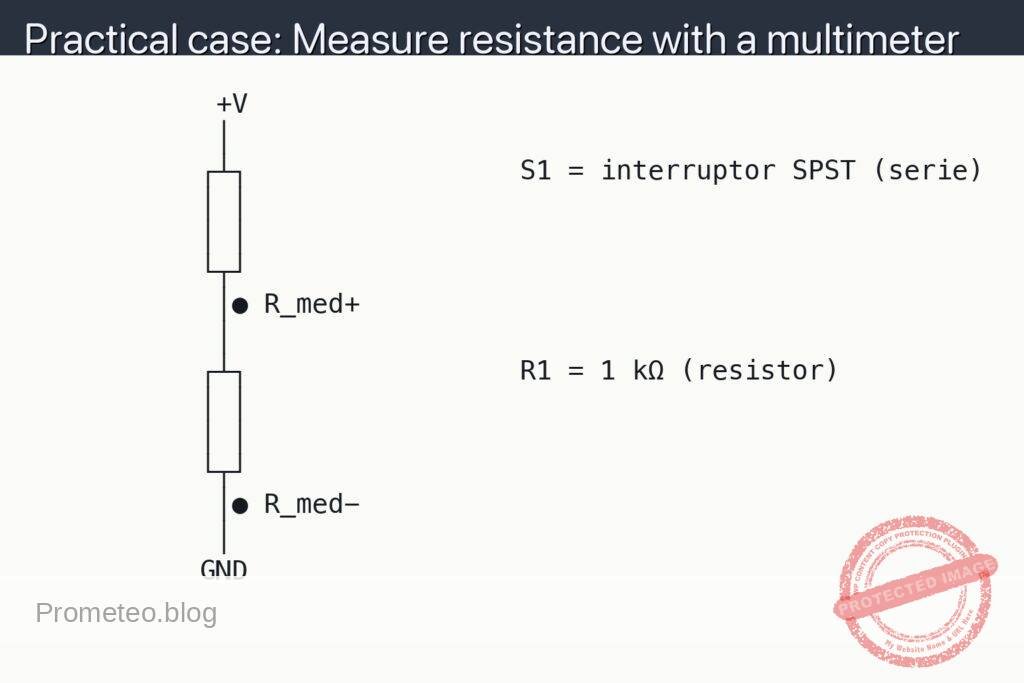
- Measure the voltage V_CC (supply voltage between +12 V and GND) with switch S1 open and closed; it should remain close to 12 V in both cases.
- Measure the voltage V_CARGA (between node VCARGA and GND) with the switch closed; it should be very close to 12 V (ideally 12 V, it may be slightly less depending on the supply).
- Check that resistor R1 gets moderately warm but not excessively hot after several minutes of continuous operation.
-
Measuring the spark and the effect of the capacitor (qualitative observation):
- First disconnect capacitor C1 (100 µF) from the circuit and toggle S1 several times, watching the spark between the contacts (in an environment that is not very bright, always safely: do not bring your face close to the contacts).
- Reconnect C1 and repeat the test; you should notice a visible reduction in the intensity of the spark when opening/closing S1.
- Also connect C2 (100 nF) and observe whether there is any additional change in the spark (it usually helps mainly with very fast transients).
-
Measuring V_CARGA over time (if you have a multimeter with “Hold” function or, better, an oscilloscope):
- V_CARGA means “voltage on the load”: measure between node VCARGA and GND.
- Close switch S1 and check that V_CARGA ≈ 12 V in steady state.
- With the oscilloscope, connect the probe tip to node VCARGA and the ground clip to GND; set the time base in the range of 5–20 ms/div.
- Open S1 and observe how long it takes V_CARGA to fall from 12 V to 0 V; with the capacitor connected there should be a somewhat smoother fall compared to the case without capacitor (exponential curve instead of an almost instantaneous drop).
-
Measuring current in the load (if your multimeter can measure DC current):
- Disconnect one of the wires between S1 and R1 and put the multimeter in ammeter mode in series, measuring between the output node of S1 (VCARGA) and resistor R1.
- I_CARGA will be the current flowing through R1; for 12 V and 100 Ω you expect around 120 mA (I_CARGA ≈ 0.12 A).
- Check that when you close S1 the current rises to that value and when you open it the current falls to 0 A; with the capacitor connected, the drop may not be absolutely instantaneous (depending on the sensitivity of the meter).
Educational explanation (what is happening)
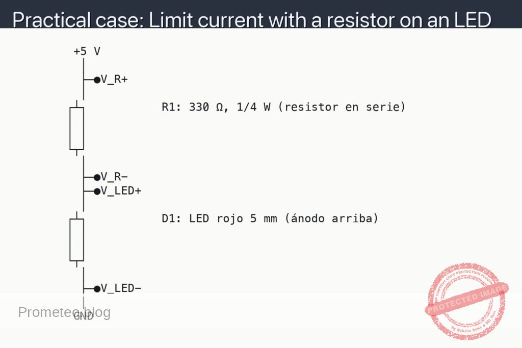
- Switch S1 opens and closes the current path to the load (R1).
- When you open the switch without a capacitor, the current is cut off very abruptly and the energy stored in the load and wiring can produce a small voltage spike and spark.
- Capacitor C1, connected between the load node (VCARGA) and GND, acts as a small energy “storage” that:
- Charges when the switch is closed.
- Discharges when the switch is opened, delivering current for a short time.
- Because of this discharge, the voltage does not drop to 0 V suddenly; the transition is smoother and the energy available to form a spark at the contacts is reduced.
- The ceramic capacitor C2 (100 nF) has a much smaller capacitance value but responds very quickly to abrupt changes, helping to filter very high-frequency spikes.
Common mistakes
- Incorrect polarity of the electrolytic capacitor:
- Connecting it reversed (+ to GND and – to node VCARGA) can damage it; always check the “+” marks or the “–” stripe.
- Underestimating the working voltage of the capacitor:
- Do not use 10 V capacitors in a 12 V circuit. Always choose a safety margin (at least 25 V in this case).
- Forgetting the power dissipation of the load resistor:
- With 12 V and 100 Ω, the power dissipated is P ≈ V²/R = 144/100 = 1.44 W; a 5 W resistor is suitable, but a 1/4 W resistor will burn out.
- Creating a direct short circuit:
- Do not connect the capacitor directly between +12 V and GND without the load, if it is not intended; although it is usually not dangerous for small values, it can produce high peak currents.
Safety and good practices
- Always work with the power supply disconnected while you are assembling or modifying connections first.
- Do not touch exposed terminals directly while you operate the switch, even at low voltage.
- Leave space around the 5 W resistor so it can dissipate heat; do not rest it on flammable materials.
- If the capacitor gets hot, swells, or emits a strange smell, disconnect the supply immediately and check polarity and rated voltage.
Possible improvements and extensions
- Replace resistor R1 with a small 12 V relay to see how the capacitor helps reduce sparks when disconnecting coils.
- Try different values for C1 (10 µF, 47 µF, 220 µF) and compare how much the duration of the V_CARGA decay changes.
- Add a diode in parallel with an inductive load (if you use a relay instead of R1) and observe how diode + capacitor further reduce spikes and sparks.
- Measure the RC time constant in more detail and experimentally verify the theoretical formula τ = R × C.
More Practical Cases at Prometeo.blog
Find this product and/or books on this topic on Amazon
As an Amazon affiliate, I earn from qualifying purchases. If you buy through this link, you help keep this project going.
Quick quiz
More Practical Cases on Prometeo.blog

Telecommunications Electronics Engineer and Computer Engineer (official degrees in Spain).