Introduction
Every time I teach about inductors, I recall a student who struggled to grasp their function. One day, while experimenting with a simple circuit, the lightbulb moment happened. It was fascinating to see how a component could store energy in a magnetic field, transforming the way they approached electronics. Inductors are not just passive components; they are vital players in the realm of electrical engineering and circuit design. They can be found in various applications, from power supplies to radio frequency circuits, and understanding their behavior is essential for anyone interested in electronics. In this tutorial, we will delve deeper into the world of inductors, exploring their functions, applications, and how to build a practical project that showcases their utility.
What it’s used for and how it works
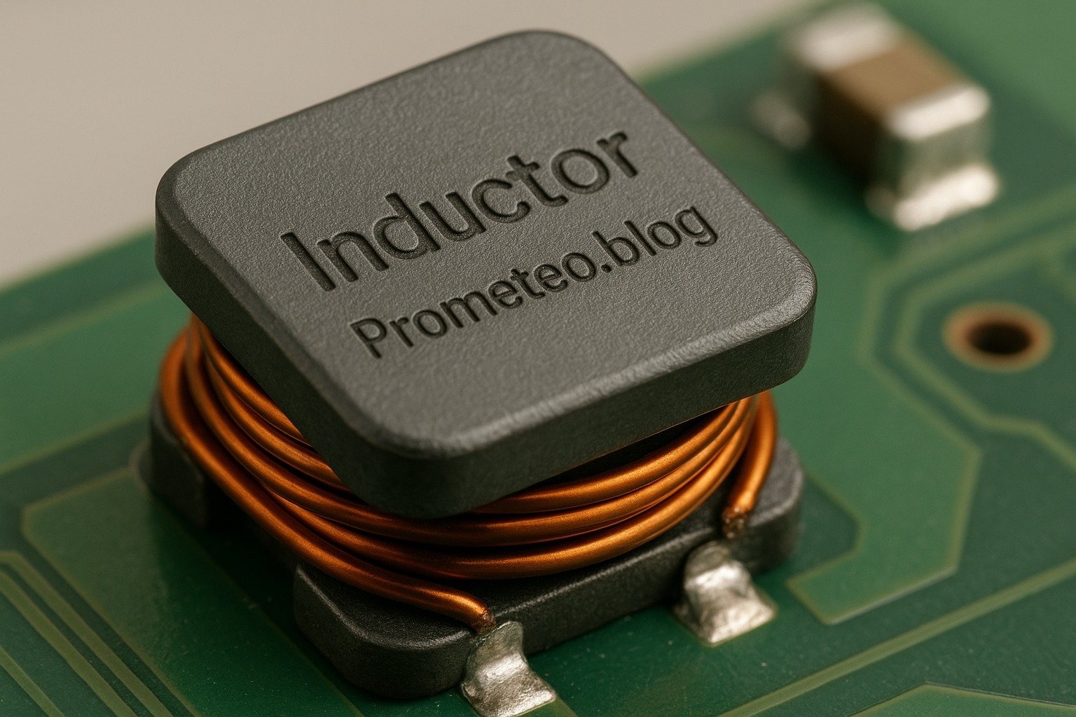
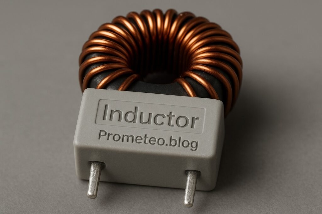
Inductors are passive electrical components that store energy in a magnetic field when electrical current passes through them. They are widely used in various applications, including filters, transformers, energy storage devices, and oscillators. Understanding how inductors work is crucial for any electronics enthusiast or engineer.
Basic Principle
The basic principle of an inductor is Faraday’s Law of Electromagnetic Induction, which states that a changing magnetic field within a closed loop induces an electromotive force (EMF) in that loop. When current flows through an inductor, it creates a magnetic field around it. If the current changes, the magnetic field also changes, inducing a voltage that opposes the change in current. This phenomenon is known as self-inductance and is a fundamental concept in electromagnetism.
To illustrate this with an example, consider a simple circuit with a battery and an inductor. When the circuit is first closed, the inductor resists the sudden increase in current due to its magnetic field. This resistance to change results in a gradual increase in current over time, rather than an instantaneous jump. The time it takes for the current to reach its maximum value is determined by the inductance of the inductor and the resistance in the circuit.
Inductance
Inductance is the property of an inductor that quantifies its ability to store energy in the magnetic field. It is measured in henries (H). The inductance value depends on several factors, such as the number of turns in the coil, the core material, and the physical dimensions of the coil. Higher inductance means a greater ability to store energy. For instance, a coil with more turns will have a higher inductance than a coil with fewer turns, all else being equal.
Inductance can also be influenced by the core material used in the inductor. Ferromagnetic materials, such as iron, can significantly increase the inductance compared to air-core inductors. This is due to the higher magnetic permeability of these materials, which enhances the magnetic field created by the current flowing through the coil.
Applications of Inductors
-
Energy Storage: Inductors are commonly used in power supplies and converters to temporarily store energy and smooth out voltage levels. They help manage fluctuations in current, ensuring stable operation. For example, in a switching power supply, inductors can store energy during the «on» phase and release it during the «off» phase, maintaining a steady output voltage.
-
Filters: Inductors are employed in LC (inductor-capacitor) filters to allow certain frequencies to pass while blocking others. They are essential in radio frequency (RF) applications, audio systems, and communication devices. For instance, in a low-pass filter, the inductor blocks high-frequency signals while allowing lower frequencies to pass, which is crucial in audio processing to eliminate unwanted noise.
-
Transformers: In transformers, inductors are used to transfer energy between circuits through electromagnetic induction. They enable voltage transformation, allowing efficient energy distribution. A transformer consists of two inductors (primary and secondary) wound around a common core. When alternating current flows through the primary inductor, it creates a changing magnetic field that induces a voltage in the secondary inductor.
-
Oscillators: Inductors play a vital role in oscillator circuits by providing the necessary reactance to produce oscillations at specific frequencies. In a tank circuit, which consists of an inductor and a capacitor, the energy oscillates between the magnetic field of the inductor and the electric field of the capacitor, resulting in a sustained oscillation at a resonant frequency.
-
Chokes: Inductors are used as chokes to limit the amount of AC current flowing in a circuit, filtering out unwanted signals while allowing DC signals to pass. This is particularly useful in power supply circuits, where it is essential to suppress high-frequency noise that can interfere with the operation of sensitive components.
Behavior in Circuits
When an inductor is connected to a DC power supply, it initially resists the change in current, which leads to a gradual increase in current over time. This behavior is characterized by the time constant, which is determined by the inductance and the resistance in the circuit. The time constant (τ) can be calculated using the formula:
τ = L / R
where L is the inductance in henries and R is the resistance in ohms. Eventually, the current stabilizes, and the inductor behaves like a short circuit, allowing the maximum current to flow.
In an AC circuit, the behavior of inductors is different. They introduce reactance, which is frequency-dependent. The inductive reactance ( X(L) ) can be calculated using the formula:
X(L) = 2πfL
where f is the frequency in hertz and L is the inductance in henries. As the frequency of the AC signal increases, the inductive reactance also increases, leading to less current flow. This property is exploited in filter circuits to allow certain frequencies to pass while blocking others.
For example, in a high-pass filter, an inductor is used to block low-frequency signals while allowing high-frequency signals to pass. Conversely, in a low-pass filter, an inductor is used to allow low-frequency signals to pass while blocking high-frequency signals.
Conclusion
In summary, inductors are essential components in the world of electronics. They offer a unique ability to store energy in a magnetic field and are used in various applications, from power supplies to communication systems. Understanding their function and behavior is fundamental for anyone working with electrical circuits. By grasping the principles of inductance and the applications of inductors, you can enhance your skills and knowledge in electronics significantly.
Key parameters
| Parameter | Typical | Range | Unit | Note |
|---|---|---|---|---|
| Inductance | 10 | 1 – 10000 | H | Common in power applications |
| DC Resistance | 0.5 | 0.01 – 50 | Ω | Affects efficiency |
| Saturation Current | 1.5 | 0.1 – 15 | A | Maximum current before saturation |
| Quality Factor (Q) | 30 | 5 – 200 | — | Indicates efficiency |
| Self-Resonant Frequency | 100 kHz | 1 kHz – 10 MHz | Hz | Frequency at which it resonates |
The table above summarizes the key parameters associated with inductors. Each parameter plays a vital role in determining the performance and suitability of an inductor for a specific application. For instance, the quality factor (Q) indicates how efficiently an inductor can store and release energy, with higher values representing better performance. Understanding these parameters is crucial when selecting inductors for your projects.
Hands-on practical project: Building a Simple LC Filter
Goal: Create a low-pass LC filter to attenuate high frequencies in an audio signal, verifying that the output signal is lower than -3 dB at 1 kHz.
Estimated time: 45 minutes
Materials
- 1 × Inductor — 10 mH for the filter circuit.
- 1 × Capacitor — 100 µF for coupling the signals.
- 1 × Audio source — Any device with an audio output.
- 1 × Audio amplifier — For output sound amplification.
- 2 × 3.5 mm audio cables — To connect audio source and amplifier.
- 1 × Breadboard — For assembling the circuit.
- 2 × Jumper wires (red and black) — To make connections.
- 1 × Multimeter — To measure output levels.
Step-by-step build
- Set Up the Breadboard: Start by placing the inductor and capacitor on the breadboard. Ensure they are easily accessible for connections. The inductor should be connected in series with the audio source while the capacitor will be connected to ground.
-
Check: Ensure components are firmly seated on the breadboard. A loose connection can lead to inconsistent performance.
-
Connect the Inductor: Connect one terminal of the inductor to the audio source’s output. Connect the other terminal of the inductor to one terminal of the capacitor. This configuration allows the inductor to pass low frequencies while blocking higher ones.
-
Check: Verify that connections are secure, as any loose wires can disrupt the signal flow.
-
Connect the Capacitor: Connect the second terminal of the capacitor to the ground rail of the breadboard. This completes the LC filter circuit, allowing it to operate effectively.
-
Check: Ensure the capacitor is oriented correctly; polarity matters unless it’s a non-polarized type. An incorrectly oriented capacitor can fail and potentially damage the circuit.
-
Connect the Output: Use jumper wires to connect the output of the LC filter to the audio amplifier’s input. This will allow you to hear the filtered audio signal. Make sure to check the right input channel on the amplifier.
-
Check: Confirm that connections are made to the correct terminals to ensure proper signal routing.
-
Power Up the Circuit: Once everything is connected, power up the audio source and the amplifier to begin the testing phase. Adjust the volume on the audio source to ensure a clear signal is being sent.
-
Check: Listen for audio output; there should be no distortion. If distortion occurs, check the connections and component ratings.
-
Measure Output Levels: Use the multimeter to measure the output voltage of the audio signal at the amplifier. Adjust the frequency of the audio source to verify the -3 dB point at 1 kHz. Note the changes in output signal as the frequency varies.
- Check: Make sure the multimeter is set to the correct mode for AC voltage. Accurate measurements are crucial for validating the filter’s performance.
Testing and validation
- Frequency Sweep: Connect a function generator to the input of the LC filter and sweep through frequencies from 100 Hz to 10 kHz. Monitor the output level on the multimeter and note when the output drops below -3 dB.
-
Check: Document the specific frequencies where the output drops significantly, as this will help you understand the filter’s cutoff characteristics.
-
Listen to the Filtered Audio: Play music through the audio source and listen to the output from the amplifier. The high frequencies should be attenuated, resulting in a more bass-heavy sound.
- Check: Verify that the sound quality matches your expectations. If the high frequencies are still present, recheck your connections and component values.
Extend the project
- Experiment with different inductor and capacitor values to change cutoff frequencies. This will provide insight into how component values affect filter performance.
- Implement a potentiometer to adjust the resistance and fine-tune the filter. This addition allows for more dynamic control over the cutoff frequency.
- Add a second filter stage for sharper frequency attenuation. By cascading filters, you can create more complex filtering effects.
Safety
- Always ensure that the circuit is powered off when making adjustments. This precaution helps prevent accidental shocks or component damage.
- Avoid touching live wires during operation to prevent shocks. Use insulated tools when necessary.
- Keep components within their specified ratings to prevent overheating. Exceeding ratings can lead to component failure and potentially dangerous situations.
Common mistakes and how to avoid them
- Incorrect Polarity: Ensure capacitors are connected with the correct polarity to avoid circuit failure. Always check the markings on the capacitor to identify the positive and negative leads.
- Loose Connections: Double-check all wire connections to prevent intermittent signals. A loose connection can lead to unpredictable circuit behavior.
- Overloading Components: Verify that components are rated for the expected voltage and current levels. Using components beyond their ratings can cause overheating and failure.
- Ignoring Inductor Ratings: Make sure the inductor’s saturation current is not exceeded during operation. Exceeding this limit can lead to a loss of inductance and circuit malfunction.
- Neglecting Ground Connections: Always provide a proper ground connection to avoid circuit malfunction. A floating ground can cause erratic behavior and signal integrity issues.
Conclusion
Inductors are pivotal in many electronic applications, from filtering signals to energy storage. By understanding how they work and implementing practical projects, you can enhance your knowledge and skills in electronics. I encourage you to explore different configurations and applications. Embrace the learning process and experiment with inductors in your circuits. The journey of discovery in electronics is continuous, and each project brings you closer to mastery. More information at prometeo.blog
Third-party readings
- Inductores: Teoría y Principio de Funcionamiento | Open Video
- Inductor basics – ¿Qué es un inductor? | Afrotechmods – Diversión con la electrónica
- Inductores Explicados – The Engineering Mindset
Find this product and/or books on this topic on Amazon
As an Amazon Associate, I earn from qualifying purchases. If you buy through this link, you help keep this project running.
Quick Quiz


