
Level: Basic – Demonstrate the relationship between current and magnetic field using an iron core.
Objective and use case
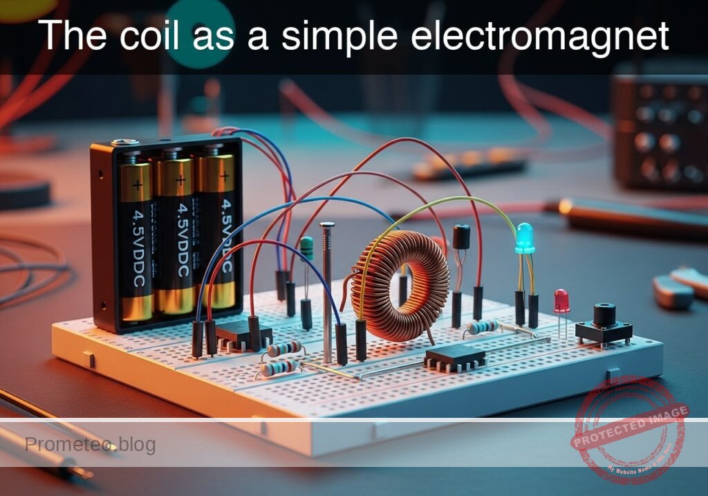
In this experiment, you will build a functional electromagnet by winding insulated copper wire around a ferromagnetic core (iron nail or bolt) and powering it with a DC source.
- Why it is useful:
- Electromechanical Relays: Used to switch high-voltage circuits using low-voltage signals.
- Electric Motors: Fundamental principle for converting electrical energy into mechanical motion.
- Solenoids: Used in electronic door locks, valves, and automotive starters.
- Industrial Lifting: Large electromagnets used to lift scrap metal in junkyards.
- Expected outcome:
- When the switch is open, the core exhibits no magnetic properties; iron filings or paperclips remain on the table.
- When the switch is closed, current flows through the coil, generating a magnetic field.
- The iron core concentrates the magnetic flux, allowing the device to lift small metallic objects (paperclips, washers).
- Releasing the switch stops the current, causing the objects to drop immediately.
- Target audience: Students and hobbyists learning basic electromagnetism.
Materials
- V1: 4.5 V DC Battery pack (3x AA batteries), function: energy source.
- S1: Momentary Push-button Switch (NO), function: current control.
- L1: Solenoid Coil (approx. 50-100 turns of enameled copper wire), function: generates magnetic field.
- CORE: Large Iron Nail or Bolt (Soft Iron), function: magnetic core for L1.
- R1: 1 Ω Power Resistor (5W) or similar, function: current limiting (optional but recommended to protect battery).
- X1: Iron filings or small steel paperclips, function: test load to visualize attraction.
Wiring guide
- V1 (Positive): Connects to node
VCC. - V1 (Negative): Connects to node
0(GND). - S1: Connects between node
VCCand nodeSW_OUT. - R1: Connects between node
SW_OUTand nodeCOIL_IN. - L1: Connects between node
COIL_INand node0(GND).- Note: The wire for L1 must be physically wrapped tightly around the CORE.
Conceptual block diagram
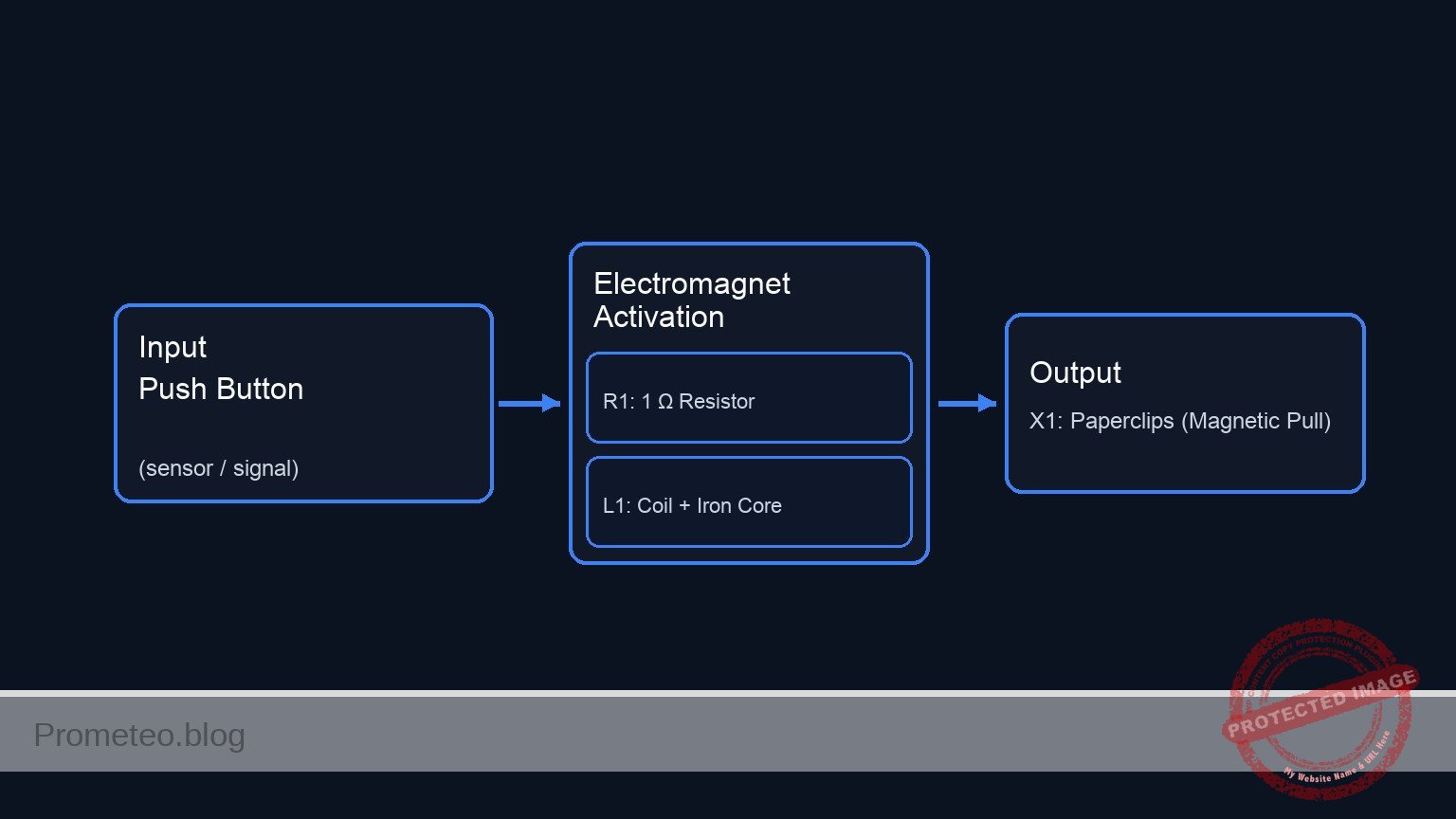
Schematic
[ V1: 4.5 V Battery ] --(VCC)--> [ S1: Push Button ] --(SW_OUT)--> [ R1: 1 Ω Resistor ] --(COIL_IN)--> [ L1: Coil + Iron Core ] --> GND
                                                                                                                |
                                                                                                         (Magnetic Field)
                                                                                                                |
                                                                                                                V
                                                                                                       [ X1: Paperclips ]
Measurements and tests
- Baseline Check: Before connecting the battery, place the CORE (with the wire wrapped around it) near the iron filings (X1). Confirm there is no attraction.
- Activation: Press and hold S1 to close the circuit.
- Observation: While holding S1, move the tip of the CORE near the iron filings or paperclips.
- Verification: Observe that the metal objects stick to the CORE.
- Deactivation: Release S1. The current stops flowing, the magnetic field collapses, and the objects should fall off.
- Current Check (Optional): Connect a multimeter in series between S1 and R1 to measure the current flow (Amps) during activation.
SPICE netlist and simulation
Reference SPICE Netlist (ngspice) — excerptFull SPICE netlist (ngspice)
* Practical case: The coil as a simple electromagnet
.width out=256

* --- Power Source ---
* V1: 4.5 V DC Battery pack (3x AA batteries)
V1 VCC 0 DC 4.5

* --- Control Signal for Switch S1 ---
* Simulates the user pressing the button (S1).
* Logic: 0V (Released) -> 5V (Pressed).
* Timing: Press at 1ms, hold for 50ms, release.
V_S1_CTRL S1_GATE 0 PULSE(0 5 1m 1u 1u 50m 100m)

* --- Circuit Components ---

* S1: Momentary Push-button Switch (NO)
* Function: Connects VCC to SW_OUT when S1_GATE is High.
S1 VCC SW_OUT S1_GATE 0 SW_MODEL

* R1: 1 Ohm Power Resistor
* ... (truncated in public view) ...
Copy this content into a .cir file and run with ngspice.
* Practical case: The coil as a simple electromagnet
.width out=256

* --- Power Source ---
* V1: 4.5 V DC Battery pack (3x AA batteries)
V1 VCC 0 DC 4.5

* --- Control Signal for Switch S1 ---
* Simulates the user pressing the button (S1).
* Logic: 0V (Released) -> 5V (Pressed).
* Timing: Press at 1ms, hold for 50ms, release.
V_S1_CTRL S1_GATE 0 PULSE(0 5 1m 1u 1u 50m 100m)

* --- Circuit Components ---

* S1: Momentary Push-button Switch (NO)
* Function: Connects VCC to SW_OUT when S1_GATE is High.
S1 VCC SW_OUT S1_GATE 0 SW_MODEL

* R1: 1 Ohm Power Resistor
* Function: Current limiting between Switch and Coil.
R1 SW_OUT COIL_IN 1

* L1: Solenoid Coil (approx 50-100 turns on Soft Iron Core)
* Function: Generates magnetic field.
* Value: 5mH (Estimated for described coil).
L1 COIL_IN 0 5m

* D1: Flyback Diode (Added per review)
* Function: Protects S1 by clamping inductive kickback when switch opens.
* Connection: Anode to GND (0), Cathode to COIL_IN.
D1 0 COIL_IN D_1N4007

* --- Models ---
* Switch Model: Low resistance ON, High resistance OFF.
.model SW_MODEL sw (vt=2.5 vh=0.2 ron=0.05 roff=100Meg)

* Diode Model: Standard Silicon Rectifier (1N4007).
.model D_1N4007 D (IS=2.5n RS=0.04 N=1.7 BV=1000 IBV=5u)

* --- Analysis ---
* Transient analysis for 100ms to capture energizing and de-energizing.
.tran 10u 100m
.op

* --- Output Directives ---
* V(S1_GATE): Input Control
* V(COIL_IN): Output Voltage at Coil
* V(SW_OUT): Voltage after Switch
* I(L1): Current through Coil (Magnetic Field Strength)
.print tran V(S1_GATE) V(COIL_IN) V(SW_OUT) I(L1)

.end
Simulation Results (Transient Analysis)

Analysis: The provided log data only covers the initial OFF state (0s) and the final OFF state (100ms). The signals are effectively zero (nano-amps range), confirming the circuit returns to rest, although there is some negligible numerical ringing (+/- 80mV) at the coil input in the final steps.
Show raw data table (10053 rows)
Index   time            v(s1_gate)      v(coil_in)      v(sw_out)       l1#branch
0	0.000000e+00	0.000000e+00	0.000000e+00	4.500000e-08	4.500000e-08
1	1.000000e-07	0.000000e+00	-1.58289e-19	4.500000e-08	4.500000e-08
2	2.000000e-07	0.000000e+00	-1.58289e-19	4.500000e-08	4.500000e-08
3	4.000000e-07	0.000000e+00	-1.58289e-19	4.500000e-08	4.500000e-08
4	8.000000e-07	0.000000e+00	-2.44581e-19	4.500000e-08	4.500000e-08
5	1.600000e-06	0.000000e+00	3.684064e-19	4.500000e-08	4.500000e-08
6	3.200000e-06	0.000000e+00	-3.03688e-19	4.500000e-08	4.500000e-08
7	6.400000e-06	0.000000e+00	2.882625e-19	4.500000e-08	4.500000e-08
8	1.280000e-05	0.000000e+00	-3.16655e-19	4.500000e-08	4.500000e-08
9	2.280000e-05	0.000000e+00	2.975540e-19	4.500000e-08	4.500000e-08
10	3.280000e-05	0.000000e+00	-3.05533e-19	4.500000e-08	4.500000e-08
11	4.280000e-05	0.000000e+00	2.975540e-19	4.500000e-08	4.500000e-08
12	5.280000e-05	0.000000e+00	-3.05533e-19	4.500000e-08	4.500000e-08
13	6.280000e-05	0.000000e+00	2.975540e-19	4.500000e-08	4.500000e-08
14	7.280000e-05	0.000000e+00	-3.05533e-19	4.500000e-08	4.500000e-08
15	8.280000e-05	0.000000e+00	2.975540e-19	4.500000e-08	4.500000e-08
16	9.280000e-05	0.000000e+00	-3.05533e-19	4.500000e-08	4.500000e-08
17	1.028000e-04	0.000000e+00	2.975540e-19	4.500000e-08	4.500000e-08
18	1.128000e-04	0.000000e+00	-3.05533e-19	4.500000e-08	4.500000e-08
19	1.228000e-04	0.000000e+00	2.975540e-19	4.500000e-08	4.500000e-08
20	1.328000e-04	0.000000e+00	-3.05533e-19	4.500000e-08	4.500000e-08
21	1.428000e-04	0.000000e+00	2.975540e-19	4.500000e-08	4.500000e-08
22	1.528000e-04	0.000000e+00	-3.05533e-19	4.500000e-08	4.500000e-08
23	1.628000e-04	0.000000e+00	2.975540e-19	4.500000e-08	4.500000e-08
... (10029 more rows) ...
Common mistakes and how to avoid them
- Overheating the battery/wire: Creating a coil with very low resistance (short wire) draws excessive current. Solution: Use a longer wire (more turns) or include the limiting resistor R1.
- Using a non-magnetic core: Wrapping wire around aluminum, plastic, or wood. Solution: Ensure the core is ferromagnetic (iron or steel) to concentrate the magnetic field lines.
- Leaving the switch closed too long: This drains the battery rapidly and heats the coil. Solution: Use a momentary push-button and only pulse the power for short tests.
Troubleshooting
- Symptom: No magnetic attraction when switch is pressed.
- Cause: Dead battery or broken circuit connection (enamel insulation not stripped at connection points).
- Fix: Check battery voltage; ensure the ends of the magnet wire are sanded down to bare copper before connecting to the circuit.
- Symptom: Very weak magnetic pull.
- Cause: Too few turns on the coil or low current.
- Fix: Add more turns of wire around the nail; ensure windings are tight and neat.
- Symptom: Wire gets extremely hot immediately.
- Cause: Short circuit condition (resistance too low).
- Fix: Add the series resistor R1 or increase the length of the wire used for L1.
Possible improvements and extensions
- Variable Strength: Add a potentiometer (rheostat) in series to vary the current and observe how the lifting capacity changes (number of paperclips lifted).
- Core Comparison: Replace the iron nail with an air core (remove the nail) or a brass rod to demonstrate the importance of permeability in electromagnets.
More Practical Cases on Prometeo.blog
Find this product and/or books on this topic on Amazon
As an Amazon Associate, I earn from qualifying purchases. If you buy through this link, you help keep this project running.
Quick Quiz

Carlos Núñez Zorrilla
Electronics & Computer Engineer
Telecommunications Electronics Engineer and Computer Engineer (official degrees in Spain).

