
Level: Medium – Disconnect a critical load using a normally closed relay contact when a voltage threshold is exceeded.
Objective and use case
In this practical case, you will build a hardware-based overvoltage protection circuit. It uses a Zener diode to set a voltage threshold and a bipolar junction transistor (BJT) to actuate an electromechanical relay, mechanically disconnecting power when the voltage spikes to dangerous levels.
This topology is highly useful in real-world scenarios:
– Safeguarding sensitive 5 V microcontrollers from accidental power supply surges.
– Protecting expensive sensors or instruments in automotive environments where alternator spikes occur.
– Ensuring battery-powered or USB-powered devices mechanically cut out during a charger regulator failure.
Expected outcome:
– When the input voltage (v-in) is in the safe range (e.g., 5.0 V), the BJT remains off, the relay is unpowered, and the normally closed (NC) contact feeds power to the load.
– When v-in exceeds the Zener threshold plus the BJT base-emitter drop (around 6.3 V), the Zener conducts.
– Base current flows, the BJT switch turns on, and the relay coil energizes.
– The relay’s NC contact opens, triggering a v-load-disconnect event that drops the load voltage to 0 V.
– Target audience and level: Intermediate electronics students exploring analog voltage thresholds and electromechanical switching.
Materials
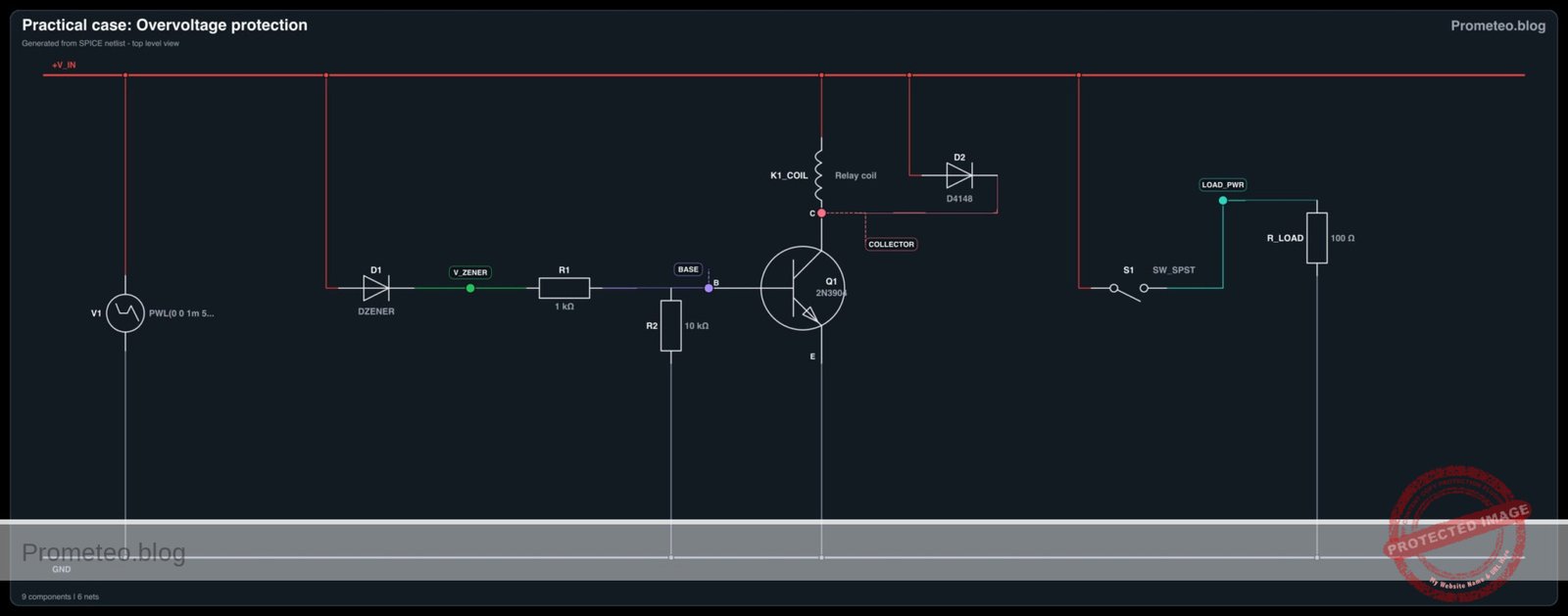
V1: Variable DC supply (0-9 V), function: provides system input voltage (v-in)D1: 5.6 V Zener diode (e.g., 1N4734 A), function: sets the overvoltage threshold referenceR1: 1 kΩ resistor, function: base current limiting for the BJTR2: 10 kΩ resistor, function: base pull-down to ensure the BJT turns off cleanlyQ1: 2N3904 NPN transistor, function: relay driver switchD2: 1N4148 or 1N4007 diode, function: flyback protection for the relay coilK1: 5 V SPDT Relay, function: disconnects the load using its normally closed (NC) contactR_LOAD: 100 Ω resistor, function: simulated critical load
Wiring guide
V1: positive terminal connects to nodeV_IN, negative terminal connects to node0(GND).D1: cathode connects to nodeV_IN, anode connects to nodeV_ZENER.R1: connects between nodeV_ZENERand nodeBASE.R2: connects between nodeBASEand node0.Q1: collector connects to nodeCOLLECTOR, base connects to nodeBASE, emitter connects to node0.K1_COIL: the relay coil connects between nodeV_INand nodeCOLLECTOR.D2: cathode connects to nodeV_IN, anode connects to nodeCOLLECTOR(wired anti-parallel to the relay coil).K1_COM: the relay’s common contact connects to nodeV_IN.K1_NC: the relay’s normally closed contact connects to nodeLOAD_PWR.R_LOAD: connects between nodeLOAD_PWRand node0.
Conceptual block diagram
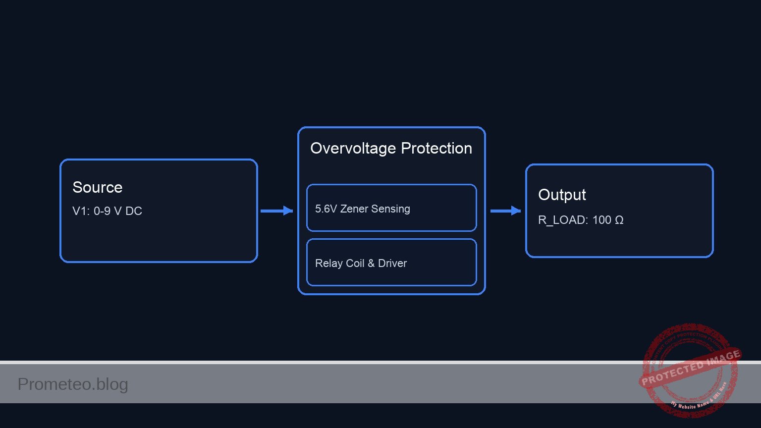
Schematic
POWER SOURCE:
[ V1: 0-9 V DC ] --(V_IN)--> System Power
[ V1: Negative ] ---------> GND

1. OVERVOLTAGE SENSING & CONTROL PATH:
V_IN --> [ D1: 5.6 V Zener ] --(V_ZENER)--> [ R1: 1 kΩ ] --(BASE)--> [ Q1:Base ]
                                                             |
                                                        [ R2: 10 kΩ ]
                                                             |
                                                            GND

2. RELAY COIL & DRIVER PATH:
V_IN --> [ K1_COIL || D2: Flyback(Rev) ] --(COLLECTOR)--> [ Q1:Collector ]
                       |                                        |
                (Magnetic Link)                            [ Q1:Emitter ]
                       |                                        |
                       v                                       GND

3. PROTECTED LOAD PATH:
V_IN --> [ K1_COM ] --(Normally Closed)--> [ K1_NC ] --(LOAD_PWR)--> [ R_LOAD: 100 Ω ] --> GND
Electrical diagram
Measurements and tests
- Set the variable power supply
V1to exactly 5.0 V. - Measure
v-inrelative to ground. Verify it is 5.0 V. - Measure the voltage across the load (
LOAD_PWRto0). It should read 5.0 V, indicating the relay is deactivated and the NC contact is closed. - Slowly increase the voltage of
V1. Monitorv-zener(the voltage at the anode ofD1). It will remain near 0 V untilv-incrosses the ~5.6 V breakdown threshold of the Zener diode. - Push
V1up to 6.5 V. Observe thatv-zenerrises, pushing current into the base ofQ1. - Verify the
v-load-disconnectevent: listen for the relay click. Measure the voltage atLOAD_PWR; it should instantly drop to 0 V as the NC contact opens, successfully protecting the load.
SPICE netlist and simulation
Reference SPICE Netlist (ngspice) — excerptFull SPICE netlist (ngspice)
* Practical case: Overvoltage protection
.width out=256

* Input Voltage Source (Sweeps from 0V to normal 5V, then overvoltage 9V, then back)
V1 V_IN 0 PWL(0 0 1m 5 4m 5 5m 9 6m 9 7m 5 9m 5 10m 0)

* Zener Diode for threshold detection
D1 V_IN V_ZENER DZENER

* Base resistors for Q1
R1 V_ZENER BASE 1k
R2 BASE 0 10k

* Relay Driver Transistor
Q1 COLLECTOR BASE 0 2N3904

* Relay Coil (Modeled as series inductor and resistor)
L_K1_COIL V_IN K1_COIL_INT 10m
R_K1_COIL K1_COIL_INT COLLECTOR 100

* ... (truncated in public view) ...
Copy this content into a .cir file and run with ngspice.
* Practical case: Overvoltage protection
.width out=256

* Input Voltage Source (Sweeps from 0V to normal 5V, then overvoltage 9V, then back)
V1 V_IN 0 PWL(0 0 1m 5 4m 5 5m 9 6m 9 7m 5 9m 5 10m 0)

* Zener Diode for threshold detection
D1 V_IN V_ZENER DZENER

* Base resistors for Q1
R1 V_ZENER BASE 1k
R2 BASE 0 10k

* Relay Driver Transistor
Q1 COLLECTOR BASE 0 2N3904

* Relay Coil (Modeled as series inductor and resistor)
L_K1_COIL V_IN K1_COIL_INT 10m
R_K1_COIL K1_COIL_INT COLLECTOR 100

* Flyback Diode
D2 V_IN COLLECTOR D4148

* Relay Normally Closed (NC) Contact
* Modeled as a voltage-controlled switch controlled by the coil voltage (V_IN - COLLECTOR)
* When Q1 is OFF, coil voltage is 0V -> Switch is CLOSED (roff = 0.1)
* When Q1 is ON, coil voltage is > 6V -> Switch is OPEN (ron = 100meg)
S1 V_IN LOAD_PWR V_IN COLLECTOR RelayNC

* Critical Load
R_LOAD LOAD_PWR 0 100

* Models
.model DZENER D(IS=1e-15 RS=10 N=1 BV=5.6 IBV=5m)
.model D4148 D(IS=1e-14 RS=0.1 N=1)
.model 2N3904 NPN(IS=1E-14 VAF=100 BF=300 IKF=0.4 XTB=1.5 BR=4 CJC=4E-12 CJE=8E-12 RB=20 RC=0.1 RE=0.1 TR=250E-9 TF=350E-12 ITF=1 VTF=2 XTF=3)
.model RelayNC SW(vt=3 vh=0.5 ron=100meg roff=0.1)

* Simulation Directives
.print tran V(V_IN) V(LOAD_PWR) V(BASE) V(COLLECTOR) V(V_ZENER) I(L_K1_COIL)
.tran 10u 10m
.op
.end
Simulation Results (Transient Analysis)

Show raw data table (1788 rows)
Index   time            v(v_in)         v(load_pwr)     v(base)         v(collector)    v(v_zener)      l_k1_coil#branc
0	0.000000e+00	0.000000e+00	0.000000e+00	4.369907e-29	1.104363e-28	4.276684e-29	-1.10436e-30
1	1.000000e-07	5.000000e-04	4.995005e-04	2.124049e-05	1.169502e-04	2.124049e-05	3.826672e-09
2	1.128896e-07	5.644481e-04	5.638843e-04	2.436647e-05	1.341994e-04	2.436647e-05	4.380682e-09
3	1.386689e-07	6.933444e-04	6.926518e-04	3.144704e-05	1.734710e-04	3.144704e-05	5.604067e-09
4	1.902274e-07	9.511370e-04	9.501868e-04	5.084817e-05	2.848367e-04	5.084817e-05	8.658258e-09
5	2.933444e-07	1.466722e-03	1.465257e-03	1.084331e-04	6.633002e-04	1.084332e-04	1.622310e-08
6	4.910392e-07	2.455196e-03	2.452743e-03	2.404937e-04	1.923047e-03	2.404937e-04	2.937980e-08
7	6.875077e-07	3.437539e-03	3.434104e-03	3.216141e-04	3.548938e-03	3.216141e-04	3.345128e-08
8	9.631281e-07	4.815640e-03	4.810829e-03	2.723800e-04	5.450903e-03	2.723800e-04	2.308361e-08
9	1.154824e-06	5.774121e-03	5.768352e-03	1.710095e-04	6.210657e-03	1.710095e-04	1.277625e-08
10	1.305686e-06	6.528429e-03	6.521907e-03	1.116498e-04	6.566319e-03	1.116498e-04	9.181046e-09
11	1.495573e-06	7.477865e-03	7.470395e-03	1.085076e-04	7.080935e-03	1.085076e-04	1.256925e-08
12	1.736950e-06	8.684750e-03	8.676074e-03	1.904626e-04	8.232826e-03	1.904626e-04	2.277129e-08
13	2.001986e-06	1.000993e-02	9.999931e-03	2.728041e-04	1.002166e-02	2.728041e-04	2.853663e-08
14	2.256607e-06	1.128304e-02	1.127176e-02	2.568832e-04	1.166727e-02	2.568832e-04	2.342944e-08
15	2.500031e-06	1.250016e-02	1.248767e-02	1.808629e-04	1.277687e-02	1.808630e-04	1.533781e-08
16	2.702903e-06	1.351451e-02	1.350101e-02	1.375223e-04	1.345800e-02	1.375223e-04	1.307538e-08
17	2.944974e-06	1.472487e-02	1.471016e-02	1.562745e-04	1.440894e-02	1.562745e-04	1.754621e-08
18	3.189115e-06	1.594558e-02	1.592965e-02	2.174467e-04	1.574153e-02	2.174467e-04	2.384313e-08
19	3.483820e-06	1.741910e-02	1.740170e-02	2.492948e-04	1.756940e-02	2.492949e-04	2.456373e-08
20	3.789826e-06	1.894913e-02	1.893020e-02	2.050542e-04	1.918736e-02	2.050543e-04	1.855307e-08
21	4.028198e-06	2.014099e-02	2.012087e-02	1.627875e-04	2.016491e-02	1.627876e-04	1.538812e-08
22	4.364653e-06	2.182326e-02	2.180146e-02	1.717346e-04	2.161154e-02	1.717346e-04	1.849039e-08
23	4.749559e-06	2.374779e-02	2.372407e-02	2.249970e-04	2.370014e-02	2.249971e-04	2.340138e-08
... (1764 more rows) ...
Common mistakes and how to avoid them
- Omitting the flyback diode (D2): Failing to place a diode across the relay coil will result in a massive inductive voltage spike when the transistor turns off, permanently destroying the BJT. Always include the anti-parallel diode.
- Installing the Zener diode backward: If the Zener is installed forward-biased (anode to
V_IN), it will act like a standard diode with a 0.7 V drop. The relay will trigger almost immediately. Ensure the cathode faces the positive input. - Wiring the load to the NO contact: If you accidentally connect
R_LOADto the Normally Open (NO) terminal instead of the NC terminal, the load will only receive power during an overvoltage event, which defeats the purpose of the protection circuit.
Troubleshooting
- Symptom: The relay chatters rapidly or buzzes when the input voltage is right at the threshold (e.g., 6.2 V).
- Cause: The circuit lacks hysteresis. A slow-moving analog voltage at the exact threshold causes the BJT to partially turn on, putting the relay in an undefined mechanical state.
- Fix: In a practical setup, overvoltage events are usually fast spikes. For slow-rising voltages, a Schmitt trigger or a latching circuit is required to ensure a clean transition.
- Symptom: The load never powers on, even at 5.0 V.
- Cause: The relay might be stuck energized, the BJT is shorted, or the load was mistakenly wired to the NO contact.
- Fix: Check
LOAD_PWRcontinuity toV_INwhile the circuit is unpowered. ReplaceQ1if it reads a dead short from collector to emitter. - Symptom: The transistor gets exceptionally hot during an overvoltage event.
- Cause: The input voltage was raised far beyond the threshold (e.g., 12 V into a 5 V relay), causing excessive coil current through the BJT.
- Fix: Do not exceed the absolute maximum ratings of the relay coil and the 2N3904 transistor. If higher voltages are expected, use a beefier transistor (like a TIP120) or a pre-regulator.
Possible improvements and extensions
- Add a fault indicator: Connect a red LED with an appropriate current-limiting resistor to the Normally Open (NO) contact. When the overvoltage triggers, the load loses power, and the red LED instantly illuminates to warn the user.
- Implement a mechanical latch: Wire a secondary contact of the relay (if using a DPDT relay) or an SCR in the base circuit so that once an overvoltage event triggers the relay, it stays locked in the «disconnect» state until the user manually presses a reset button, preventing repeated power cycling.
More Practical Cases on Prometeo.blog
Find this product and/or books on this topic on Amazon
As an Amazon Associate, I earn from qualifying purchases. If you buy through this link, you help keep this project running.
Quick Quiz

Telecommunications Electronics Engineer and Computer Engineer (official degrees in Spain).