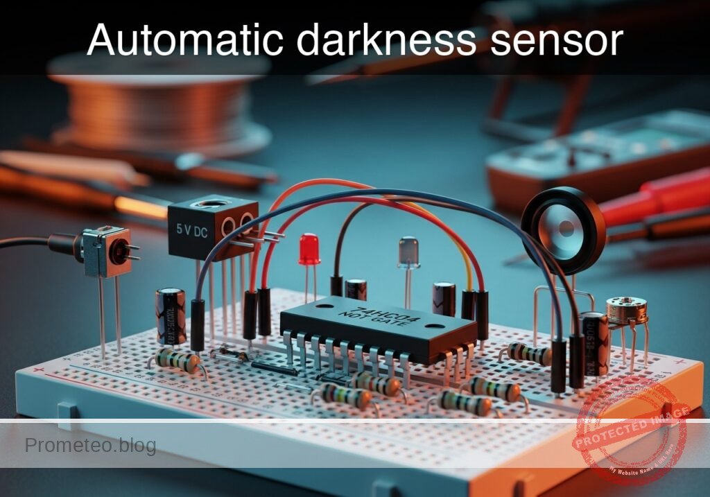
Level: Basic — Use a 74HC04 inverter and an LDR to automatically switch on an LED when ambient light drops.
Objective and use case
You will build an automatic light control circuit that detects darkness using a Light Dependent Resistor (LDR) and activates an LED using a 74HC04 digital inverter.
- Why it is useful:
- Automating streetlights to turn on only at night to save energy.
- Activating emergency pathway lighting during power failures or darkness.
- Controlling garden solar lights automatically.
- Adjusting screen brightness on mobile devices based on ambient light.
- Expected outcome:
- When the LDR is exposed to bright light, the LED remains OFF.
- When the LDR is covered (darkness), the LED turns ON.
- The voltage at the logic gate input transitions from Logic High (5V) to Logic Low (0V) as it gets darker.
- Target audience and level: Students and hobbyists familiar with basic breadboarding.
Materials
- V1: 5 V DC supply, function: Main power source.
- R1: LDR (GL5528 or similar), function: Light sensor (Variable resistor).
- R2: 10 kΩ potentiometer, function: Sensitivity calibration (Pull-down).
- U1: 74HC04, function: Hex Inverter (NOT gate).
- R3: 330 Ω resistor, function: LED current limiting.
- D1: Red LED, function: Visual output indicator.
Pin-out of the IC used
Chip: 74HC04 (Hex Inverter)
| Pin | Name | Logic function | Connection in this case |
|---|---|---|---|
| 14 | VCC | Power (+) | Connect to VCC (5V) |
| 7 | GND | Ground (-) | Connect to 0 (GND) |
| 1 | 1A | Input | Connect to sensor node VSENSE |
| 2 | 1Y | Output | Connect to LED node VOUT |
(Note: Pins 3, 5, 9, 11, 13 are unused inputs and should ideally be connected to GND in permanent circuits to prevent noise, though not strictly required for this quick test.)
Wiring guide
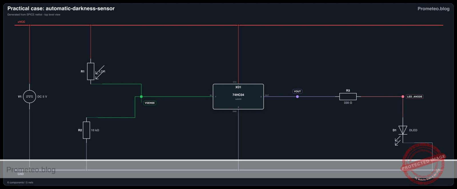
Use the following explicit node connections to build the circuit on your breadboard:
- Power Supply:
- V1 positive terminal connects to node VCC.
- V1 negative terminal connects to node 0 (GND).
- Sensor Stage (Voltage Divider):
- R1 (LDR) connects between VCC and node VSENSE.
- R2 (Potentiometer) connects between node VSENSE and 0 (GND).
- Note: Adjust R2 so the voltage at VSENSE varies when light changes.
- Logic Stage (Inverter):
- U1 Pin 14 connects to VCC.
- U1 Pin 7 connects to 0.
- U1 Pin 1 (Input) connects to node VSENSE.
- U1 Pin 2 (Output) connects to node VOUT.
- Output Stage:
- R3 connects between node VOUT and node LED_ANODE.
- D1 connects between node LED_ANODE (Anode/Long leg) and 0 (Cathode/Short leg).
Conceptual block diagram
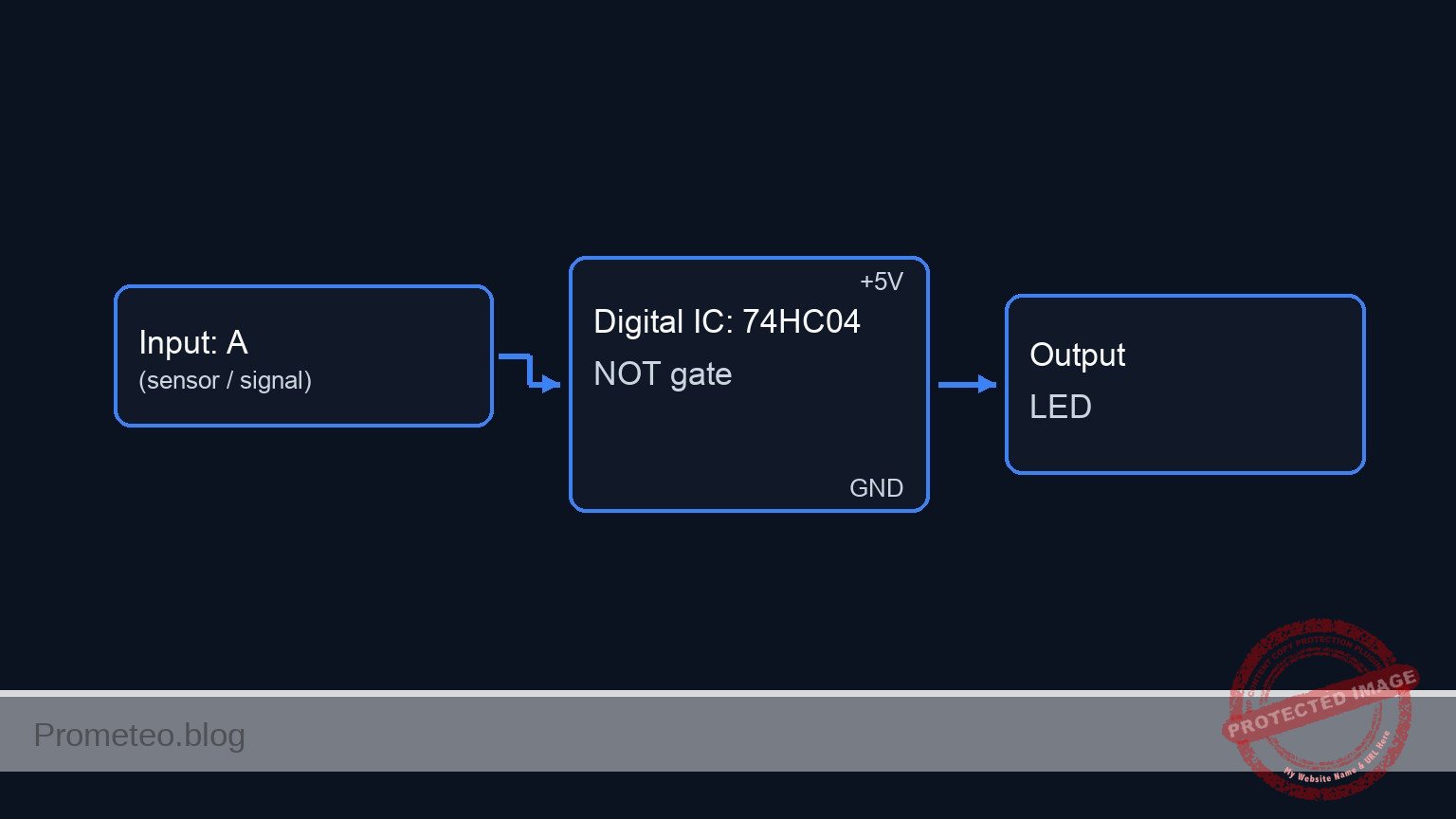
Schematic
[ INPUT / SENSOR STAGE ]               [ LOGIC STAGE ]                  [ OUTPUT STAGE ]

 [ VCC ] --> [ R1: LDR (Sensor) ] --+
                                    |
                                    v
                               [ VSENSE ] --(Pin 1)--> [ U1: 74HC04 ] --(Pin 2)--> [ R3: 330 Ohm ] --> [ D1: LED ] --> GND
                                    ^                  [  NOT Gate  ]
                                    |
 [ GND ] --> [ R2: Pot (Calib) ] ---+
Electrical diagram
Truth table
The 74HC04 inverts the input signal. We configure the sensors so that «Bright» creates a HIGH input.
| Ambient Condition | LDR Resistance | Voltage at VSENSE (Input) | Logic Input | Logic Output (VOUT) | LED State |
|---|---|---|---|---|---|
| Bright | Low | High (> 2.5V) | 1 | 0 (GND) | OFF |
| Dark | High | Low (< 1.5V) | 0 | 1 (5V) | ON |
Measurements and tests
- Calibration: Expose the LDR to normal room light. Adjust potentiometer R2 until the LED turns OFF.
- Voltage Check (Bright): Measure voltage between VSENSE and GND. It should be close to 5V (Logic 1). The output at VOUT should be near 0V.
- Activation: Cover the LDR with your hand to simulate darkness.
- Voltage Check (Dark): Measure VSENSE again. It should drop towards 0V (Logic 0). The output VOUT should jump to approx. 5V, turning the LED ON.
SPICE netlist and simulation
Reference SPICE Netlist (ngspice) — excerptFull SPICE netlist (ngspice)
* Practical case: Automatic darkness sensor

* --- Models ---
* Generic Red LED Model
.model DLED D (IS=1e-22 N=1.5 RS=5 BV=5 IBV=10u CJO=10p)

* --- Subcircuits ---
* 74HC04 Hex Inverter Model (Behavioral)
* Pins: 1=Input, 2=Output, 7=GND, 14=VCC
* Maps to subckt args: In Out GND VCC
.subckt 74HC04 In Out GND VCC
  * Robust Sigmoid Transfer Function for Inverter
  * Threshold is VCC/2. Output swings between GND and VCC.
  * Formula: Vout = VCC * (1 / (1 + exp(50 * (V(In) - V(VCC)/2))))
  B_INV Out GND V = V(VCC) * (1 / (1 + exp(50 * (V(In) - V(VCC)/2))))
.ends

* --- Main Circuit Components ---

* 1. Power Supply
* ... (truncated in public view) ...
Copy this content into a .cir file and run with ngspice.
* Practical case: Automatic darkness sensor

* --- Models ---
* Generic Red LED Model
.model DLED D (IS=1e-22 N=1.5 RS=5 BV=5 IBV=10u CJO=10p)

* --- Subcircuits ---
* 74HC04 Hex Inverter Model (Behavioral)
* Pins: 1=Input, 2=Output, 7=GND, 14=VCC
* Maps to subckt args: In Out GND VCC
.subckt 74HC04 In Out GND VCC
  * Robust Sigmoid Transfer Function for Inverter
  * Threshold is VCC/2. Output swings between GND and VCC.
  * Formula: Vout = VCC * (1 / (1 + exp(50 * (V(In) - V(VCC)/2))))
  B_INV Out GND V = V(VCC) * (1 / (1 + exp(50 * (V(In) - V(VCC)/2))))
.ends

* --- Main Circuit Components ---

* 1. Power Supply
* V1: 5V DC supply
V1 VCC 0 DC 5

* 2. Sensor Stage (Voltage Divider)
* R1: LDR (Light Dependent Resistor)
* Implementation: A dummy R1 is placed to satisfy the BOM.
* A parallel behavioral source (B_LDR) implements the dynamic resistance change.
R1 VCC VSENSE 100Meg
B_LDR VCC VSENSE I = V(VCC, VSENSE) / V(RES_CTRL)

* R2: 10k Potentiometer (Sensitivity Calibration)
R2 VSENSE 0 10k

* Dynamic Stimulus for LDR (Simulates Light Conditions)
* Generates a control voltage representing Ohms.
* Pulse sweeps from 1k (Light) to 100k (Dark).
* Logic: Light(1k) -> VSENSE High -> LED OFF. Dark(100k) -> VSENSE Low -> LED ON.
V_LDR_CTRL RES_CTRL 0 PULSE(1k 100k 0 200u 200u 400u 2ms)

* 3. Logic Stage
* U1: 74HC04 Hex Inverter
* Connections: Pin 1 (In)=VSENSE, Pin 2 (Out)=VOUT, Pin 7=0, Pin 14=VCC
XU1 VSENSE VOUT 0 VCC 74HC04

* 4. Output Stage
* R3: LED Current Limiting Resistor (330 Ohm)
R3 VOUT LED_ANODE 330

* D1: Red LED
D1 LED_ANODE 0 DLED

* --- Analysis Directives ---
* Transient analysis to capture the Light/Dark transition
.tran 10u 2ms

* Print specific node voltages for validation
.print tran V(VSENSE) V(VOUT) V(LED_ANODE)

* Compute DC operating point
.op

.end
Simulation Results (Transient Analysis)

Show raw data table (224 rows)
Index   time            v(vsense)       v(vout)         v(led_anode)
0	0.000000e+00	4.545459e+00	1.916016e-44	6.555013e-37
1	1.000000e-07	4.525005e+00	3.875543e-44	2.124754e-38
2	2.000000e-07	4.504821e+00	1.070470e-43	-1.98700e-38
3	4.000000e-07	4.464726e+00	4.391831e-43	-3.30922e-39
4	8.000000e-07	4.386087e+00	5.351931e-42	4.963938e-40
5	1.600000e-06	4.240174e+00	7.789996e-38	7.726704e-38
6	3.200000e-06	3.973321e+00	1.292803e-32	1.287493e-32
7	6.400000e-06	3.529123e+00	-6.61237e-21	-6.59876e-21
8	1.280000e-05	2.884261e+00	2.263832e-08	2.262430e-08
9	1.905731e-05	2.447108e+00	4.668386e+00	1.823995e+00
10	2.344117e-05	2.212214e+00	4.999997e+00	1.833723e+00
11	2.751655e-05	2.030989e+00	5.000000e+00	1.833029e+00
12	3.266976e-05	1.840361e+00	5.000000e+00	1.833116e+00
13	4.266976e-05	1.556825e+00	5.000000e+00	1.833028e+00
14	5.266976e-05	1.349010e+00	5.000000e+00	1.833116e+00
15	6.266976e-05	1.190157e+00	5.000000e+00	1.833028e+00
16	7.266976e-05	1.064784e+00	5.000000e+00	1.833116e+00
17	8.266976e-05	9.633175e-01	5.000000e+00	1.833028e+00
18	9.266976e-05	8.795141e-01	5.000000e+00	1.833116e+00
19	1.026698e-04	8.091310e-01	5.000000e+00	1.833028e+00
20	1.126698e-04	7.491835e-01	5.000000e+00	1.833116e+00
21	1.226698e-04	6.975110e-01	5.000000e+00	1.833028e+00
22	1.326698e-04	6.525106e-01	5.000000e+00	1.833116e+00
23	1.426698e-04	6.129684e-01	5.000000e+00	1.833028e+00
... (200 more rows) ...
Reference SPICE netlist (ngspice)
* Practical case: Automatic darkness sensor

* --- Models ---
* Generic Red LED Model
.model DLED D (IS=1e-22 N=1.5 RS=5 BV=5 IBV=10u CJO=10p)

* --- Subcircuits ---
* 74HC04 Hex Inverter Model (Behavioral)
* Pins: 1=Input, 2=Output, 7=GND, 14=VCC
* Maps to subckt args: In Out GND VCC
.subckt 74HC04 In Out GND VCC
  * Robust Sigmoid Transfer Function for Inverter
  * Threshold is VCC/2. Output swings between GND and VCC.
  * Formula: Vout = VCC * (1 / (1 + exp(50 * (V(In) - V(VCC)/2))))
  B_INV Out GND V = V(VCC) * (1 / (1 + exp(50 * (V(In) - V(VCC)/2))))
.ends

* --- Main Circuit Components ---

* 1. Power Supply
* V1: 5V DC supply
V1 VCC 0 DC 5

* 2. Sensor Stage (Voltage Divider)
* R1: LDR (Light Dependent Resistor)
* Implementation: A dummy R1 is placed to satisfy the BOM.
* A parallel behavioral source (B_LDR) implements the dynamic resistance change.
R1 VCC VSENSE 100Meg
B_LDR VCC VSENSE I = V(VCC, VSENSE) / V(RES_CTRL)

* R2: 10k Potentiometer (Sensitivity Calibration)
R2 VSENSE 0 10k

* Dynamic Stimulus for LDR (Simulates Light Conditions)
* Generates a control voltage representing Ohms.
* Pulse sweeps from 1k (Light) to 100k (Dark).
* Logic: Light(1k) -> VSENSE High -> LED OFF. Dark(100k) -> VSENSE Low -> LED ON.
V_LDR_CTRL RES_CTRL 0 PULSE(1k 100k 0 200u 200u 400u 2ms)

* 3. Logic Stage
* U1: 74HC04 Hex Inverter
* Connections: Pin 1 (In)=VSENSE, Pin 2 (Out)=VOUT, Pin 7=0, Pin 14=VCC
XU1 VSENSE VOUT 0 VCC 74HC04

* 4. Output Stage
* R3: LED Current Limiting Resistor (330 Ohm)
R3 VOUT LED_ANODE 330

* D1: Red LED
D1 LED_ANODE 0 DLED

* --- Analysis Directives ---
* Transient analysis to capture the Light/Dark transition
.tran 10u 2ms

* Print specific node voltages for validation
.print tran V(VSENSE) V(VOUT) V(LED_ANODE)

* Compute DC operating point
.op

.end
Simulation Results (Transient Analysis)
Common mistakes and how to avoid them
- Swapping LDR and Potentiometer: If you swap R1 and R2, the logic inverts: the light will turn ON when it is bright and OFF when it is dark. Ensure the LDR is connected to VCC and the Potentiometer to GND.
- LED inserted backwards: If D1 does not light up when VOUT is high, check the polarity. The longer leg (anode) must face the resistor R3.
- Sensitivity too low: If the LED never turns off, R2 might be set to too high a resistance, keeping voltage at VSENSE always high. Turn the knob to lower the resistance.
Troubleshooting
- LED is always ON:
- Cause: Potentiometer resistance is too high or LDR is broken (open circuit).
- Fix: Decrease R2 value by turning the knob. Check LDR connections.
- LED is always OFF:
- Cause: Potentiometer resistance is too low (shorting input to ground) or U1 is not powered.
- Fix: Verify Pin 14 has 5V. Increase R2 resistance slightly.
- LED flickers:
- Cause: The light level is right at the switching threshold of the 74HC04.
- Fix: Adjust R2 slightly to move away from the threshold or shade the LDR more decisively.
Possible improvements and extensions
- Add Hysteresis: Replace the 74HC04 with a 74HC14 (Schmidt Trigger Inverter). This prevents flickering when the light transitions slowly (dusk/dawn).
- High Power Load: Connect the output pin to a transistor (like a 2N2222) and a relay module to switch a 110V/220V desk lamp instead of a small LED.
More Practical Cases on Prometeo.blog
Find this product and/or books on this topic on Amazon
As an Amazon Associate, I earn from qualifying purchases. If you buy through this link, you help keep this project running.
Quick Quiz

Telecommunications Electronics Engineer and Computer Engineer (official degrees in Spain).