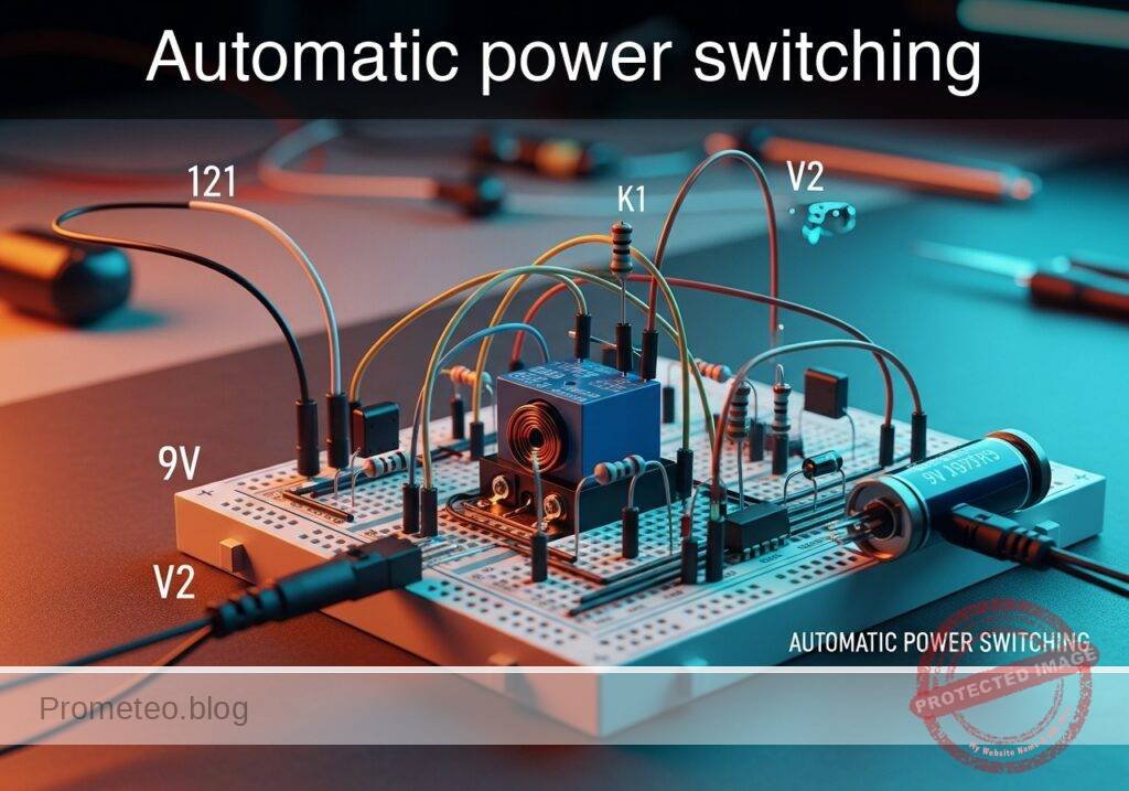
Level: Medium – Implement an SPDT relay to automatically alternate between a main power supply and a backup battery.
Objective and use case
In this practical case, you will build a power management circuit using a Single Pole Double Throw (SPDT) relay. The circuit will automatically switch a connected load to a backup battery whenever the main power supply fails.
This automated switching topology is highly useful in several real-world applications:
* Uninterruptible Power Supplies (UPS) for routers and critical network equipment.
* Alarm and security systems that require continuous operation during grid power outages.
* Medical monitoring devices that must remain functional during patient transport.
* Solar power systems that automatically switch to battery power after sunset.
Expected outcome:
* When the main supply (V_MAIN) is active, the relay coil energizes, and the load connects to the Normally Open (NO) contact powered by the main supply.
* When the main supply fails (drops to 0 V), the relay de-energizes, seamlessly transferring the load to the Normally Closed (NC) contact powered by the backup battery.
* The load voltage (V_LOAD_OUT) remains continuous, save for a minor mechanical switching delay.
* A visual LED indicator successfully reports the presence of the main power supply.
Target audience: Hobbyists and intermediate electronics students learning about electromechanical relays and power redundancy.
Materials
- V1: 12 V DC supply, function: main power source
- V2: 9 V DC supply, function: backup battery source
- K1: 12 V SPDT relay, function: automatic power switch
- D1: 1N4007 diode, function: flyback diode to protect against relay coil voltage spikes
- D2: Red LED, function: main power indicator
- R1: 1 kΩ resistor, function: LED current limiting
- R2: 100 Ω resistor, function: simulated system load
Wiring guide
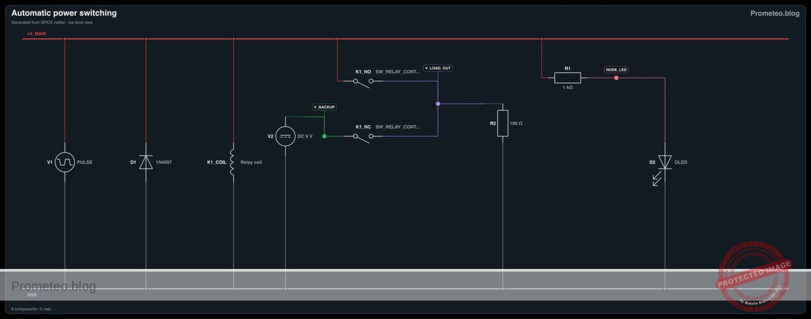
- V1: Connect positive terminal to V_MAIN and negative terminal to 0 (GND).
- V2: Connect positive terminal to V_BACKUP and negative terminal to 0 (GND).
- K1 (Coil): Connect one side to V_MAIN and the other side to 0 (GND).
- D1: Connect parallel to the K1 coil. Connect the cathode to V_MAIN and the anode to 0 (GND).
- K1 (NO Contact): Connect the Normally Open terminal to V_MAIN.
- K1 (NC Contact): Connect the Normally Closed terminal to V_BACKUP.
- K1 (COM Contact): Connect the Common terminal to V_LOAD_OUT.
- R2: Connect between V_LOAD_OUT and 0 (GND).
- R1: Connect between V_MAIN and NODE_LED.
- D2: Connect the anode to NODE_LED and the cathode to 0 (GND).
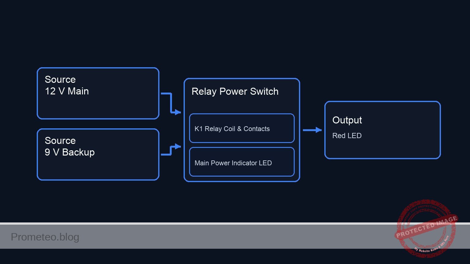
Conceptual block diagram
Schematic
[ V1: 12 V Main ] --(V_MAIN)--> [ K1 Coil || D1 (Rev) ] --> GND
                                       |
                                 (Magnetic Link)
                                       v
[ V1: 12 V Main ] --(V_MAIN)--> [ K1: NO Contact ] --+
                                                    |
                                                  (COM)--> [ V_LOAD_OUT ] --> [ R2: 100 Ω Load ] --> GND
                                                    |
[ V2: 9 V Backup ] -(V_BACKUP)-> [ K1: NC Contact ] -+

[ V1: 12 V Main ] --(V_MAIN)--> [ R1: 1 kΩ ] --(NODE_LED)--> [ D2: Red LED ] --> GND
Electrical diagram
Measurements and tests
- Connect and activate both V1 (12 V) and V2 (9 V).
- Measure the voltage at V_MAIN and V_BACKUP with a multimeter to verify both sources are stable.
- Measure the voltage at V_LOAD_OUT. It should read approximately 12 V. The relay should emit an audible «click» upon power-up, and the indicator LED (D2) should be brightly lit.
- Disconnect V1 to simulate a power outage (V_MAIN drops to 0 V).
- Measure the voltage at V_LOAD_OUT again. It should now read approximately 9 V, confirming the load has successfully transferred to the backup battery. The LED should turn off.
- Reconnect V1. Observe the relay clicking again as V_LOAD_OUT returns to 12 V.
SPICE netlist and simulation
Reference SPICE Netlist (ngspice) — excerptFull SPICE netlist (ngspice)
* Automatic power switching
.width out=256

* Power Sources
V1 V_MAIN 0 PULSE(12 0 200u 1u 1u 200u 500u)
V2 V_BACKUP 0 DC 9

* K1 Relay Coil (modeled as series inductor and resistor)
L_K1 V_MAIN K1_COIL_INT 1m
R_K1 K1_COIL_INT 0 400

* K1 Relay Contacts (modeled as voltage-controlled switches)
* Normally Open (NO) contact between V_MAIN and V_LOAD_OUT, controlled by V_MAIN
S_K1_NO V_MAIN V_LOAD_OUT V_MAIN 0 Relay_NO
* Normally Closed (NC) contact between V_BACKUP and V_LOAD_OUT, controlled by inverted V_MAIN
S_K1_NC V_BACKUP V_LOAD_OUT 0 V_MAIN Relay_NC

* D1 Flyback Diode (Anode to 0, Cathode to V_MAIN)
D1 0 V_MAIN 1N4007

* ... (truncated in public view) ...
Copy this content into a .cir file and run with ngspice.
* Automatic power switching
.width out=256

* Power Sources
V1 V_MAIN 0 PULSE(12 0 200u 1u 1u 200u 500u)
V2 V_BACKUP 0 DC 9

* K1 Relay Coil (modeled as series inductor and resistor)
L_K1 V_MAIN K1_COIL_INT 1m
R_K1 K1_COIL_INT 0 400

* K1 Relay Contacts (modeled as voltage-controlled switches)
* Normally Open (NO) contact between V_MAIN and V_LOAD_OUT, controlled by V_MAIN
S_K1_NO V_MAIN V_LOAD_OUT V_MAIN 0 Relay_NO
* Normally Closed (NC) contact between V_BACKUP and V_LOAD_OUT, controlled by inverted V_MAIN
S_K1_NC V_BACKUP V_LOAD_OUT 0 V_MAIN Relay_NC

* D1 Flyback Diode (Anode to 0, Cathode to V_MAIN)
D1 0 V_MAIN 1N4007

* Main Power Indicator
R1 V_MAIN NODE_LED 1k
D2 NODE_LED 0 DLED

* Simulated System Load
R2 V_LOAD_OUT 0 100

* Component Models
.model 1N4007 D(IS=7.02767n RS=0.0341512 N=1.80803 EG=1.05743 XTI=5 BV=1000 IBV=5e-08 CJO=1e-11 VJ=0.7 M=0.5 FC=0.5 TT=1e-07)
.model DLED D(IS=1e-15 RS=10 N=2.0)
.model Relay_NO SW(vt=6 vh=0.5 ron=0.05 roff=10Meg)
.model Relay_NC SW(vt=-6 vh=0.5 ron=0.05 roff=10Meg)

* Analysis Directives
.op
.tran 1u 500u
.print tran V(V_MAIN) V(V_LOAD_OUT) V(V_BACKUP) V(NODE_LED) I(L_K1)

.end
Simulation Results (Transient Analysis)

Show raw data table (557 rows)
Index   time            v(v_main)       v(v_load_out)   v(v_backup)     v(node_led)     l_k1#branch
0	0.000000e+00	1.200000e+01	1.199400e+01	9.000000e+00	1.653685e+00	3.000000e-02
1	1.000000e-08	1.200000e+01	1.199400e+01	9.000000e+00	1.653685e+00	3.000000e-02
2	2.000000e-08	1.200000e+01	1.199400e+01	9.000000e+00	1.653685e+00	3.000000e-02
3	4.000000e-08	1.200000e+01	1.199400e+01	9.000000e+00	1.653685e+00	3.000000e-02
4	8.000000e-08	1.200000e+01	1.199400e+01	9.000000e+00	1.653685e+00	3.000000e-02
5	1.600000e-07	1.200000e+01	1.199400e+01	9.000000e+00	1.653685e+00	3.000000e-02
6	3.200000e-07	1.200000e+01	1.199400e+01	9.000000e+00	1.653685e+00	3.000000e-02
7	6.400000e-07	1.200000e+01	1.199400e+01	9.000000e+00	1.653685e+00	3.000000e-02
8	1.280000e-06	1.200000e+01	1.199400e+01	9.000000e+00	1.653685e+00	3.000000e-02
9	2.280000e-06	1.200000e+01	1.199400e+01	9.000000e+00	1.653685e+00	3.000000e-02
10	3.280000e-06	1.200000e+01	1.199400e+01	9.000000e+00	1.653685e+00	3.000000e-02
11	4.280000e-06	1.200000e+01	1.199400e+01	9.000000e+00	1.653685e+00	3.000000e-02
12	5.280000e-06	1.200000e+01	1.199400e+01	9.000000e+00	1.653685e+00	3.000000e-02
13	6.280000e-06	1.200000e+01	1.199400e+01	9.000000e+00	1.653685e+00	3.000000e-02
14	7.280000e-06	1.200000e+01	1.199400e+01	9.000000e+00	1.653685e+00	3.000000e-02
15	8.280000e-06	1.200000e+01	1.199400e+01	9.000000e+00	1.653685e+00	3.000000e-02
16	9.280000e-06	1.200000e+01	1.199400e+01	9.000000e+00	1.653685e+00	3.000000e-02
17	1.028000e-05	1.200000e+01	1.199400e+01	9.000000e+00	1.653685e+00	3.000000e-02
18	1.128000e-05	1.200000e+01	1.199400e+01	9.000000e+00	1.653685e+00	3.000000e-02
19	1.228000e-05	1.200000e+01	1.199400e+01	9.000000e+00	1.653685e+00	3.000000e-02
20	1.328000e-05	1.200000e+01	1.199400e+01	9.000000e+00	1.653685e+00	3.000000e-02
21	1.428000e-05	1.200000e+01	1.199400e+01	9.000000e+00	1.653685e+00	3.000000e-02
22	1.528000e-05	1.200000e+01	1.199400e+01	9.000000e+00	1.653685e+00	3.000000e-02
23	1.628000e-05	1.200000e+01	1.199400e+01	9.000000e+00	1.653685e+00	3.000000e-02
... (533 more rows) ...
Reference SPICE netlist (ngspice)
* Automatic power switching
.width out=256

* Power Sources
V1 V_MAIN 0 PULSE(12 0 200u 1u 1u 200u 500u)
V2 V_BACKUP 0 DC 9

* K1 Relay Coil (modeled as series inductor and resistor)
L_K1 V_MAIN K1_COIL_INT 1m
R_K1 K1_COIL_INT 0 400

* K1 Relay Contacts (modeled as voltage-controlled switches)
* Normally Open (NO) contact between V_MAIN and V_LOAD_OUT, controlled by V_MAIN
S_K1_NO V_MAIN V_LOAD_OUT V_MAIN 0 Relay_NO
* Normally Closed (NC) contact between V_BACKUP and V_LOAD_OUT, controlled by inverted V_MAIN
S_K1_NC V_BACKUP V_LOAD_OUT 0 V_MAIN Relay_NC

* D1 Flyback Diode (Anode to 0, Cathode to V_MAIN)
D1 0 V_MAIN 1N4007

* Main Power Indicator
R1 V_MAIN NODE_LED 1k
D2 NODE_LED 0 DLED

* Simulated System Load
R2 V_LOAD_OUT 0 100

* Component Models
.model 1N4007 D(IS=7.02767n RS=0.0341512 N=1.80803 EG=1.05743 XTI=5 BV=1000 IBV=5e-08 CJO=1e-11 VJ=0.7 M=0.5 FC=0.5 TT=1e-07)
.model DLED D(IS=1e-15 RS=10 N=2.0)
.model Relay_NO SW(vt=6 vh=0.5 ron=0.05 roff=10Meg)
.model Relay_NC SW(vt=-6 vh=0.5 ron=0.05 roff=10Meg)

* Analysis Directives
.op
.tran 1u 500u
.print tran V(V_MAIN) V(V_LOAD_OUT) V(V_BACKUP) V(NODE_LED) I(L_K1)

.end
Simulation Results (Transient Analysis)
Common mistakes and how to avoid them
- Relay coil voltage mismatch: Using a 5 V relay on a 12 V line will cause the coil to overheat and fail quickly. Always ensure the relay’s rated coil voltage matches the main supply voltage exactly.
- Omitting the flyback diode: Failing to install the reverse-biased diode across the relay coil can result in high-voltage spikes when the main power is abruptly disconnected, potentially damaging parallel components on the main power bus.
- Reversing NO and NC contacts: Wiring the backup battery to the NO contact and the main supply to the NC contact will result in a dead system when the main power fails. Verify the relay pinout before soldering or powering the circuit.
Troubleshooting
- Symptom: The load completely loses power when the main supply drops.
- Cause: The backup battery is either dead or connected to the Normally Open (NO) terminal instead of the Normally Closed (NC) terminal.
- Fix: Measure the battery voltage independently, then verify its connection to the NC terminal of the relay.
- Symptom: The relay chatters or buzzes continuously instead of switching cleanly.
- Cause: The main power supply cannot provide enough current for both the relay coil and the load, causing the voltage to repeatedly dip below the relay’s hold threshold.
- Fix: Upgrade the main power supply to a higher current rating, or add a large smoothing capacitor across the V_MAIN line.
- Symptom: The indicator LED does not light up, but the switching works.
- Cause: The LED is inserted with reverse polarity, or the current limiting resistor is disconnected.
- Fix: Verify that the flat side (cathode) of the LED is connected to ground.
Possible improvements and extensions
- Add a large electrolytic capacitor (e.g., 1000 µF) in parallel with the load (R2) to smooth out the brief power interruption (brownout) caused by the mechanical switching time of the relay contacts.
- Replace the mechanical relay with a solid-state diode OR-ing circuit (using Schottky diodes) for completely seamless, zero-delay switching without any moving parts.
More Practical Cases on Prometeo.blog
Find this product and/or books on this topic on Amazon
As an Amazon Associate, I earn from qualifying purchases. If you buy through this link, you help keep this project running.
Quick Quiz

Telecommunications Electronics Engineer and Computer Engineer (official degrees in Spain).