
Level: Medium – Disconnect a critical load using a normally closed relay contact when a voltage threshold is exceeded.
Objective and use case
In this practical case, you will build a hardware-based overvoltage protection circuit. It uses a Zener diode to set a voltage threshold and a bipolar junction transistor (BJT) to actuate an electromechanical relay, mechanically disconnecting power when the voltage spikes to dangerous levels.
This topology is highly useful in real-world scenarios:
– Safeguarding sensitive 5 V microcontrollers from accidental power supply surges.
– Protecting expensive sensors or instruments in automotive environments where alternator spikes occur.
– Ensuring battery-powered or USB-powered devices mechanically cut out during a charger regulator failure.
Expected outcome:
– When the input voltage (v-in) is in the safe range (e.g., 5.0 V), the BJT remains off, the relay is unpowered, and the normally closed (NC) contact feeds power to the load.
– When v-in exceeds the Zener threshold plus the BJT base-emitter drop (around 6.3 V), the Zener conducts.
– Base current flows, the BJT switch turns on, and the relay coil energizes.
– The relay’s NC contact opens, triggering a v-load-disconnect event that drops the load voltage to 0 V.
– Target audience and level: Intermediate electronics students exploring analog voltage thresholds and electromechanical switching.
Materials
- V1: Variable DC supply (0-9 V), function: provides system input voltage (v-in)
- D1: 5.6 V Zener diode (e.g., 1N4734 A), function: sets the overvoltage threshold reference
- R1: 1 kΩ resistor, function: base current limiting for the BJT
- R2: 10 kΩ resistor, function: base pull-down to ensure the BJT turns off cleanly
- Q1: 2N3904 NPN transistor, function: relay driver switch
- D2: 1N4148 or 1N4007 diode, function: flyback protection for the relay coil
- K1: 5 V SPDT Relay, function: disconnects the load using its normally closed (NC) contact
- R_LOAD: 100 Ω resistor, function: simulated critical load
Wiring guide
- V1: positive terminal connects to node V_IN, negative terminal connects to node 0 (GND).
- D1: cathode connects to node V_IN, anode connects to node V_ZENER.
- R1: connects between node V_ZENER and node BASE.
- R2: connects between node BASE and node 0.
- Q1: collector connects to node COLLECTOR, base connects to node BASE, emitter connects to node 0.
- K1_COIL: the relay coil connects between node V_IN and node COLLECTOR.
- D2: cathode connects to node V_IN, anode connects to node COLLECTOR (wired anti-parallel to the relay coil).
- K1_COM: the relay’s common contact connects to node V_IN.
- K1_NC: the relay’s normally closed contact connects to node LOAD_PWR.
- R_LOAD: connects between node LOAD_PWR and node 0.
Conceptual block diagram
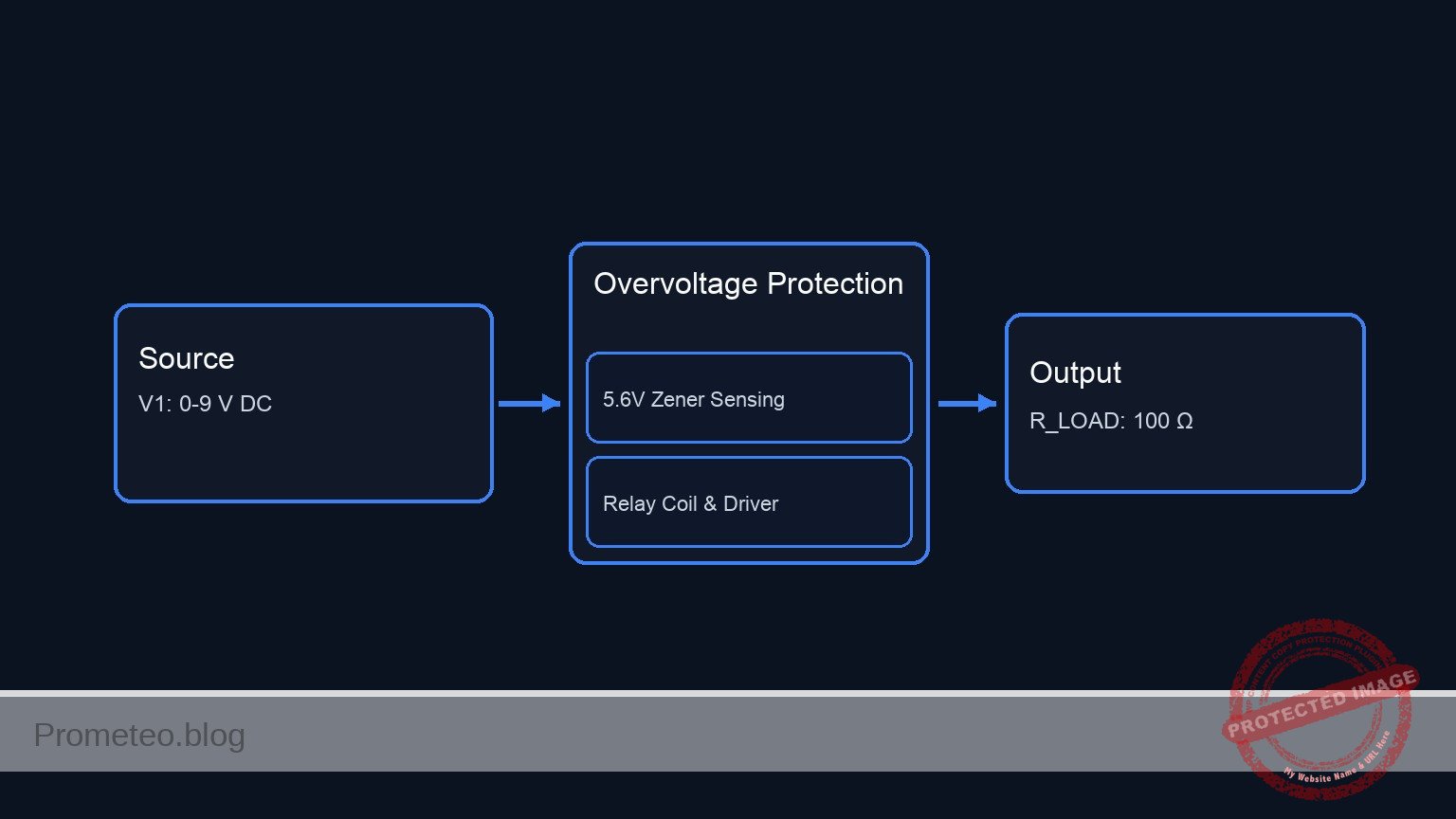
Schematic
POWER SOURCE:
[ V1: 0-9 V DC ] --(V_IN)--> System Power
[ V1: Negative ] ---------> GND

1. OVERVOLTAGE SENSING & CONTROL PATH:
V_IN --> [ D1: 5.6 V Zener ] --(V_ZENER)--> [ R1: 1 kΩ ] --(BASE)--> [ Q1:Base ]
                                                             |
                                                        [ R2: 10 kΩ ]
                                                             |
                                                            GND

2. RELAY COIL & DRIVER PATH:
V_IN --> [ K1_COIL || D2: Flyback(Rev) ] --(COLLECTOR)--> [ Q1:Collector ]
                       |                                        |
                (Magnetic Link)                            [ Q1:Emitter ]
                       |                                        |
                       v                                       GND

3. PROTECTED LOAD PATH:
V_IN --> [ K1_COM ] --(Normally Closed)--> [ K1_NC ] --(LOAD_PWR)--> [ R_LOAD: 100 Ω ] --> GND
Electrical diagram
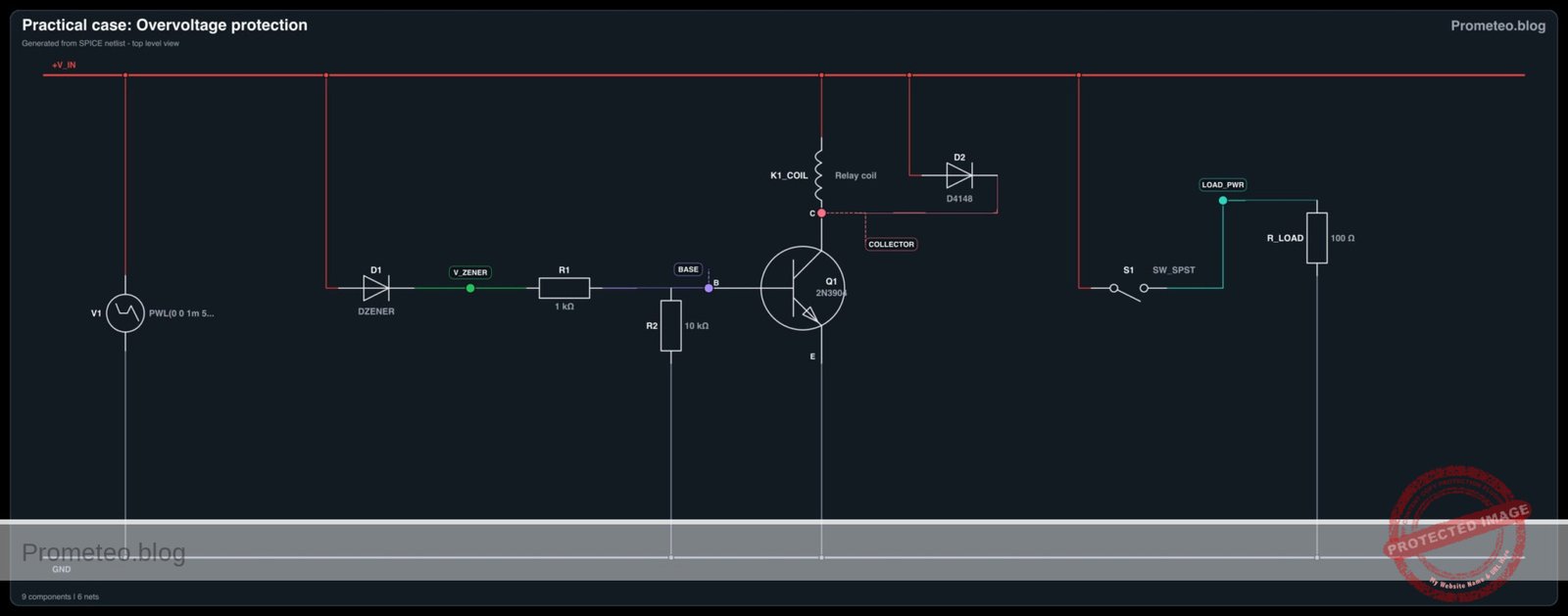
Measurements and tests
- Set the variable power supply V1 to exactly 5.0 V.
- Measure v-in relative to ground. Verify it is 5.0 V.
- Measure the voltage across the load (LOAD_PWR to 0). It should read 5.0 V, indicating the relay is deactivated and the NC contact is closed.
- Slowly increase the voltage of V1. Monitor v-zener (the voltage at the anode of D1). It will remain near 0 V until v-in crosses the ~5.6 V breakdown threshold of the Zener diode.
- Push V1 up to 6.5 V. Observe that v-zener rises, pushing current into the base of Q1.
- Verify the v-load-disconnect event: listen for the relay click. Measure the voltage at LOAD_PWR; it should instantly drop to 0 V as the NC contact opens, successfully protecting the load.
SPICE netlist and simulation
Reference SPICE Netlist (ngspice) — excerptFull SPICE netlist (ngspice)
* Practical case: Overvoltage protection
.width out=256

* Input Voltage Source (Sweeps from 0V to normal 5V, then overvoltage 9V, then back)
V1 V_IN 0 PWL(0 0 1m 5 4m 5 5m 9 6m 9 7m 5 9m 5 10m 0)

* Zener Diode for threshold detection
D1 V_IN V_ZENER DZENER

* Base resistors for Q1
R1 V_ZENER BASE 1k
R2 BASE 0 10k

* Relay Driver Transistor
Q1 COLLECTOR BASE 0 2N3904

* Relay Coil (Modeled as series inductor and resistor)
L_K1_COIL V_IN K1_COIL_INT 10m
R_K1_COIL K1_COIL_INT COLLECTOR 100

* ... (truncated in public view) ...
Copy this content into a .cir file and run with ngspice.
* Practical case: Overvoltage protection
.width out=256

* Input Voltage Source (Sweeps from 0V to normal 5V, then overvoltage 9V, then back)
V1 V_IN 0 PWL(0 0 1m 5 4m 5 5m 9 6m 9 7m 5 9m 5 10m 0)

* Zener Diode for threshold detection
D1 V_IN V_ZENER DZENER

* Base resistors for Q1
R1 V_ZENER BASE 1k
R2 BASE 0 10k

* Relay Driver Transistor
Q1 COLLECTOR BASE 0 2N3904

* Relay Coil (Modeled as series inductor and resistor)
L_K1_COIL V_IN K1_COIL_INT 10m
R_K1_COIL K1_COIL_INT COLLECTOR 100

* Flyback Diode
D2 V_IN COLLECTOR D4148

* Relay Normally Closed (NC) Contact
* Modeled as a voltage-controlled switch controlled by the coil voltage (V_IN - COLLECTOR)
* When Q1 is OFF, coil voltage is 0V -> Switch is CLOSED (roff = 0.1)
* When Q1 is ON, coil voltage is > 6V -> Switch is OPEN (ron = 100meg)
S1 V_IN LOAD_PWR V_IN COLLECTOR RelayNC

* Critical Load
R_LOAD LOAD_PWR 0 100

* Models
.model DZENER D(IS=1e-15 RS=10 N=1 BV=5.6 IBV=5m)
.model D4148 D(IS=1e-14 RS=0.1 N=1)
.model 2N3904 NPN(IS=1E-14 VAF=100 BF=300 IKF=0.4 XTB=1.5 BR=4 CJC=4E-12 CJE=8E-12 RB=20 RC=0.1 RE=0.1 TR=250E-9 TF=350E-12 ITF=1 VTF=2 XTF=3)
.model RelayNC SW(vt=3 vh=0.5 ron=100meg roff=0.1)

* Simulation Directives
.print tran V(V_IN) V(LOAD_PWR) V(BASE) V(COLLECTOR) V(V_ZENER) I(L_K1_COIL)
.tran 10u 10m
.op
.end
Simulation Results (Transient Analysis)

Show raw data table (1788 rows)
Index   time            v(v_in)         v(load_pwr)     v(base)         v(collector)    v(v_zener)      l_k1_coil#branc
0	0.000000e+00	0.000000e+00	0.000000e+00	4.369907e-29	1.104363e-28	4.276684e-29	-1.10436e-30
1	1.000000e-07	5.000000e-04	4.995005e-04	2.124049e-05	1.169502e-04	2.124049e-05	3.826672e-09
2	1.128896e-07	5.644481e-04	5.638843e-04	2.436647e-05	1.341994e-04	2.436647e-05	4.380682e-09
3	1.386689e-07	6.933444e-04	6.926518e-04	3.144704e-05	1.734710e-04	3.144704e-05	5.604067e-09
4	1.902274e-07	9.511370e-04	9.501868e-04	5.084817e-05	2.848367e-04	5.084817e-05	8.658258e-09
5	2.933444e-07	1.466722e-03	1.465257e-03	1.084331e-04	6.633002e-04	1.084332e-04	1.622310e-08
6	4.910392e-07	2.455196e-03	2.452743e-03	2.404937e-04	1.923047e-03	2.404937e-04	2.937980e-08
7	6.875077e-07	3.437539e-03	3.434104e-03	3.216141e-04	3.548938e-03	3.216141e-04	3.345128e-08
8	9.631281e-07	4.815640e-03	4.810829e-03	2.723800e-04	5.450903e-03	2.723800e-04	2.308361e-08
9	1.154824e-06	5.774121e-03	5.768352e-03	1.710095e-04	6.210657e-03	1.710095e-04	1.277625e-08
10	1.305686e-06	6.528429e-03	6.521907e-03	1.116498e-04	6.566319e-03	1.116498e-04	9.181046e-09
11	1.495573e-06	7.477865e-03	7.470395e-03	1.085076e-04	7.080935e-03	1.085076e-04	1.256925e-08
12	1.736950e-06	8.684750e-03	8.676074e-03	1.904626e-04	8.232826e-03	1.904626e-04	2.277129e-08
13	2.001986e-06	1.000993e-02	9.999931e-03	2.728041e-04	1.002166e-02	2.728041e-04	2.853663e-08
14	2.256607e-06	1.128304e-02	1.127176e-02	2.568832e-04	1.166727e-02	2.568832e-04	2.342944e-08
15	2.500031e-06	1.250016e-02	1.248767e-02	1.808629e-04	1.277687e-02	1.808630e-04	1.533781e-08
16	2.702903e-06	1.351451e-02	1.350101e-02	1.375223e-04	1.345800e-02	1.375223e-04	1.307538e-08
17	2.944974e-06	1.472487e-02	1.471016e-02	1.562745e-04	1.440894e-02	1.562745e-04	1.754621e-08
18	3.189115e-06	1.594558e-02	1.592965e-02	2.174467e-04	1.574153e-02	2.174467e-04	2.384313e-08
19	3.483820e-06	1.741910e-02	1.740170e-02	2.492948e-04	1.756940e-02	2.492949e-04	2.456373e-08
20	3.789826e-06	1.894913e-02	1.893020e-02	2.050542e-04	1.918736e-02	2.050543e-04	1.855307e-08
21	4.028198e-06	2.014099e-02	2.012087e-02	1.627875e-04	2.016491e-02	1.627876e-04	1.538812e-08
22	4.364653e-06	2.182326e-02	2.180146e-02	1.717346e-04	2.161154e-02	1.717346e-04	1.849039e-08
23	4.749559e-06	2.374779e-02	2.372407e-02	2.249970e-04	2.370014e-02	2.249971e-04	2.340138e-08
... (1764 more rows) ...
Reference SPICE netlist (ngspice)
* Practical case: Overvoltage protection
.width out=256

* Input Voltage Source (Sweeps from 0V to normal 5V, then overvoltage 9V, then back)
V1 V_IN 0 PWL(0 0 1m 5 4m 5 5m 9 6m 9 7m 5 9m 5 10m 0)

* Zener Diode for threshold detection
D1 V_IN V_ZENER DZENER

* Base resistors for Q1
R1 V_ZENER BASE 1k
R2 BASE 0 10k

* Relay Driver Transistor
Q1 COLLECTOR BASE 0 2N3904

* Relay Coil (Modeled as series inductor and resistor)
L_K1_COIL V_IN K1_COIL_INT 10m
R_K1_COIL K1_COIL_INT COLLECTOR 100

* Flyback Diode
D2 V_IN COLLECTOR D4148

* Relay Normally Closed (NC) Contact
* Modeled as a voltage-controlled switch controlled by the coil voltage (V_IN - COLLECTOR)
* When Q1 is OFF, coil voltage is 0V -> Switch is CLOSED (roff = 0.1)
* When Q1 is ON, coil voltage is > 6V -> Switch is OPEN (ron = 100meg)
S1 V_IN LOAD_PWR V_IN COLLECTOR RelayNC

* Critical Load
R_LOAD LOAD_PWR 0 100

* Models
.model DZENER D(IS=1e-15 RS=10 N=1 BV=5.6 IBV=5m)
.model D4148 D(IS=1e-14 RS=0.1 N=1)
.model 2N3904 NPN(IS=1E-14 VAF=100 BF=300 IKF=0.4 XTB=1.5 BR=4 CJC=4E-12 CJE=8E-12 RB=20 RC=0.1 RE=0.1 TR=250E-9 TF=350E-12 ITF=1 VTF=2 XTF=3)
.model RelayNC SW(vt=3 vh=0.5 ron=100meg roff=0.1)

* Simulation Directives
.print tran V(V_IN) V(LOAD_PWR) V(BASE) V(COLLECTOR) V(V_ZENER) I(L_K1_COIL)
.tran 10u 10m
.op
.end
Simulation Results (Transient Analysis)
Common mistakes and how to avoid them
- Omitting the flyback diode (D2): Failing to place a diode across the relay coil will result in a massive inductive voltage spike when the transistor turns off, permanently destroying the BJT. Always include the anti-parallel diode.
- Installing the Zener diode backward: If the Zener is installed forward-biased (anode to V_IN), it will act like a standard diode with a 0.7 V drop. The relay will trigger almost immediately. Ensure the cathode faces the positive input.
- Wiring the load to the NO contact: If you accidentally connect R_LOAD to the Normally Open (NO) terminal instead of the NC terminal, the load will only receive power during an overvoltage event, which defeats the purpose of the protection circuit.
Troubleshooting
- Symptom: The relay chatters rapidly or buzzes when the input voltage is right at the threshold (e.g., 6.2 V).
- Cause: The circuit lacks hysteresis. A slow-moving analog voltage at the exact threshold causes the BJT to partially turn on, putting the relay in an undefined mechanical state.
- Fix: In a practical setup, overvoltage events are usually fast spikes. For slow-rising voltages, a Schmitt trigger or a latching circuit is required to ensure a clean transition.
- Symptom: The load never powers on, even at 5.0 V.
- Cause: The relay might be stuck energized, the BJT is shorted, or the load was mistakenly wired to the NO contact.
- Fix: Check LOAD_PWR continuity to V_IN while the circuit is unpowered. Replace Q1 if it reads a dead short from collector to emitter.
- Symptom: The transistor gets exceptionally hot during an overvoltage event.
- Cause: The input voltage was raised far beyond the threshold (e.g., 12 V into a 5 V relay), causing excessive coil current through the BJT.
- Fix: Do not exceed the absolute maximum ratings of the relay coil and the 2N3904 transistor. If higher voltages are expected, use a beefier transistor (like a TIP120) or a pre-regulator.
Possible improvements and extensions
- Add a fault indicator: Connect a red LED with an appropriate current-limiting resistor to the Normally Open (NO) contact. When the overvoltage triggers, the load loses power, and the red LED instantly illuminates to warn the user.
- Implement a mechanical latch: Wire a secondary contact of the relay (if using a DPDT relay) or an SCR in the base circuit so that once an overvoltage event triggers the relay, it stays locked in the «disconnect» state until the user manually presses a reset button, preventing repeated power cycling.
More Practical Cases on Prometeo.blog
Find this product and/or books on this topic on Amazon
As an Amazon Associate, I earn from qualifying purchases. If you buy through this link, you help keep this project running.
Quick Quiz

Telecommunications Electronics Engineer and Computer Engineer (official degrees in Spain).