Objective and use case
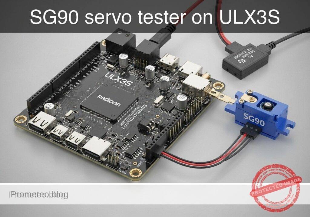
What you’ll build: A bench servo tester on the Radiona ULX3S (Lattice ECP5-85F) that generates a hobby-servo PWM control signal for an SG90 micro servo powered from an external 5 V supply. Four on-board buttons select center, minimum, maximum, or an automatic sweep mode, with a nominal 50 Hz update rate and ~1.0 ms, ~1.5 ms, or ~2.0 ms pulse widths.
Why it matters / Use cases
- Quickly validate SG90-style servos on the bench without needing a microcontroller or full robot control stack.
- Practice FPGA timing design using a real-world low-rate PWM task: 20 ms frame period, millisecond-scale pulses, and clean button-driven mode selection.
- Useful for troubleshooting wiring, endpoint response, and sweep behavior with a scope or logic analyzer by checking 50 FPS-equivalent control frames and pulse-width changes.
- Provides a simple hardware demo with very low FPGA load, typically only a tiny fraction of the ECP5 fabric and negligible overall GPU/graphics usage relevance.
Expected outcome
- The FPGA outputs a servo control frame near 20 ms (about 50 Hz).
- Button selection produces pulse widths near 1.0 ms, 1.5 ms, and 2.0 ms for minimum, center, and maximum positions.
- Sweep mode steps or ramps the pulse width across repeated frames so the servo moves back and forth with predictable timing.
- The project completes a standard open FPGA flow: Verilator lint, Yosys synthesis, nextpnr-ecp5 place-and-route, ecppack bitstream generation, and openFPGALoader programming.
- Measurement with a scope or logic analyzer confirms frame period accuracy and visible pulse-width changes for each mode, with control latency bounded to the next 20 ms frame.
Audience: FPGA beginners, digital design students, and embedded hardware makers; Level: Beginner to intermediate
Architecture/flow: Button inputs feed a mode selector in FPGA logic; a counter/timer generates the 20 ms servo frame and PWM high-time; the ULX3S outputs the control signal to the SG90 while the servo itself is powered from an external 5 V supply with shared ground; validate timing in simulation/build tools, then verify ~1.0/1.5/2.0 ms pulses and sweep behavior on hardware.
Educational validation note
Before publication, this case passed the Prometeo automated validation gate with status PASS. For this FPGA/ULX3S profile, the synthesizable Verilog blocks were checked with Yosys (read_verilog) and the Verilog design/test set was linted with Verilator. The validator also checked code-block structure, copy/paste-safe ASCII command options, unsupported stacks, and availability of the ULX3S/ECP5 toolchain (yosys, nextpnr-ecp5, ecppack, openFPGALoader).
Published validation evidence
- Automatic result: PASS.
- Parsed structure: 41 sections, 1 tables and 15 code blocks detected in the published content.
- Checked code: 3 Verilog/Yosys-Verilator, 9 Bash/copy-paste checks.
- Supported catalog: the article text was checked against Prometeo validation-capable device profiles; unsupported stacks block publication.
- Report findings: no blocking findings.
This validation confirms syntax and tool compatibility for the published code, but it does not replace physical testing on your exact ULX3S board revision, pin-constraint file and real wiring.
Educational safety note
This project is an educational prototype, not a certified product. Before powering the setup, verify the pinout of your exact ULX3S board revision, keep FPGA I/O signals at 3.3 V, never connect 5 V directly to I/O pins, disconnect power before changing wiring, and use suitable external supplies for loads, motors or servos while sharing ground only when the wiring requires it.
Conceptual block diagram
High-level view: what enters the system, what each block processes, and what comes out.
Functional architecture
Conceptual control flow: button input, mode selection, PWM timing and servo motion.

Validation path
The automated validation checks syntax, simulation/lint and compatibility with the ULX3S/ECP5 toolchain.

Prerequisites
Materials
| Item | Exact model | Quantity | Notes |
|---|---|---|---|
| FPGA board | Radiona ULX3S (Lattice ECP5-85F) | 1 | Target board |
| Servo | SG90 micro servo | 1 | 3-wire hobby servo |
| Servo supply | External 5 V servo supply | 1 | Must handle servo current spikes |
| USB cable | ULX3S-compatible USB cable | 1 | Board power and programming |
| Jumper wires | Suitable jumper wires | Several | Signal and ground wiring |
| Oscilloscope or logic analyzer | Any basic model | Optional but recommended | For waveform validation |
Wiring
Servo wires
Typical SG90 wire colors:
- brown/black: GND
- red: +5 V
- orange/yellow/white: control signal
Connections
- Power the ULX3S from USB.
- Power the servo from the external 5 V supply.
- Tie external 5 V ground to a ULX3S ground.
- Connect the FPGA output pin
servo_pwmto the servo signal wire.
Visible safety note
Educational safety note
This project drives a moving actuator from an external power source.
- Keep fingers and loose wires away from the servo horn while powered.
- Do not power the servo from an FPGA I/O pin.
- Do not connect 5 V directly to any ULX3S I/O.
- Always connect the grounds together so the signal has a valid reference.
- If the servo stalls, chatters loudly, or gets hot, power it down and inspect the linkage.
Button mapping
This tutorial uses four button inputs:
btn_center: center positionbtn_min: minimum positionbtn_max: maximum positionbtn_sweep: sweep mode
If no button is pressed, the design defaults to center.
Source code
File: src/servo_tester.v
Public preview of the validated file. The complete source is shown to members and in PDF/Print.
`timescale 1ns/1ps

module servo_tester #(
    parameter integer CLK_HZ = 25000000,
    parameter integer FRAME_HZ = 50,
    parameter integer PULSE_MIN_US = 1000,
    parameter integer PULSE_CENTER_US = 1500,
    parameter integer PULSE_MAX_US = 2000,
    parameter integer SWEEP_STEP_US = 10,
    parameter integer SWEEP_UPDATE_MS = 20
) (
    input  wire clk,
    input  wire btn_center,
    input  wire btn_min,
    input  wire btn_max,
    input  wire btn_sweep,
    output reg  servo_pwm
);

    localparam integer US_TICKS            = CLK_HZ / 1000000;
    localparam integer FRAME_TICKS         = CLK_HZ / FRAME_HZ;
    localparam integer PULSE_MIN_TICKS     = PULSE_MIN_US * US_TICKS;
    localparam integer PULSE_CENTER_TICKS  = PULSE_CENTER_US * US_TICKS;
    localparam integer PULSE_MAX_TICKS     = PULSE_MAX_US * US_TICKS;
    localparam integer SWEEP_STEP_TICKS    = SWEEP_STEP_US * US_TICKS;
    localparam integer SWEEP_UPDATE_TICKS  = (CLK_HZ / 1000) * SWEEP_UPDATE_MS;

    reg [31:0] frame_counter = 32'd0;
    reg [31:0] pulse_ticks   = PULSE_CENTER_TICKS;
    reg [31:0] sweep_counter = 32'd0;
    reg [31:0] sweep_ticks   = PULSE_CENTER_TICKS;
    reg        sweep_dir_up  = 1'b1;

    always @(posedge clk) begin
        if (btn_min) begin
            pulse_ticks   <= PULSE_MIN_TICKS;
            sweep_counter <= 32'd0;
            sweep_ticks   <= PULSE_CENTER_TICKS;
            sweep_dir_up  <= 1'b1;
        end else if (btn_center) begin
            pulse_ticks   <= PULSE_CENTER_TICKS;
            sweep_counter <= 32'd0;
            sweep_ticks   <= PULSE_CENTER_TICKS;
            sweep_dir_up  <= 1'b1;
        end else if (btn_max) begin
            pulse_ticks   <= PULSE_MAX_TICKS;
            sweep_counter <= 32'd0;
// ...`timescale 1ns/1ps
module servo_tester #(
parameter integer CLK_HZ = 25000000,
parameter integer FRAME_HZ = 50,
parameter integer PULSE_MIN_US = 1000,
parameter integer PULSE_CENTER_US = 1500,
parameter integer PULSE_MAX_US = 2000,
parameter integer SWEEP_STEP_US = 10,
parameter integer SWEEP_UPDATE_MS = 20
) (
input wire clk,
input wire btn_center,
input wire btn_min,
input wire btn_max,
input wire btn_sweep,
output reg servo_pwm
);
localparam integer US_TICKS = CLK_HZ / 1000000;
localparam integer FRAME_TICKS = CLK_HZ / FRAME_HZ;
localparam integer PULSE_MIN_TICKS = PULSE_MIN_US * US_TICKS;
localparam integer PULSE_CENTER_TICKS = PULSE_CENTER_US * US_TICKS;
localparam integer PULSE_MAX_TICKS = PULSE_MAX_US * US_TICKS;
localparam integer SWEEP_STEP_TICKS = SWEEP_STEP_US * US_TICKS;
localparam integer SWEEP_UPDATE_TICKS = (CLK_HZ / 1000) * SWEEP_UPDATE_MS;
reg [31:0] frame_counter = 32'd0;
reg [31:0] pulse_ticks = PULSE_CENTER_TICKS;
reg [31:0] sweep_counter = 32'd0;
reg [31:0] sweep_ticks = PULSE_CENTER_TICKS;
reg sweep_dir_up = 1'b1;
always @(posedge clk) begin
if (btn_min) begin
pulse_ticks <= PULSE_MIN_TICKS;
sweep_counter <= 32'd0;
sweep_ticks <= PULSE_CENTER_TICKS;
sweep_dir_up <= 1'b1;
end else if (btn_center) begin
pulse_ticks <= PULSE_CENTER_TICKS;
sweep_counter <= 32'd0;
sweep_ticks <= PULSE_CENTER_TICKS;
sweep_dir_up <= 1'b1;
end else if (btn_max) begin
pulse_ticks <= PULSE_MAX_TICKS;
sweep_counter <= 32'd0;
            sweep_ticks   <= PULSE_CENTER_TICKS;
            sweep_dir_up  <= 1'b1;
        end else if (btn_sweep) begin
            pulse_ticks <= sweep_ticks;

            if (sweep_counter >= (SWEEP_UPDATE_TICKS - 1)) begin
                sweep_counter <= 32'd0;

                if (sweep_dir_up) begin
                    if (sweep_ticks >= (PULSE_MAX_TICKS - SWEEP_STEP_TICKS)) begin
                        sweep_ticks  <= PULSE_MAX_TICKS;
                        sweep_dir_up <= 1'b0;
                    end else begin
                        sweep_ticks <= sweep_ticks + SWEEP_STEP_TICKS;
                    end
                end else begin
                    if (sweep_ticks <= (PULSE_MIN_TICKS + SWEEP_STEP_TICKS)) begin
                        sweep_ticks  <= PULSE_MIN_TICKS;
                        sweep_dir_up <= 1'b1;
                    end else begin
                        sweep_ticks <= sweep_ticks - SWEEP_STEP_TICKS;
                    end
                end
            end else begin
                sweep_counter <= sweep_counter + 32'd1;
            end
        end else begin
            pulse_ticks   <= PULSE_CENTER_TICKS;
sweep_counter <= 32'd0;
sweep_ticks <= PULSE_CENTER_TICKS;
sweep_dir_up <= 1'b1;
end
if (frame_counter >= (FRAME_TICKS - 1)) begin
frame_counter <= 32'd0;
end else begin
frame_counter <= frame_counter + 32'd1;
end
if (frame_counter < pulse_ticks) begin
servo_pwm <= 1'b1;
end else begin
servo_pwm <= 1'b0;
end
end
endmodule
File: tb/servo_tester_tb.v
Public preview of the validated file. The complete source is shown to members and in PDF/Print.
`timescale 1ns/1ps

module servo_tester_tb;

    reg clk = 1'b0;
    reg btn_center = 1'b0;
    reg btn_min = 1'b0;
    reg btn_max = 1'b0;
    reg btn_sweep = 1'b0;
    wire servo_pwm;

    integer high_count;
    integer i;

    servo_tester #(
        .CLK_HZ(1000000),
        .FRAME_HZ(50),
        .PULSE_MIN_US(1000),
        .PULSE_CENTER_US(1500),
        .PULSE_MAX_US(2000),
        .SWEEP_STEP_US(100),
        .SWEEP_UPDATE_MS(20)
    ) dut (
        .clk(clk),
        .btn_center(btn_center),
        .btn_min(btn_min),
        .btn_max(btn_max),
        .btn_sweep(btn_sweep),
        .servo_pwm(servo_pwm)
    );

    always #500 clk = ~clk;

    task automatic measure_one_frame;
        begin
            while (servo_pwm !== 1'b1) begin
                @(posedge clk);
            end

            high_count = 0;
// ...`timescale 1ns/1ps
module servo_tester_tb;
reg clk = 1'b0;
reg btn_center = 1'b0;
reg btn_min = 1'b0;
reg btn_max = 1'b0;
reg btn_sweep = 1'b0;
wire servo_pwm;
integer high_count;
integer i;
servo_tester #(
.CLK_HZ(1000000),
.FRAME_HZ(50),
.PULSE_MIN_US(1000),
.PULSE_CENTER_US(1500),
.PULSE_MAX_US(2000),
.SWEEP_STEP_US(100),
.SWEEP_UPDATE_MS(20)
) dut (
.clk(clk),
.btn_center(btn_center),
.btn_min(btn_min),
.btn_max(btn_max),
.btn_sweep(btn_sweep),
.servo_pwm(servo_pwm)
);
always #500 clk = ~clk;
task automatic measure_one_frame;
begin
while (servo_pwm !== 1'b1) begin
@(posedge clk);
end
high_count = 0;
            while (servo_pwm === 1'b1) begin
                @(posedge clk);
                high_count = high_count + 1;
            end

            $display("Measured high ticks: %0d", high_count);
        end
    endtask

    initial begin
        $display("Starting servo_tester_tb");

        btn_center = 1'b1;
        repeat (3) begin
            measure_one_frame();
        end
        btn_center = 1'b0;

        btn_min = 1'b1;
        repeat (3) begin
            measure_one_frame();
        end
        btn_min = 1'b0;

        btn_max = 1'b1;
        repeat (3) begin
            measure_one_frame();
        end
btn_max = 1'b0;
btn_sweep = 1'b1;
for (i = 0; i < 8; i = i + 1) begin
measure_one_frame();
end
btn_sweep = 1'b0;
$display("Testbench complete");
$finish;
end
endmodule
File: constraints/ulx3s_servo.lpf
Use valid ULX3S site names for your exact board revision.
BLOCK RESETPATHS;
BLOCK ASYNCPATHS;

FREQUENCY PORT "clk" 25.0 MHz;

LOCATE COMP "clk" SITE "CLK25";
IOBUF PORT "clk" IO_TYPE=LVCMOS33;

LOCATE COMP "btn_center" SITE "BTN1";
IOBUF PORT "btn_center" IO_TYPE=LVCMOS33 PULLMODE=UP;

LOCATE COMP "btn_min" SITE "BTN2";
IOBUF PORT "btn_min" IO_TYPE=LVCMOS33 PULLMODE=UP;

LOCATE COMP "btn_max" SITE "BTN3";
IOBUF PORT "btn_max" IO_TYPE=LVCMOS33 PULLMODE=UP;

LOCATE COMP "btn_sweep" SITE "BTN4";
IOBUF PORT "btn_sweep" IO_TYPE=LVCMOS33 PULLMODE=UP;

LOCATE COMP "servo_pwm" SITE "GPIO0";
IOBUF PORT "servo_pwm" IO_TYPE=LVCMOS33 DRIVE=4;
Active-low button wrapper
Many ULX3S button inputs are active-low. If your board wiring requires inversion, use a separate top-level wrapper for synthesis.
File: src/servo_tester_active_low.v
`timescale 1ns/1ps

module servo_tester_active_low (
    input  wire clk,
    input  wire btn_center_n,
    input  wire btn_min_n,
    input  wire btn_max_n,
    input  wire btn_sweep_n,
    output wire servo_pwm
);

    wire btn_center = ~btn_center_n;
    wire btn_min    = ~btn_min_n;
    wire btn_max    = ~btn_max_n;
    wire btn_sweep  = ~btn_sweep_n;

    servo_tester u_servo_tester (
        .clk(clk),
        .btn_center(btn_center),
        .btn_min(btn_min),
        .btn_max(btn_max),
        .btn_sweep(btn_sweep),
        .servo_pwm(servo_pwm)
    );

endmodule
If you use this wrapper, update the top module name in the synthesis command and rename the LPF ports to match:
btn_center_nbtn_min_nbtn_max_nbtn_sweep_n
Project layout
project/
├── build/
├── constraints/
│   └── ulx3s_servo.lpf
├── src/
│   ├── servo_tester.v
│   └── servo_tester_active_low.v
└── tb/
    └── servo_tester_tb.v
Build and program
1. Create the build directory
mkdir -p build
2. Run Verilator lint
verilator --lint-only -Wall -Wno-DECLFILENAME src/servo_tester.v tb/servo_tester_tb.v
If you synthesize the active-low wrapper, you can lint both source files:
verilator --lint-only -Wall -Wno-DECLFILENAME src/servo_tester.v src/servo_tester_active_low.v tb/servo_tester_tb.v
3. Synthesize with Yosys
For the direct top module:
yosys -p "read_verilog src/servo_tester.v; synth_ecp5 -top servo_tester -json build/servo_tester.json"
For the active-low wrapper top module:
yosys -p "read_verilog src/servo_tester.v src/servo_tester_active_low.v; synth_ecp5 -top servo_tester_active_low -json build/servo_tester.json"
4. Place and route
nextpnr-ecp5 --85k --package CABGA381 --json build/servo_tester.json --lpf constraints/ulx3s_servo.lpf --textcfg build/servo_tester.config
5. Pack the bitstream
ecppack build/servo_tester.config build/servo_tester.bit
6. Detect programmer
openFPGALoader --detect
7. Program the ULX3S
openFPGALoader -b ulx3s build/servo_tester.bit
Validation method
This project makes measurable timing claims, so validate them directly.
1. Toolchain evidence
Expected evidence:
- Verilator exits without fatal errors
- Yosys writes
build/servo_tester.json - nextpnr-ecp5 completes successfully
- ecppack writes
build/servo_tester.bit - openFPGALoader programs the board
2. Simulation evidence
The testbench runs at 1 MHz, so each high tick equals 1 us.
Expected evidence from $display output:
- center mode: about 1500 ticks
- min mode: about 1000 ticks
- max mode: about 2000 ticks
- sweep mode: values that change between repeated measurements
3. Hardware waveform evidence
Before connecting the servo, probe servo_pwm with an oscilloscope or logic analyzer.
Expected evidence:
- frame period near 20 ms
- pulse width near:
- 1.0 ms for minimum
- 1.5 ms for center
- 2.0 ms for maximum
- in sweep mode, pulse width changes over time
4. Functional servo evidence
After waveform validation:
- power down the servo supply
- connect the servo signal to
servo_pwm - connect servo ground to supply ground
- connect supply ground to ULX3S ground
- power the ULX3S
- power the external 5 V servo supply
Expected evidence:
- center button moves the servo to a repeatable middle position
- min and max move toward opposite ends
- sweep mode moves the servo back and forth
Troubleshooting
No servo motion
Check:
- external 5 V supply is on
- servo red wire goes to +5 V
- servo ground is connected
- ULX3S ground and servo supply ground are connected together
- correct FPGA output pin is assigned in the LPF
- the bitstream was actually programmed
Servo twitches but does not follow commands
Common causes:
- missing common ground
- wrong pin mapping in the LPF
- weak or unstable 5 V servo supply
- button polarity mismatch
nextpnr reports LPF site errors
The LPF site names must match your exact ULX3S board revision. Update:
CLK25BTN1BTN2BTN3BTN4GPIO0
to the valid names from your board documentation.
Modes appear inverted or stuck
Your buttons are likely active-low. Use the servo_tester_active_low wrapper and synthesize that top module instead.
Final checklist
- [ ] I used the Radiona ULX3S (Lattice ECP5-85F)
- [ ] I used an SG90 micro servo
- [ ] I powered the servo from an external 5 V supply
- [ ] I connected servo supply ground to ULX3S ground
- [ ] I verified the PWM waveform before connecting the servo
- [ ] Verilator lint passed
- [ ] Yosys synthesis passed
- [ ] nextpnr-ecp5 place-and-route passed
- [ ] ecppack generated a bitstream
- [ ] openFPGALoader programmed the board
- [ ] I measured about 1.0 ms, 1.5 ms, and 2.0 ms pulse widths for the expected modes
This produces a practical FPGA-based servo tester on the ULX3S ECP5-85F for quick bench validation of an SG90 servo.
Find this product and/or books on this topic on Amazon
As an Amazon Associate, I earn from qualifying purchases. If you buy through this link, you help keep this project running.
Quick Quiz

Telecommunications Electronics Engineer and Computer Engineer (official degrees in Spain).