
Objective and use case
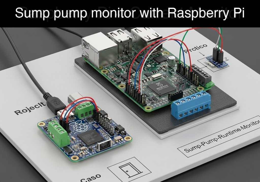
What you’ll build: A non-invasive current monitoring system that tracks the activation cycles and runtime duration of a sump pump using a Raspberry Pi 4 Model B.
Why it matters / Use cases
- Predictive maintenance: Detect unusually long pump runtimes indicating clogged intakes, worn bearings, or failing impellers before complete failure.
- Flood prevention: Trigger alerts if zero cycles are registered during heavy rain, signaling a potential power loss, tripped breaker, or float switch failure.
- Capacity analysis: Log cycle frequency during peak storms to determine if the pump is undersized or if a secondary backup pump is required.
- Energy auditing: Correlate runtime duration with power consumption to accurately calculate basement water management costs.
Expected outcome
- Continuous, low-latency analog sampling of the current sensor via the MCP3008 ADC.
- State-machine logic that reliably detects ON/OFF transitions based on an adjustable current threshold with <50ms response latency.
- Accurate, timestamped logging of total cycle counts and precise runtime durations.
Audience: IoT Developers, Home Automation Enthusiasts; Level: Intermediate
Architecture/flow: Non-invasive Current Sensor → MCP3008 ADC (via SPI) → Raspberry Pi 4 → State Machine Processing → Data Logging & Alerts
Educational validation note
Before publication, this case passed the Prometeo automated validation gate with status PASS. The validator checked the code blocks, article structure, copy/paste-safe commands and consistency with the supported device catalog.
Published validation evidence
- Automatic result: PASS.
- Parsed structure: 3 sections, 3 tables and 2 code blocks detected before publication.
- Checked code: 2 Python/py_compile.
- Supported catalog: the article text was checked against Prometeo’s validation-capable device profiles, and unsupported stacks block publication.
- Report findings: no blocking findings.
This validation confirms syntax and tool compatibility for the published material, but it does not replace physical testing on your exact hardware, wiring and runtime environment.
Educational safety note
This project is a low-voltage educational prototype, not a certified product. Before powering the setup, verify the pinout of your exact Raspberry Pi, never connect 5 V to 3.3 V GPIO pins, disconnect power before changing wiring, and use suitable interfaces or external supplies for sensors, relays, motors or loads.
Conceptual block diagram
High-level view: what enters the system, what each block processes, and what comes out.
Functional architecture
Conceptual signal and responsibility flow between device blocks.

Prerequisites
- Hardware: A Raspberry Pi 4 Model B with a 5V/3A USB-C power supply.
- Operating System: Raspberry Pi OS Bookworm 64-bit.
- Software: Python 3.11 installed (default on Bookworm).
- Configuration: SPI interface must be enabled in the Raspberry Pi OS.
- Knowledge: Basic familiarity with the Linux command line and Python script execution.
Materials
- Microcontroller: Raspberry Pi 4 Model B (any RAM configuration).
- ADC Module: MCP3008 (10-bit Analog-to-Digital Converter with SPI interface).
- Sensor: Opto-isolated current sensor module. (Note: For this basic tutorial, we assume a module that includes an integrated rectifier/envelope detector, outputting a steady DC voltage from 0V to 3.3V proportional to the AC current, rather than a raw AC sine wave).
- Prototyping: Standard breadboard and female-to-male / male-to-male jumper wires.
Setup/Connection
The MCP3008 uses the Serial Peripheral Interface (SPI) to communicate with the Raspberry Pi. The current sensor connects to the first channel (CH0) of the MCP3008.
Important: The MCP3008 will be powered by the Raspberry Pi’s 3.3V pin. Because the ADC reference voltage (VREF) is tied to 3.3V, the analog input from the sensor must never exceed 3.3V. Ensure your opto-isolated current sensor module is configured for 3.3V logic or has a maximum output of 3.3V.
Wiring Table
| Raspberry Pi 4B Pin | MCP3008 Pin | Sensor Module Pin | Function |
|---|---|---|---|
| Pin 1 (3.3V PWR) | VDD & VREF (Pins 16, 15) | VCC / 3.3V | Power supply and ADC reference |
| Pin 6 (GND) | AGND & DGND (Pins 14, 9) | GND | Common ground |
| Pin 23 (SCLK) | CLK (Pin 13) | – | SPI Clock |
| Pin 21 (MISO) | DOUT (Pin 12) | – | SPI Data Out (from ADC to Pi) |
| Pin 19 (MOSI) | DIN (Pin 11) | – | SPI Data In (from Pi to ADC) |
| Pin 24 (CE0) | CS/SHDN (Pin 10) | – | SPI Chip Select |
| – | CH0 (Pin 1) | OUT / Analog | Analog signal from current sensor |
Note: The opto-isolated current sensor clamp should be placed entirely around only one of the insulated AC wires (either the Live or the Neutral, never both) leading to the sump pump.
Validated Code
The software consists of two files. The first is a hardware abstraction layer (driver) for the MCP3008, which allows the code to run in a mock mode without physical hardware. The second is the main monitoring script containing the state machine and logging logic.
Create a directory for your project and save these files inside it.
File 1: mcp3008_driver.py
"""
mcp3008_driver.py
Hardware adapter for the MCP3008 SPI ADC.
Includes a mock implementation for dry-run validation.
"""

try:
    import spidev
    SPI_AVAILABLE = True
except ImportError:
    SPI_AVAILABLE = False

class MCP3008:
    def __init__(self, bus=0, device=0, mock=False):
        """
        Initializes the MCP3008 ADC.
        :param bus: SPI bus (default 0)
        :param device: SPI device/chip select (default 0 for CE0)
        :param mock: If True, bypasses hardware and uses simulated values.
        """
        self.mock = mock
        self.mock_val = 0

        if not self.mock:
            if not SPI_AVAILABLE:
                raise RuntimeError("spidev module not found. Install it or use --mock.")
            self.spi = spidev.SpiDev()
            self.spi.open(bus, device)
            self.spi.max_speed_hz = 1350000

    def read_channel(self, channel):
        """
        Reads a 10-bit analog value from the specified channel (0-7).
        :param channel: Integer from 0 to 7.
        :return: Integer from 0 to 1023.
        """
        if channel < 0 or channel > 7:
            raise ValueError("Channel must be an integer between 0 and 7")

        if self.mock:
            return self.mock_val

        # MCP3008 SPI protocol:
        # Byte 1: Start bit (1)
        # Byte 2: Single-ended mode (1) + 3-bit channel number, shifted left by 4
        # Byte 3: Don't care (0)
        command = [1, (8 + channel) << 4, 0]
        adc_response = self.spi.xfer2(command)

        # Extract the 10-bit response from the last two bytes
        data = ((adc_response[1] & 3) << 8) + adc_response[2]
        return data

    def close(self):
        """Closes the SPI connection."""
        if not self.mock:
            self.spi.close()
File 2: sump_monitor.py
Public preview of the validated file. The complete source is shown to members and in PDF/Print.
"""
sump_monitor.py
Main application for monitoring sump pump runtime.
Reads analog current data, applies threshold logic, and logs events to CSV.
"""

import argparse
import time
import datetime
import csv
import os
from mcp3008_driver import MCP3008

# Configuration
ADC_CHANNEL = 0
# Threshold out of 1023. Adjust based on your sensor's output when the pump is ON.
# 100 is roughly 0.32V on a 3.3V reference.
ON_THRESHOLD = 100
LOG_FILE = "sump_pump_log.csv"

def initialize_csv(filepath):
    """Creates the CSV file and writes headers if it doesn't exist."""
    if not os.path.exists(filepath):
        with open(filepath, mode='w', newline='') as file:
            writer = csv.writer(file)
            writer.writerow(["Timestamp_Start", "Timestamp_End", "Duration_Seconds", "Peak_ADC_Value"])
        print(f"[*] Created new log file: {filepath}")

def log_event(filepath, start_time, end_time, peak_val):
    """Appends a completed pump cycle to the CSV log."""
    duration = round(end_time - start_time, 2)
    start_str = datetime.datetime.fromtimestamp(start_time).strftime('%Y-%m-%d %H:%M:%S')
    end_str = datetime.datetime.fromtimestamp(end_time).strftime('%Y-%m-%d %H:%M:%S')

    with open(filepath, mode='a', newline='') as file:
        writer = csv.writer(file)
        writer.writerow([start_str, end_str, duration, peak_val])

    print(f"[LOG] Cycle recorded: {duration} seconds (Peak ADC: {peak_val})")

def simulate_environment(mcp, script_start_time):
    """
    Simulates a pump cycling on and off for dry-run validation.
    Pump turns ON for 5 seconds every 20 seconds.
    """
    elapsed = time.time() - script_start_time
    cycle_time = elapsed % 20
    if 5 <= cycle_time <= 10:
        # Simulate pump running (high current)
        mcp.mock_val = 650
    else:
        # Simulate pump off (noise floor)
        mcp.mock_val = 15
# ..."""
sump_monitor.py
Main application for monitoring sump pump runtime.
Reads analog current data, applies threshold logic, and logs events to CSV.
"""
import argparse
import time
import datetime
import csv
import os
from mcp3008_driver import MCP3008
# Configuration
ADC_CHANNEL = 0
# Threshold out of 1023. Adjust based on your sensor's output when the pump is ON.
# 100 is roughly 0.32V on a 3.3V reference.
ON_THRESHOLD = 100
LOG_FILE = "sump_pump_log.csv"
def initialize_csv(filepath):
"""Creates the CSV file and writes headers if it doesn't exist."""
if not os.path.exists(filepath):
with open(filepath, mode='w', newline='') as file:
writer = csv.writer(file)
writer.writerow(["Timestamp_Start", "Timestamp_End", "Duration_Seconds", "Peak_ADC_Value"])
print(f"[*] Created new log file: {filepath}")
def log_event(filepath, start_time, end_time, peak_val):
"""Appends a completed pump cycle to the CSV log."""
duration = round(end_time - start_time, 2)
start_str = datetime.datetime.fromtimestamp(start_time).strftime('%Y-%m-%d %H:%M:%S')
end_str = datetime.datetime.fromtimestamp(end_time).strftime('%Y-%m-%d %H:%M:%S')
with open(filepath, mode='a', newline='') as file:
writer = csv.writer(file)
writer.writerow([start_str, end_str, duration, peak_val])
print(f"[LOG] Cycle recorded: {duration} seconds (Peak ADC: {peak_val})")
def simulate_environment(mcp, script_start_time):
"""
Simulates a pump cycling on and off for dry-run validation.
Pump turns ON for 5 seconds every 20 seconds.
"""
elapsed = time.time() - script_start_time
cycle_time = elapsed % 20
if 5 <= cycle_time <= 10:
# Simulate pump running (high current)
mcp.mock_val = 650
else:
# Simulate pump off (noise floor)
mcp.mock_val = 15
def main():
    parser = argparse.ArgumentParser(description="Sump Pump Runtime Monitor")
    parser.add_argument("--mock", action="store_true", help="Run in mock mode without physical hardware")
    args = parser.parse_args()

    print("======================================")
    print("      Sump Pump Runtime Monitor       ")
    print("======================================")

    if args.mock:
        print("[!] Running in MOCK mode. Hardware bypassed.")
    else:
        print("[!] Running in HARDWARE mode.")

    initialize_csv(LOG_FILE)

    # Initialize ADC
    adc = MCP3008(bus=0, device=0, mock=args.mock)

    # State machine variables
    pump_is_running = False
    cycle_start_time = 0
    peak_adc_in_cycle = 0
    script_start_time = time.time()

    print(f"[*] Monitoring started. Press Ctrl+C to exit.")
    print(f"[*] Threshold set to ADC > {ON_THRESHOLD}")
try:
while True:
# Inject simulated data if in mock mode
if args.mock:
simulate_environment(adc, script_start_time)
# Read current sensor
current_val = adc.read_channel(ADC_CHANNEL)
# State Machine Logic
if current_val > ON_THRESHOLD:
if not pump_is_running:
# Transition: OFF -> ON
pump_is_running = True
cycle_start_time = time.time()
peak_adc_in_cycle = current_val
print(f"[{datetime.datetime.now().strftime('%H:%M:%S')}] PUMP ON DETECTED (ADC: {current_val})")
else:
# Update peak value during the cycle
if current_val > peak_adc_in_cycle:
peak_adc_in_cycle = current_val
else:
if pump_is_running:
# Transition: ON -> OFF
pump_is_running = False
cycle_end_time = time.time()
print(f"[{datetime.datetime.now().strftime('%H:%M:%S')}] PUMP OFF DETECTED")
log_event(LOG_FILE, cycle_start_time, cycle_end_time, peak_adc_in_cycle)
# Sample rate: ~10Hz is sufficient for this application
time.sleep(0.1)
except KeyboardInterrupt:
print("\n[*] Shutting down monitor gracefully...")
finally:
adc.close()
print("[*] Cleanup complete. Exiting.")
if __name__ == "__main__":
main()
Build/Flash/Run commands
To set up your Raspberry Pi and run the project, follow these commands.
Command Table
| Task | Command |
|---|---|
| Update packages | sudo apt-get update |
| Enable SPI interface | sudo raspi-config nonint do_spi 0 |
| Install SPI library | sudo apt-get install python3-spidev |
| Run validation (Mock) | python3 sump_monitor.py --mock |
| Run hardware monitor | python3 sump_monitor.py |
| View CSV log | cat sump_pump_log.csv |
Workflow
- Open an SSH terminal to your Raspberry Pi 4 Model B.
- Run the SPI enablement command and install
python3-spidev. - Create a project folder (e.g.,
mkdir ~/sump_monitor && cd ~/sump_monitor). - Create the two Python files using a text editor (e.g.,
nano mcp3008_driver.pyandnano sump_monitor.py) and paste the code. - Test the logic by running the mock command:
python3 sump_monitor.py --mock. Let it run for at least 30 seconds to observe simulated pump cycles. - Connect your hardware, ensure the sensor is safely clamped around the correct wire, and start the live monitor:
python3 sump_monitor.py.
Step-by-step Validation
Use these checkpoints to ensure your system is functioning correctly.
- SPI Enablement Check
- Action: Run
ls /dev/spi*. - Expected Observation: You should see
/dev/spidev0.0and/dev/spidev0.1. - Pass Condition: Devices are listed, confirming the OS has enabled the SPI bus.
- Action: Run
- Mock Mode Validation
- Action: Execute
python3 sump_monitor.py --mock. Wait 25 seconds. - Expected Observation: Console outputs
PUMP ON DETECTEDfollowed 5 seconds later byPUMP OFF DETECTEDand a[LOG] Cycle recordedmessage. - Pass Condition: The state machine successfully detects transitions and calculates a duration of ~5.0 seconds without hardware attached.
- Action: Execute
- Hardware Baseline Check
- Action: Connect the hardware. Keep the pump OFF. Run
python3 sump_monitor.py. (You may want to add a temporaryprint(current_val)inside the loop to see raw data). - Expected Observation: The ADC value remains consistently low (e.g., between 0 and 20).
- Pass Condition: The baseline noise floor is safely below the
ON_THRESHOLD(100).
- Action: Connect the hardware. Keep the pump OFF. Run
- Hardware Active Check
- Action: Manually trigger the sump pump (e.g., lift the float switch slightly or pour water into the pit).
- Expected Observation: The script immediately prints
PUMP ON DETECTED. - Pass Condition: The ADC value spikes above 100, triggering the state machine.
- Data Logging Check
- Action: Stop the script (
Ctrl+C). Runcat sump_pump_log.csv. - Expected Observation: The CSV contains headers and at least one row of data with valid timestamps and non-zero durations.
- Pass Condition: File format is correct and data is successfully persisted to the disk.
- Action: Stop the script (
Troubleshooting
| Symptom | Likely cause | Fix |
|---|---|---|
ModuleNotFoundError: No module named 'spidev' | SPI library is not installed. | Run sudo apt-get install python3-spidev. |
PermissionError: [Errno 13] Permission denied | User is not in the spi or gpio group. | Run `sudo us |
Find this product and/or books on this topic on Amazon
As an Amazon Associate, I earn from qualifying purchases. If you buy through this link, you help keep this project running.
Quick Quiz

Telecommunications Electronics Engineer and Computer Engineer (official degrees in Spain).

