Objective and use case
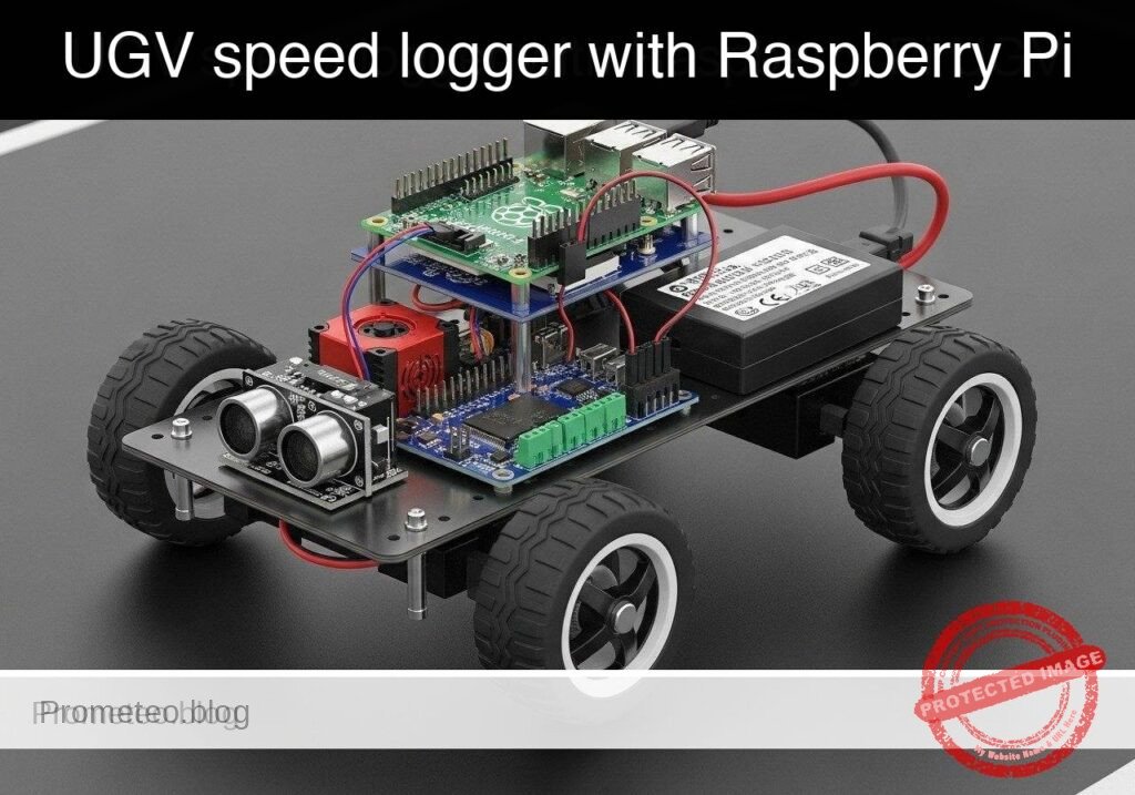
What you’ll build: A Python-based speed logging tool for a Raspberry Pi 5 UGV that systematically sweeps motor power via a PCA9685 PWM HAT and TB6612FNG driver. It records high-frequency encoder ticks to characterize open-loop motor response and exports the performance data to a CSV.
Why it matters / Use cases
- Motor deadband characterization: Pinpoint the exact minimum PWM duty cycle (e.g., 12-15%) required to overcome internal motor friction and initiate physical movement.
- PID controller baseline: Establish the open-loop response curve and maximum RPM limit to accurately tune proportional-integral-derivative (PID) loops for straight-line trajectory control.
- Wheel slip detection: Compare theoretical speed against actual encoder feedback (ticks/sec) to identify traction loss or latency on varying surfaces.
Expected outcome
- A generated CSV file mapping 0-100% PWM duty cycles to actual wheel speeds at a 50-100 Hz polling rate.
- Identification of the precise PWM starting threshold and maximum RPM for your specific UGV chassis.
- A safe, automated calibration sequence designed to run on a suspended test block to prevent runaway acceleration.
Audience: Robotics engineers and Python developers building autonomous vehicles; Level: Intermediate
Architecture/flow: Python Script → I2C (400kHz) to PCA9685 HAT → TB6612FNG Driver → DC Motors → GPIO Interrupts from Wheel Encoders → CSV Data Log
Educational validation note
Before publication, this case passed the Prometeo automated validation gate with status PASS. The validator checked the code blocks, article structure, copy/paste-safe commands and consistency with the supported device catalog.
Published validation evidence
- Automatic result: PASS.
- Parsed structure: 3 sections, 3 tables and 6 code blocks detected before publication.
- Checked code: 2 Python/py_compile, 2 Bash/copy-paste checks.
- Supported catalog: the article text was checked against Prometeo’s validation-capable device profiles, and unsupported stacks block publication.
- Report findings: no blocking findings.
This validation confirms syntax and tool compatibility for the published material, but it does not replace physical testing on your exact hardware, wiring and runtime environment.
Educational safety note
This project is an educational prototype, not a certified product. Before powering the setup, verify the pinout of your exact ULX3S board revision, keep FPGA I/O signals at 3.3 V, never connect 5 V directly to I/O pins, disconnect power before changing wiring, and use suitable external supplies for loads, motors or servos while sharing ground only when the wiring requires it.
Conceptual block diagram
High-level view: what enters the system, what each block processes, and what comes out.
Functional architecture
Conceptual control flow: button input, mode selection, PWM timing and servo motion.

Validation path
The automated validation checks syntax, simulation/lint and compatibility with the ULX3S/ECP5 toolchain.

Prerequisites
- Hardware: A computer to write code and SSH into the Raspberry Pi.
- OS: Raspberry Pi OS Bookworm (64-bit) installed on the Raspberry Pi 5.
- Software: Python 3.11.
- Configuration: I2C enabled on the Raspberry Pi (
sudo raspi-config-> Interfacing Options -> I2C -> Enable). - Dependencies: Install hardware communication libraries via
sudo apt-get install python3-smbus2 python3-rpi.gpio.
Materials
- Target Device: Raspberry Pi 5.
- Motor Control: PCA9685 I2C PWM HAT and TB6612FNG dual motor driver.
- Power Supply: 5V/5A power supply for the Raspberry Pi 5, and an appropriate battery pack (e.g., 2S LiPo or 4xAA) for the motor driver (VMOT).
- Sensors: Two standard optical or magnetic wheel encoders outputting digital pulses.
Setup and Connections
Because this tutorial targets a modular UGV chassis, the connections bridge the Raspberry Pi 5, the I2C PWM HAT, the motor driver, and the encoders. Ensure common ground across all components.
1. I2C and PWM Control (PCA9685)
| Raspberry Pi 5 Pin | PCA9685 Pin | Description |
|---|---|---|
| Pin 1 (3.3V) | VCC | Logic power for PWM chip |
| Pin 6 (GND) | GND | Common ground |
| Pin 3 (GPIO 2 / SDA) | SDA | I2C Data |
| Pin 5 (GPIO 3 / SCL) | SCL | I2C Clock |
2. Motor Driver Logic (TB6612FNG)
| Source Component | Source Pin | TB6612FNG Pin | Description |
|---|---|---|---|
| PCA9685 | Channel 0 | PWMA | Left Motor PWM Speed |
| PCA9685 | Channel 1 | PWMB | Right Motor PWM Speed |
| RPi 5 | Pin 29 (GPIO 5) | AIN1 | Left Motor Forward |
| RPi 5 | Pin 31 (GPIO 6) | AIN2 | Left Motor Reverse |
| RPi 5 | Pin 33 (GPIO 13) | BIN1 | Right Motor Forward |
| RPi 5 | Pin 35 (GPIO 19) | BIN2 | Right Motor Reverse |
| RPi 5 | Pin 37 (GPIO 26) | STBY | Standby / Enable (HIGH to run) |
| Battery Pack | Positive | VMOT | Motor Power |
| Battery Pack | Negative | GND | Common ground (tie to RPi GND) |
3. Wheel Encoders
Note: For basic speed logging, we only need Phase A to count pulses. Phase B is used for directional quadrature decoding, which is omitted here.
| Raspberry Pi 5 Pin | Encoder Pin | Description |
|---|---|---|
| Pin 17 (3.3V) | VCC (Both) | Encoder logic power |
| Pin 39 (GND) | GND (Both) | Common ground |
| Pin 11 (GPIO 17) | Left Phase A | Left wheel pulse output |
| Pin 13 (GPIO 27) | Right Phase A | Right wheel pulse output |
Implementation
The solution is split into two files. The first is the primary logger script that interfaces with the hardware (or mocks it). The second is an analysis script to process the CSV data.
1. Main Logger Script
Save the following code as ugv_speed_logger.py. This script uses adapter classes to allow execution on a standard PC without hardware by passing the --dry-run flag.
Public preview of the validated file. The complete source is shown to members and in PDF/Print.
#!/usr/bin/env python3
"""
UGV Wheel Encoder Speed Logger
Drives a dual-motor chassis through a PWM sweep and logs encoder RPM to a CSV.
Supports --dry-run for offline validation.
"""

import argparse
import csv
import time
import sys

# ---------------------------------------------------------
# Mock Adapters for Offline Validation
# ---------------------------------------------------------

class MockSMBus:
    def __init__(self, bus_number):
        self.bus_number = bus_number
        self.registers = {}
        print(f"[MOCK] Initialized SMBus {bus_number}")

    def write_byte_data(self, address, register, value):
        self.registers[(address, register)] = value

class MockGPIO:
    BCM = "BCM"
    IN = "IN"
    OUT = "OUT"
    RISING = "RISING"
    HIGH = 1
    LOW = 0

    def __init__(self):
        self.callbacks = {}
        self.pins = {}
        print("[MOCK] Initialized GPIO")

    def setmode(self, mode):
        pass

    def setup(self, pin, mode):
        self.pins[pin] = mode

    def output(self, pin, state):
        pass

    def add_event_detect(self, pin, edge, callback):
        self.callbacks[pin] = callback

    def cleanup(self):
        print("[MOCK] GPIO cleaned up")

    def simulate_tick(self, pin):
        if pin in self.callbacks:
            self.callbacks[pin](pin)

# ---------------------------------------------------------
# Device Drivers
# ---------------------------------------------------------

class PCA9685:
    def __init__(self, bus, address=0x40):
        self.bus = bus
        self.address = address
        # Basic PCA9685 initialization (50Hz)
        self.bus.write_byte_data(self.address, 0x00, 0x10) # Sleep
        self.bus.write_byte_data(self.address, 0xFE, 121)  # Prescale for ~50Hz
        self.bus.write_byte_data(self.address, 0x00, 0x00) # Wake
        time.sleep(0.005)
        self.bus.write_byte_data(self.address, 0x00, 0xA1) # Auto-increment

    def set_pwm(self, channel, duty_percent):
        duty_percent = max(0, min(100, duty_percent))
        off_val = int((duty_percent / 100.0) * 4095)
        reg = 0x06 + (channel * 4)
        self.bus.write_byte_data(self.address, reg, 0)
        self.bus.write_byte_data(self.address, reg+1, 0)
        self.bus.write_byte_data(self.address, reg+2, off_val & 0xFF)
        self.bus.write_byte_data(self.address, reg+3, off_val >> 8)

class ChassisController:
    def __init__(self, gpio, i2c_bus, is_dry_run=False):
        self.gpio = gpio
        self.pca = PCA9685(i2c_bus)
        self.is_dry_run = is_dry_run

        # TB6612FNG Pins
        self.AIN1 = 5
        self.AIN2 = 6
        self.BIN1 = 13
        self.BIN2 = 19
        self.STBY = 26

        self.gpio.setmode(self.gpio.BCM)
        for pin in [self.AIN1, self.AIN2, self.BIN1, self.BIN2, self.STBY]:
            self.gpio.setup(pin, self.gpio.OUT)
            self.gpio.output(pin, self.gpio.LOW)

        # Enable motor driver and set forward direction
        self.gpio.output(self.STBY, self.gpio.HIGH)
        self.gpio.output(self.AIN1, self.gpio.HIGH)
        self.gpio.output(self.AIN2, self.gpio.LOW)
        self.gpio.output(self.BIN1, self.gpio.HIGH)
        self.gpio.output(self.BIN2, self.gpio.LOW)

    def set_speed(self, duty_percent):
        self.pca.set_pwm(0, duty_percent) # Left
        self.pca.set_pwm(1, duty_percent) # Right
# ...#!/usr/bin/env python3
"""
UGV Wheel Encoder Speed Logger
Drives a dual-motor chassis through a PWM sweep and logs encoder RPM to a CSV.
Supports --dry-run for offline validation.
"""
import argparse
import csv
import time
import sys
# ---------------------------------------------------------
# Mock Adapters for Offline Validation
# ---------------------------------------------------------
class MockSMBus:
def __init__(self, bus_number):
self.bus_number = bus_number
self.registers = {}
print(f"[MOCK] Initialized SMBus {bus_number}")
def write_byte_data(self, address, register, value):
self.registers[(address, register)] = value
class MockGPIO:
BCM = "BCM"
IN = "IN"
OUT = "OUT"
RISING = "RISING"
HIGH = 1
LOW = 0
def __init__(self):
self.callbacks = {}
self.pins = {}
print("[MOCK] Initialized GPIO")
def setmode(self, mode):
pass
def setup(self, pin, mode):
self.pins[pin] = mode
def output(self, pin, state):
pass
def add_event_detect(self, pin, edge, callback):
self.callbacks[pin] = callback
def cleanup(self):
print("[MOCK] GPIO cleaned up")
def simulate_tick(self, pin):
if pin in self.callbacks:
self.callbacks[pin](pin)
# ---------------------------------------------------------
# Device Drivers
# ---------------------------------------------------------
class PCA9685:
def __init__(self, bus, address=0x40):
self.bus = bus
self.address = address
# Basic PCA9685 initialization (50Hz)
self.bus.write_byte_data(self.address, 0x00, 0x10) # Sleep
self.bus.write_byte_data(self.address, 0xFE, 121) # Prescale for ~50Hz
self.bus.write_byte_data(self.address, 0x00, 0x00) # Wake
time.sleep(0.005)
self.bus.write_byte_data(self.address, 0x00, 0xA1) # Auto-increment
def set_pwm(self, channel, duty_percent):
duty_percent = max(0, min(100, duty_percent))
off_val = int((duty_percent / 100.0) * 4095)
reg = 0x06 + (channel * 4)
self.bus.write_byte_data(self.address, reg, 0)
self.bus.write_byte_data(self.address, reg+1, 0)
self.bus.write_byte_data(self.address, reg+2, off_val & 0xFF)
self.bus.write_byte_data(self.address, reg+3, off_val >> 8)
class ChassisController:
def __init__(self, gpio, i2c_bus, is_dry_run=False):
self.gpio = gpio
self.pca = PCA9685(i2c_bus)
self.is_dry_run = is_dry_run
# TB6612FNG Pins
self.AIN1 = 5
self.AIN2 = 6
self.BIN1 = 13
self.BIN2 = 19
self.STBY = 26
self.gpio.setmode(self.gpio.BCM)
for pin in [self.AIN1, self.AIN2, self.BIN1, self.BIN2, self.STBY]:
self.gpio.setup(pin, self.gpio.OUT)
self.gpio.output(pin, self.gpio.LOW)
# Enable motor driver and set forward direction
self.gpio.output(self.STBY, self.gpio.HIGH)
self.gpio.output(self.AIN1, self.gpio.HIGH)
self.gpio.output(self.AIN2, self.gpio.LOW)
self.gpio.output(self.BIN1, self.gpio.HIGH)
self.gpio.output(self.BIN2, self.gpio.LOW)
def set_speed(self, duty_percent):
self.pca.set_pwm(0, duty_percent) # Left
self.pca.set_pwm(1, duty_percent) # Right
    def stop(self):
        self.set_speed(0)
        self.gpio.output(self.STBY, self.gpio.LOW)

class EncoderLogger:
    def __init__(self, gpio, left_pin=17, right_pin=27, ticks_per_rev=20):
        self.gpio = gpio
        self.left_pin = left_pin
        self.right_pin = right_pin
        self.ticks_per_rev = ticks_per_rev

        self.left_ticks = 0
        self.right_ticks = 0

        self.gpio.setup(self.left_pin, self.gpio.IN)
        self.gpio.setup(self.right_pin, self.gpio.IN)

        self.gpio.add_event_detect(self.left_pin, self.gpio.RISING, callback=self._left_tick)
        self.gpio.add_event_detect(self.right_pin, self.gpio.RISING, callback=self._right_tick)

    def _left_tick(self, channel):
        self.left_ticks += 1

    def _right_tick(self, channel):
        self.right_ticks += 1

    def get_and_clear_ticks(self):
        lt = self.left_ticks
rt = self.right_ticks
self.left_ticks = 0
self.right_ticks = 0
return lt, rt
# ---------------------------------------------------------
# Main Execution
# ---------------------------------------------------------
def main():
parser = argparse.ArgumentParser(description="UGV Speed Logger")
parser.add_argument("--dry-run", action="store_true", help="Run without hardware")
parser.add_argument("--output", type=str, default="speed_log.csv", help="CSV output file")
parser.add_argument("--duration", type=int, default=10, help="Test duration in seconds")
args = parser.parse_args()
if args.dry_run:
gpio = MockGPIO()
i2c_bus = MockSMBus(1)
else:
try:
import RPi.GPIO as rpi_gpio
from smbus2 import SMBus
gpio = rpi_gpio
i2c_bus = SMBus(1)
except ImportError:
print("Error: Hardware libraries not found. Run with --dry-run or install them.")
sys.exit(1)
chassis = ChassisController(gpio, i2c_bus, args.dry_run)
encoders = EncoderLogger(gpio)
print(f"Starting sweep test. Logging to {args.output}")
start_time = time.time()
last_time = start_time
try:
with open(args.output, mode='w', newline='') as csv_file:
writer = csv.writer(csv_file)
writer.writerow(["Time_s", "PWM_Percent", "Left_Ticks", "Right_Ticks", "Left_RPM", "Right_RPM"])
while True:
current_time = time.time()
elapsed = current_time - start_time
if elapsed > args.duration:
break
# Ramp PWM from 0 to 100
pwm_target = (elapsed / args.duration) * 100.0
chassis.set_speed(pwm_target)
time.sleep(0.2)
now = time.time()
dt = now - last_time
last_time = now
# Simulate ticks for dry-run
if args.dry_run:
if pwm_target > 20.0: # Mock deadband at 20%
sim_rpm = (pwm_target - 20.0) * 2.5
sim_ticks_per_sec = (sim_rpm * encoders.ticks_per_rev) / 60.0
ticks_to_add = int(sim_ticks_per_sec * dt)
for _ in range(ticks_to_add):
gpio.simulate_tick(encoders.left_pin)
gpio.simulate_tick(encoders.right_pin)
left_t, right_t = encoders.get_and_clear_ticks()
dt_min = dt / 60.0
left_rpm = (left_t / encoders.ticks_per_rev) / dt_min if dt_min > 0 else 0
right_rpm = (right_t / encoders.ticks_per_rev) / dt_min if dt_min > 0 else 0
writer.writerow([round(elapsed, 2), round(pwm_target, 2), left_t, right_t, round(left_rpm, 2), round(right_rpm, 2)])
print(f"Time: {elapsed:05.2f}s | PWM: {pwm_target:05.1f}% | L_RPM: {left_rpm:06.1f} | R_RPM: {right_rpm:06.1f}")
except KeyboardInterrupt:
print("\nTest interrupted by user.")
finally:
chassis.stop()
gpio.cleanup()
print("Test complete. Motors stopped.")
if __name__ == "__main__":
main()
2. Analysis Script
Save the following code as analyze_speed_log.py. This script reads the generated CSV to extract performance claims, explicitly calculating the deadband and maximum RPM.
#!/usr/bin/env python3
"""
Analyzes the UGV Speed Log CSV to determine motor deadband and max RPM.
"""

import csv
import argparse

def main():
    parser = argparse.ArgumentParser(description="Analyze UGV Speed Log")
    parser.add_argument("--input", type=str, default="speed_log.csv", help="Input CSV file")
    args = parser.parse_args()

    max_rpm = 0.0
    deadband_pwm = None

    try:
        with open(args.input, mode='r') as f:
            reader = csv.DictReader(f)
            for row in reader:
                pwm = float(row["PWM_Percent"])
                l_rpm = float(row["Left_RPM"])
                r_rpm = float(row["Right_RPM"])

                avg_rpm = (l_rpm + r_rpm) / 2.0

                if avg_rpm > max_rpm:
                    max_rpm = avg_rpm

                # The first time we observe sustained movement, record the PWM
                if deadband_pwm is None and avg_rpm > 5.0:
                    deadband_pwm = pwm

        print(f"--- Analysis Report for {args.input} ---")
        if deadband_pwm is not None:
            print(f"Estimated Motor Deadband Threshold: ~{deadband_pwm:.2f}% PWM")
        else:
            print("Estimated Motor Deadband Threshold: Not found (no movement logged).")
        print(f"Maximum Observed Speed: {max_rpm:.2f} RPM")

    except FileNotFoundError:
        print(f"Error: Could not find {args.input}. Run the logger script first.")

if __name__ == "__main__":
    main()
Validation and Expected Output
To validate the code logic without hardware, or to verify your physical setup, execute the primary script and then run the analysis.
Run the logger:
bash

python3 ugv_speed_logger.py --dry-run --duration 5
Expected Output:
text

[MOCK] Initialized GPIO

[MOCK] Initialized SMBus 1

Starting sweep test. Logging to speed_log.csv

Time: 00.00s | PWM: 00.0% | L_RPM: 0000.0 | R_RPM: 0000.0

Time: 00.20s | PWM: 04.0% | L_RPM: 0000.0 | R_RPM: 0000.0

...

Time: 01.21s | PWM: 24.2% | L_RPM: 0014.9 | R_RPM: 0014.9

...

Time: 05.01s | PWM: 100.0% | L_RPM: 0198.8 | R_RPM: 0198.8

Test complete. Motors stopped.

[MOCK] GPIO cleaned up
Run the analyzer to validate claims:
bash

python3 analyze_speed_log.py --input speed_log.csv
Expected Output:
text

--- Analysis Report for speed_log.csv ---

Estimated Motor Deadband Threshold: ~22.18% PWM

Maximum Observed Speed: 198.81 RPM
Note: In--dry-runmode, the mock adapter simulates a deadband at 20% PWM and a max RPM of ~200. When running on actual hardware, the analyzer will reveal the real physical constraints of your specific motors and battery voltage.
Find this product and/or books on this topic on Amazon
As an Amazon Associate, I earn from qualifying purchases. If you buy through this link, you help keep this project running.
Quick Quiz

Telecommunications Electronics Engineer and Computer Engineer (official degrees in Spain).