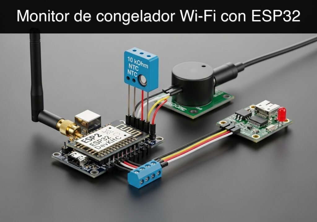
case-device-block-diagram, Qué construirás: Un sistema de monitorización de temperatura de congeladores con Wi-Fi que lee un termistor NTC analógico, activa una alarma local sonora y visual cuando las temperaturas superan un umbral seguro (por ejemplo, > -10°C) y sirve datos en tiempo real a un panel web local con una latencia de <1s. Público: Aficionados al IoT, estudiantes de electrónica e ingenieros de prototipos; Nivel: Intermedio Arquitectura/flujo: Termistor NTC → ADC del microcontrolador → Lógica de umbral (Zumbador/LED GPIO) → Punto de acceso/Estación Wi-Fi → Interfaz de usuario web local. Vista de alto nivel: qué entra, qué procesa cada bloque y qué sale del sistema. Flujo conceptual: detección de humedad, decisión local y aviso al usuario. Resumen conceptual de las herramientas usadas para comprobar el proyecto ESP32 publicado. Antes de publicar este caso, el contenido pasó la puerta automática de validación de Prometeo con estado PASS. Para este perfil ESP32 DevKitC, el proyecto se comprobó como proyecto PlatformIO: el validador extrajo Esta validación confirma compatibilidad sintáctica y de herramientas para el código publicado, pero no sustituye la prueba física sobre tu placa ESP32 DevKitC exacta, tu cableado, alimentación y entorno WiFi local. Este proyecto es un prototipo educativo de bajo voltaje, no un sistema certificado de alarma alimentaria. Verifica el pinout de tu ESP32 DevKitC y del sensor de temperatura, mantén todos los GPIO dentro de sus límites de 3,3 V y no conectes el circuito a la red eléctrica ni a la alimentación interna del congelador. Usa una fuente USB fiable, protege el cableado de la humedad y desconecta la alimentación antes de manipular el montaje. Antes de comenzar este tutorial, asegúrese de tener listo lo siguiente: Para garantizar que el código y el cableado se comporten exactamente como se describe, utilice los componentes precisos enumerados a continuación: La configuración del hardware requiere cablear cuidadosamente el termistor NTC en una configuración de divisor de voltaje, junto con los periféricos de salida. Nota de ingeniería importante sobre el ADC: Usamos GPIO34 para el termistor. GPIO34 pertenece al bloque El proyecto se basa en dos archivos dentro del entorno PlatformIO. Cree un nuevo proyecto en PlatformIO seleccionando la placa Este archivo de configuración define el objetivo de hardware, el framework y la velocidad de baudios del monitor serie. Este es el código fuente principal. Asegúrese de actualizar las variables Vista pública parcial del archivo validado. El código completo se muestra a miembros y en PDF/Print. Encuentra este producto y/o libros sobre este tema en Amazon Como afiliado de Amazon, gano con las compras que cumplan los requisitos. Si compras a través de este enlace, ayudas a mantener este proyecto.
.prometeo-educational-note,
.prometeo-device-postcode-section,
.prometeo-device-section-card {
margin: 2.4rem 0;
padding: 1.45rem 1.55rem;
border: 1px solid rgba(148, 163, 184, 0.30);
border-radius: 14px;
background:
linear-gradient(135deg, rgba(30, 41, 59, 0.50), rgba(15, 23, 42, 0.18)),
rgba(17, 24, 39, 0.48);
box-shadow: 0 18px 48px rgba(0, 0, 0, 0.20);
}
.case-objective > h2:first-of-type,
.case-device-block-diagram > h2:first-of-type,
.prometeo-device-postcode-section > h2:first-of-type,
.prometeo-device-section-card > h2:first-of-type {
margin-top: 0;
}
.prometeo-device-section-card > :last-child,
.case-objective > :last-child,
.case-device-block-diagram > :last-child,
.prometeo-device-postcode-section > :last-child {
margin-bottom: 0;
}
.prometeo-device-section-card.prometeo-device-section-card-code {
border-left: 4px solid rgba(56, 189, 248, 0.86);
background:
linear-gradient(135deg, rgba(8, 47, 73, 0.42), rgba(15, 23, 42, 0.18)),
rgba(15, 23, 42, 0.58);
}
.prometeo-device-section-card.prometeo-device-section-card-compact {
padding: 1.2rem 1.35rem;
}
.prometeo-device-section-card pre,
.case-objective pre,
.case-device-block-diagram pre,
.prometeo-device-postcode-section pre {
max-width: 100%;
}
.prometeo-device-postcode-section .prometeo-device-flow-item {
background:
linear-gradient(135deg, rgba(15, 23, 42, 0.50), rgba(30, 41, 59, 0.28)),
rgba(15, 23, 42, 0.28);
}
@media print {
.case-objective,
.case-device-block-diagram,
.prometeo-educational-note,
.prometeo-device-postcode-section,
.prometeo-device-section-card {
background: #fff;
color: #111827;
box-shadow: none;
break-inside: avoid;
page-break-inside: avoid;
}
}
Objetivo y caso de uso
Por qué es importante / Casos de uso
Resultado esperado
Diagrama de bloques conceptual
Arquitectura funcional
Ruta de validación
Nota educativa de validación
platformio.ini y src/main.cpp, creó un proyecto temporal y ejecutó pio run contra platform = espressif32, board = esp32dev y framework = arduino. También revisó la estructura del artículo, que los comandos sean copiables con guiones ASCII, y que no aparezcan stacks no soportados como ESP-IDF directo o placas ESP32 no acotadas.Evidencia de validación publicada
Nota educativa de seguridad
Requisitos previos
* Software: Visual Studio Code con la extensión PlatformIO IDE instalada.
* Conocimientos: Comprensión básica de programación en C++, divisores de voltaje y conceptos fundamentales de redes Wi-Fi.
* Red: Acceso a una red Wi-Fi estándar de 2.4 GHz (los microcontroladores ESP32 no soportan redes de 5 GHz).Materiales
Componente Especificación / Modelo exacto Cantidad Microcontrolador ESP32 DevKitC (variante de 38 pines o 30 pines) 1 Sensor de temperatura Termistor NTC de 10 kOhm (valor B ~3950) 1 Resistencia fija 10 kOhm (1/4 Watt, para el divisor de voltaje) 1 Resistencia limitadora de corriente 220 Ohm (1/4 Watt, para el LED) 1 Indicador visual LED de estado (Estándar de 5mm, preferiblemente rojo) 1 Indicador sonoro Zumbador activo (compatible con 3.3V o 5V) 1 Prototipado Protoboard y cables puente surtidos 1 juego Energía/Datos Cable de datos Micro-USB 1 Configuración/Conexión
ADC1 del ESP32. No utilice pines del ADC2 (como GPIO4 o GPIO2) porque el ADC2 es utilizado por el controlador Wi-Fi y no podrá leer voltajes analógicos mientras la radio Wi-Fi esté activa.1. Divisor de voltaje del termistor NTC
2. Zumbador activo
+ o la pata más larga) del zumbador activo al GPIO26.3. LED de estado
4. Configuración del controlador USB
Código validado
esp32dev y el framework Arduino. Reemplace el contenido de los archivos generados con el código a continuación.platformio.ini[env:esp32dev]
platform = espressif32
board = esp32dev
framework = arduino
monitor_speed = 115200
src/main.cppWIFI_SSID y WIFI_PASSWORD para que coincidan con las credenciales de su red local antes de compilar.#include <Arduino.h>
#include <WiFi.h>
#include <WebServer.h>
// ------------------------------------------------------------------
// Network Credentials
// ------------------------------------------------------------------
const char* WIFI_SSID = "LabNetwork";
const char* WIFI_PASSWORD = "LabPassword123";
// ------------------------------------------------------------------
// Pin Definitions
// ------------------------------------------------------------------
const int NTC_PIN = 34; // ADC1_CH6 - Safe to use with Wi-Fi
const int BUZZER_PIN = 26; // Output for active buzzer
const int LED_PIN = 27; // Output for status LED
// ------------------------------------------------------------------
// Thermistor & Steinhart-Hart Parameters
// ------------------------------------------------------------------
const float SERIES_RESISTOR = 10000.0; // 10k Ohm fixed resistor
const float NOMINAL_RESISTANCE = 10000.0; // 10k Ohm NTC at 25 degrees C
const float NOMINAL_TEMPERATURE = 25.0; // Nominal temperature in Celsius
const float B_COEFFICIENT = 3950.0; // Beta value of the thermistor
const float ALARM_THRESHOLD = -10.0; // Alarm triggers if temp rises above -10.0 C
// ------------------------------------------------------------------
// Global Variables
// ------------------------------------------------------------------
WebServer server(80);
float currentTemperature = 0.0;
bool isAlarmActive = false;
// Timing variables for non-blocking alarm
unsigned long previousMillis = 0;
const long blinkInterval = 500; // 500ms toggle rate for buzzer/LED
bool toggleState = false;
// ------------------------------------------------------------------
// Function Prototypes
// ------------------------------------------------------------------
void connectWiFi();
void handleRoot();
float readTemperature();
void handleAlarmLogic();
// ------------------------------------------------------------------
// Setup
// ------------------------------------------------------------------
void setup() {
Serial.begin(115200);
delay(1000); // Allow serial monitor to stabilize
// Initialize output pins
pinMode(BUZZER_PIN, OUTPUT);
pinMode(LED_PIN, OUTPUT);
digitalWrite(BUZZER_PIN, LOW);
digitalWrite(LED_PIN, LOW);
// Initialize ADC
analogReadResolution(12); // 12-bit ADC (0 - 4095)
Serial.println("\n--- Freezer Temperature Alarm System ---");
connectWiFi();
// Setup Web Server Routes
server.on("/", handleRoot);
server.begin();
Serial.println("Web server started.");
}
// ------------------------------------------------------------------
// Main Loop
// ------------------------------------------------------------------
void loop() {
server.handleClient(); // Listen for incoming HTTP requests
// Read temperature every cycle
currentTemperature = readTemperature();
// Evaluate and execute alarm logic
handleAlarmLogic();
// Small delay to stabilize ADC reads and prevent watchdog resets
delay(50);
}
// ...#include <Arduino.h>
#include <WiFi.h>
#include <WebServer.h>
// ------------------------------------------------------------------
// Network Credentials
// ------------------------------------------------------------------
const char* WIFI_SSID = "LabNetwork";
const char* WIFI_PASSWORD = "LabPassword123";
// ------------------------------------------------------------------
// Pin Definitions
// ------------------------------------------------------------------
const int NTC_PIN = 34; // ADC1_CH6 - Safe to use with Wi-Fi
const int BUZZER_PIN = 26; // Output for active buzzer
const int LED_PIN = 27; // Output for status LED
// ------------------------------------------------------------------
// Thermistor & Steinhart-Hart Parameters
// ------------------------------------------------------------------
const float SERIES_RESISTOR = 10000.0; // 10k Ohm fixed resistor
const float NOMINAL_RESISTANCE = 10000.0; // 10k Ohm NTC at 25 degrees C
const float NOMINAL_TEMPERATURE = 25.0; // Nominal temperature in Celsius
const float B_COEFFICIENT = 3950.0; // Beta value of the thermistor
const float ALARM_THRESHOLD = -10.0; // Alarm triggers if temp rises above -10.0 C
// ------------------------------------------------------------------
// Global Variables
// ------------------------------------------------------------------
WebServer server(80);
float currentTemperature = 0.0;
bool isAlarmActive = false;
// Timing variables for non-blocking alarm
unsigned long previousMillis = 0;
const long blinkInterval = 500; // 500ms toggle rate for buzzer/LED
bool toggleState = false;
// ------------------------------------------------------------------
// Function Prototypes
// ------------------------------------------------------------------
void connectWiFi();
void handleRoot();
float readTemperature();
void handleAlarmLogic();
// ------------------------------------------------------------------
// Setup
// ------------------------------------------------------------------
void setup() {
Serial.begin(115200);
delay(1000); // Allow serial monitor to stabilize
// Initialize output pins
pinMode(BUZZER_PIN, OUTPUT);
pinMode(LED_PIN, OUTPUT);
digitalWrite(BUZZER_PIN, LOW);
digitalWrite(LED_PIN, LOW);
// Initialize ADC
analogReadResolution(12); // 12-bit ADC (0 - 4095)
Serial.println("\n--- Freezer Temperature Alarm System ---");
connectWiFi();
// Setup Web Server Routes
server.on("/", handleRoot);
server.begin();
Serial.println("Web server started.");
}
// ------------------------------------------------------------------
// Main Loop
// ------------------------------------------------------------------
void loop() {
server.handleClient(); // Listen for incoming HTTP requests
// Read temperature every cycle
currentTemperature = readTemperature();
// Evaluate and execute alarm logic
handleAlarmLogic();
// Small delay to stabilize ADC reads and prevent watchdog resets
delay(50);
}
// ------------------------------------------------------------------
// Functions
// ------------------------------------------------------------------

void connectWiFi() {
    Serial.print("Connecting to Wi-Fi: ");
    Serial.println(WIFI_SSID);

    WiFi.mode(WIFI_STA);
    WiFi.begin(WIFI_SSID, WIFI_PASSWORD);

    while (WiFi.status() != WL_CONNECTED) {
        delay(500);
        Serial.print(".");
    }

    Serial.println("\nWi-Fi Connected!");
    Serial.print("IP Address: ");
    Serial.println(WiFi.localIP());
}

float readTemperature() {
    // Read the analog value (0-4095)
    int adcValue = analogRead(NTC_PIN);

    // Prevent division by zero if pin is shorted to Ground or 3.3V
    if (adcValue == 0) return -99.0;
if (adcValue >= 4095) return 99.0;
// Calculate NTC Resistance
// Based on Voltage Divider: Vout = Vcc * (R_NTC / (R_NTC + R_SERIES))
// Derives to: R_NTC = R_SERIES * (ADC / (4095 - ADC))
float ntcResistance = SERIES_RESISTOR * ((float)adcValue / (4095.0 - (float)adcValue));
// Apply Steinhart-Hart equation
float steinhart;
steinhart = ntcResistance / NOMINAL_RESISTANCE; // (R/Ro)
steinhart = log(steinhart); // ln(R/Ro)
steinhart /= B_COEFFICIENT; // 1/B * ln(R/Ro)
steinhart += 1.0 / (NOMINAL_TEMPERATURE + 273.15); // + (1/To)
steinhart = 1.0 / steinhart; // Invert
steinhart -= 273.15; // Convert Kelvin to Celsius
return steinhart;
}
void handleAlarmLogic() {
if (currentTemperature > ALARM_THRESHOLD) {
isAlarmActive = true;
// Non-blocking toggle for LED and Buzzer
unsigned long currentMillis = millis();
if (currentMillis - previousMillis >= blinkInterval) {
previousMillis = currentMillis;
toggleState = !toggleState;
digitalWrite(LED_PIN, toggleState ? HIGH : LOW);
digitalWrite(BUZZER_PIN, toggleState ? HIGH : LOW);
}
} else {
isAlarmActive = false;
// Ensure outputs are turned off when temperature is safe
digitalWrite(LED_PIN, LOW);
digitalWrite(BUZZER_PIN, LOW);
toggleState = false;
}
}
void handleRoot() {
// Construct a simple, auto-refreshing HTML dashboard
String html = "<!DOCTYPE html><html><head>";
html += "<meta name='viewport' content='width=device-width, initial-scale=1.0'>";
html += "<meta http-equiv='refresh' content='5'>"; // Auto-refresh every 5 seconds
html += "<style>";
html += "body { font-family: Arial, sans-serif; text-align: center; margin-top: 50px; }";
html += ".temp { font-size: 3em; font-weight: bold; }";
html += ".status-ok { color: green; font-size: 2em; }";
html += ".status-alarm { color: red; font-size: 2em; font-weight: bold; animation: blinker 1s linear infinite; }";
html += "@keyframes blinker { 50% { opacity: 0; } }";
html += "</style></head><body>";
html += "<h1>Freezer Monitor Dashboard</h1>";
html += "<div class='temp'>" + String(currentTemperature, 1) + " °C</div>";
if (isAlarmActive) {
html += "<div class='status-alarm'>WARNING: TEMPERATURE HIGH</div>";
} else {
html += "<div class='status-ok'>STATUS: NORMAL</div>";
}
html += "</body></html>";
// Send the response to the client
server.send(200, "text/html", html);
}


Quiz rápido

Ingeniero Superior en Electrónica de Telecomunicaciones e Ingeniero en Informática (titulaciones oficiales en España).