
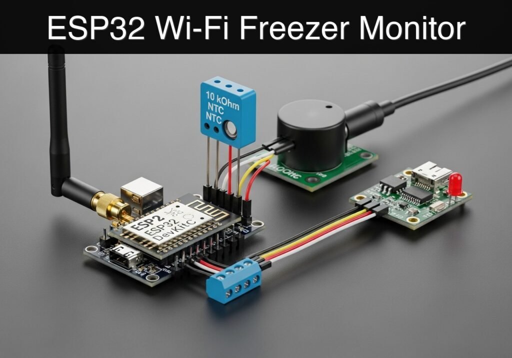
case-device-block-diagram, What you’ll build: A Wi-Fi-enabled freezer temperature monitoring system that reads an analog NTC thermistor, triggers a local audible and visual alarm when temperatures exceed a safe threshold (e.g., > -10°C), and serves real-time data to a local web dashboard with <1s latency. Audience: IoT hobbyists, electronics students, and prototype engineers; Level: Intermediate Architecture/flow: NTC Thermistor → Microcontroller ADC → Threshold Logic (GPIO Buzzer/LED) → Wi-Fi Access Point/Station → Local Web UI. High-level view: what enters the system, what each block processes, and what comes out. Conceptual flow: local configuration, BLE advertising and phone-side reading. Conceptual summary of the tools used to check the published ESP32 project. Before publication, this case passed the Prometeo automated validation gate with status PASS. For this ESP32 DevKitC profile, the project was checked as a PlatformIO project: the validator extracted This validation confirms syntax and tool compatibility for the published code, but it does not replace physical testing on your exact ESP32 DevKitC board, wiring, power supply and local WiFi environment. This project is a low-voltage educational prototype, not a certified food-safety alarm. Verify the pinout of your exact ESP32 DevKitC board and temperature sensor, keep all GPIO signals within 3.3 V limits, and do not connect the circuit to mains wiring or to the freezer’s internal power system. Use a reliable USB supply, protect wiring from moisture, and disconnect power before changing the setup. Before beginning this tutorial, ensure you have the following ready: To guarantee the code and wiring behave exactly as described, use the precise components listed below: The hardware setup requires carefully wiring the NTC thermistor in a voltage divider configuration, alongside the output peripherals. Important Engineering Note regarding ADC: We use GPIO34 for the thermistor. GPIO34 belongs to the ESP32’s The project relies on two files within the PlatformIO environment. Create a new PlatformIO project selecting the This configuration file defines the hardware target, framework, and serial monitor baud rate. This is the primary source code. Ensure you update the Public preview of the validated file. The complete source is shown to members and in PDF/Print. Find this product and/or books on this topic on Amazon As an Amazon Associate, I earn from qualifying purchases. If you buy through this link, you help keep this project running.
.prometeo-educational-note,
.prometeo-device-postcode-section,
.prometeo-device-section-card {
margin: 2.4rem 0;
padding: 1.45rem 1.55rem;
border: 1px solid rgba(148, 163, 184, 0.30);
border-radius: 14px;
background:
linear-gradient(135deg, rgba(30, 41, 59, 0.50), rgba(15, 23, 42, 0.18)),
rgba(17, 24, 39, 0.48);
box-shadow: 0 18px 48px rgba(0, 0, 0, 0.20);
}
.case-objective > h2:first-of-type,
.case-device-block-diagram > h2:first-of-type,
.prometeo-device-postcode-section > h2:first-of-type,
.prometeo-device-section-card > h2:first-of-type {
margin-top: 0;
}
.prometeo-device-section-card > :last-child,
.case-objective > :last-child,
.case-device-block-diagram > :last-child,
.prometeo-device-postcode-section > :last-child {
margin-bottom: 0;
}
.prometeo-device-section-card.prometeo-device-section-card-code {
border-left: 4px solid rgba(56, 189, 248, 0.86);
background:
linear-gradient(135deg, rgba(8, 47, 73, 0.42), rgba(15, 23, 42, 0.18)),
rgba(15, 23, 42, 0.58);
}
.prometeo-device-section-card.prometeo-device-section-card-compact {
padding: 1.2rem 1.35rem;
}
.prometeo-device-section-card pre,
.case-objective pre,
.case-device-block-diagram pre,
.prometeo-device-postcode-section pre {
max-width: 100%;
}
.prometeo-device-postcode-section .prometeo-device-flow-item {
background:
linear-gradient(135deg, rgba(15, 23, 42, 0.50), rgba(30, 41, 59, 0.28)),
rgba(15, 23, 42, 0.28);
}
@media print {
.case-objective,
.case-device-block-diagram,
.prometeo-educational-note,
.prometeo-device-postcode-section,
.prometeo-device-section-card {
background: #fff;
color: #111827;
box-shadow: none;
break-inside: avoid;
page-break-inside: avoid;
}
}
Objective and use case
Why it matters / Use cases
Expected outcome
Conceptual block diagram
Functional architecture
Validation path
Educational validation note
platformio.ini and src/main.cpp, created a temporary project and ran pio run against platform = espressif32, board = esp32dev and framework = arduino. It also checked article structure, copy/paste-safe ASCII command options, and unsupported stacks such as direct ESP-IDF or non-scoped ESP32 boards.Published validation evidence
Educational safety note
Prerequisites
* Software: Visual Studio Code with the PlatformIO IDE extension installed.
* Knowledge: Basic understanding of C++ programming, voltage dividers, and fundamental Wi-Fi networking concepts.
* Network: Access to a standard 2.4 GHz Wi-Fi network (ESP32 microcontrollers do not support 5 GHz networks).Materials
Component Specification / Exact Model Quantity Microcontroller ESP32 DevKitC (38-pin or 30-pin variant) 1 Temperature Sensor 10 kOhm NTC thermistor (B-value ~3950) 1 Fixed Resistor 10 kOhm (1/4 Watt, for the voltage divider) 1 Current Limiting Resistor 220 Ohm (1/4 Watt, for the LED) 1 Visual Indicator Status LED (Standard 5mm, Red preferred) 1 Audible Indicator Active buzzer (3.3V or 5V compatible) 1 Prototyping Breadboard and assorted jumper wires 1 set Power/Data Micro-USB data cable 1 Setup/Connection
ADC1 block. Do not use ADC2 pins (like GPIO4 or GPIO2) because ADC2 is utilized by the Wi-Fi driver and will fail to read analog voltages while the Wi-Fi radio is active.1. NTC Thermistor Voltage Divider
2. Active Buzzer
+ or the longer leg) of the active buzzer to GPIO26.3. Status LED
4. USB Driver Setup
Validated Code
esp32dev board and the Arduino framework. Replace the contents of the generated files with the code below.platformio.ini[env:esp32dev]
platform = espressif32
board = esp32dev
framework = arduino
monitor_speed = 115200
src/main.cppWIFI_SSID and WIFI_PASSWORD variables to match your local network credentials before compiling.#include <Arduino.h>
#include <WiFi.h>
#include <WebServer.h>
// ------------------------------------------------------------------
// Network Credentials
// ------------------------------------------------------------------
const char* WIFI_SSID = "LabNetwork";
const char* WIFI_PASSWORD = "LabPassword123";
// ------------------------------------------------------------------
// Pin Definitions
// ------------------------------------------------------------------
const int NTC_PIN = 34; // ADC1_CH6 - Safe to use with Wi-Fi
const int BUZZER_PIN = 26; // Output for active buzzer
const int LED_PIN = 27; // Output for status LED
// ------------------------------------------------------------------
// Thermistor & Steinhart-Hart Parameters
// ------------------------------------------------------------------
const float SERIES_RESISTOR = 10000.0; // 10k Ohm fixed resistor
const float NOMINAL_RESISTANCE = 10000.0; // 10k Ohm NTC at 25 degrees C
const float NOMINAL_TEMPERATURE = 25.0; // Nominal temperature in Celsius
const float B_COEFFICIENT = 3950.0; // Beta value of the thermistor
const float ALARM_THRESHOLD = -10.0; // Alarm triggers if temp rises above -10.0 C
// ------------------------------------------------------------------
// Global Variables
// ------------------------------------------------------------------
WebServer server(80);
float currentTemperature = 0.0;
bool isAlarmActive = false;
// Timing variables for non-blocking alarm
unsigned long previousMillis = 0;
const long blinkInterval = 500; // 500ms toggle rate for buzzer/LED
bool toggleState = false;
// ------------------------------------------------------------------
// Function Prototypes
// ------------------------------------------------------------------
void connectWiFi();
void handleRoot();
float readTemperature();
void handleAlarmLogic();
// ------------------------------------------------------------------
// Setup
// ------------------------------------------------------------------
void setup() {
Serial.begin(115200);
delay(1000); // Allow serial monitor to stabilize
// Initialize output pins
pinMode(BUZZER_PIN, OUTPUT);
pinMode(LED_PIN, OUTPUT);
digitalWrite(BUZZER_PIN, LOW);
digitalWrite(LED_PIN, LOW);
// Initialize ADC
analogReadResolution(12); // 12-bit ADC (0 - 4095)
Serial.println("\n--- Freezer Temperature Alarm System ---");
connectWiFi();
// Setup Web Server Routes
server.on("/", handleRoot);
server.begin();
Serial.println("Web server started.");
}
// ------------------------------------------------------------------
// Main Loop
// ------------------------------------------------------------------
void loop() {
server.handleClient(); // Listen for incoming HTTP requests
// Read temperature every cycle
currentTemperature = readTemperature();
// Evaluate and execute alarm logic
handleAlarmLogic();
// Small delay to stabilize ADC reads and prevent watchdog resets
delay(50);
}
// ...#include <Arduino.h>
#include <WiFi.h>
#include <WebServer.h>
// ------------------------------------------------------------------
// Network Credentials
// ------------------------------------------------------------------
const char* WIFI_SSID = "LabNetwork";
const char* WIFI_PASSWORD = "LabPassword123";
// ------------------------------------------------------------------
// Pin Definitions
// ------------------------------------------------------------------
const int NTC_PIN = 34; // ADC1_CH6 - Safe to use with Wi-Fi
const int BUZZER_PIN = 26; // Output for active buzzer
const int LED_PIN = 27; // Output for status LED
// ------------------------------------------------------------------
// Thermistor & Steinhart-Hart Parameters
// ------------------------------------------------------------------
const float SERIES_RESISTOR = 10000.0; // 10k Ohm fixed resistor
const float NOMINAL_RESISTANCE = 10000.0; // 10k Ohm NTC at 25 degrees C
const float NOMINAL_TEMPERATURE = 25.0; // Nominal temperature in Celsius
const float B_COEFFICIENT = 3950.0; // Beta value of the thermistor
const float ALARM_THRESHOLD = -10.0; // Alarm triggers if temp rises above -10.0 C
// ------------------------------------------------------------------
// Global Variables
// ------------------------------------------------------------------
WebServer server(80);
float currentTemperature = 0.0;
bool isAlarmActive = false;
// Timing variables for non-blocking alarm
unsigned long previousMillis = 0;
const long blinkInterval = 500; // 500ms toggle rate for buzzer/LED
bool toggleState = false;
// ------------------------------------------------------------------
// Function Prototypes
// ------------------------------------------------------------------
void connectWiFi();
void handleRoot();
float readTemperature();
void handleAlarmLogic();
// ------------------------------------------------------------------
// Setup
// ------------------------------------------------------------------
void setup() {
Serial.begin(115200);
delay(1000); // Allow serial monitor to stabilize
// Initialize output pins
pinMode(BUZZER_PIN, OUTPUT);
pinMode(LED_PIN, OUTPUT);
digitalWrite(BUZZER_PIN, LOW);
digitalWrite(LED_PIN, LOW);
// Initialize ADC
analogReadResolution(12); // 12-bit ADC (0 - 4095)
Serial.println("\n--- Freezer Temperature Alarm System ---");
connectWiFi();
// Setup Web Server Routes
server.on("/", handleRoot);
server.begin();
Serial.println("Web server started.");
}
// ------------------------------------------------------------------
// Main Loop
// ------------------------------------------------------------------
void loop() {
server.handleClient(); // Listen for incoming HTTP requests
// Read temperature every cycle
currentTemperature = readTemperature();
// Evaluate and execute alarm logic
handleAlarmLogic();
// Small delay to stabilize ADC reads and prevent watchdog resets
delay(50);
}
// ------------------------------------------------------------------
// Functions
// ------------------------------------------------------------------

void connectWiFi() {
    Serial.print("Connecting to Wi-Fi: ");
    Serial.println(WIFI_SSID);

    WiFi.mode(WIFI_STA);
    WiFi.begin(WIFI_SSID, WIFI_PASSWORD);

    while (WiFi.status() != WL_CONNECTED) {
        delay(500);
        Serial.print(".");
    }

    Serial.println("\nWi-Fi Connected!");
    Serial.print("IP Address: ");
    Serial.println(WiFi.localIP());
}

float readTemperature() {
    // Read the analog value (0-4095)
    int adcValue = analogRead(NTC_PIN);

    // Prevent division by zero if pin is shorted to Ground or 3.3V
    if (adcValue == 0) return -99.0;
if (adcValue >= 4095) return 99.0;
// Calculate NTC Resistance
// Based on Voltage Divider: Vout = Vcc * (R_NTC / (R_NTC + R_SERIES))
// Derives to: R_NTC = R_SERIES * (ADC / (4095 - ADC))
float ntcResistance = SERIES_RESISTOR * ((float)adcValue / (4095.0 - (float)adcValue));
// Apply Steinhart-Hart equation
float steinhart;
steinhart = ntcResistance / NOMINAL_RESISTANCE; // (R/Ro)
steinhart = log(steinhart); // ln(R/Ro)
steinhart /= B_COEFFICIENT; // 1/B * ln(R/Ro)
steinhart += 1.0 / (NOMINAL_TEMPERATURE + 273.15); // + (1/To)
steinhart = 1.0 / steinhart; // Invert
steinhart -= 273.15; // Convert Kelvin to Celsius
return steinhart;
}
void handleAlarmLogic() {
if (currentTemperature > ALARM_THRESHOLD) {
isAlarmActive = true;
// Non-blocking toggle for LED and Buzzer
unsigned long currentMillis = millis();
if (currentMillis - previousMillis >= blinkInterval) {
previousMillis = currentMillis;
toggleState = !toggleState;
digitalWrite(LED_PIN, toggleState ? HIGH : LOW);
digitalWrite(BUZZER_PIN, toggleState ? HIGH : LOW);
}
} else {
isAlarmActive = false;
// Ensure outputs are turned off when temperature is safe
digitalWrite(LED_PIN, LOW);
digitalWrite(BUZZER_PIN, LOW);
toggleState = false;
}
}
void handleRoot() {
// Construct a simple, auto-refreshing HTML dashboard
String html = "<!DOCTYPE html><html><head>";
html += "<meta name='viewport' content='width=device-width, initial-scale=1.0'>";
html += "<meta http-equiv='refresh' content='5'>"; // Auto-refresh every 5 seconds
html += "<style>";
html += "body { font-family: Arial, sans-serif; text-align: center; margin-top: 50px; }";
html += ".temp { font-size: 3em; font-weight: bold; }";
html += ".status-ok { color: green; font-size: 2em; }";
html += ".status-alarm { color: red; font-size: 2em; font-weight: bold; animation: blinker 1s linear infinite; }";
html += "@keyframes blinker { 50% { opacity: 0; } }";
html += "</style></head><body>";
html += "<h1>Freezer Monitor Dashboard</h1>";
html += "<div class='temp'>" + String(currentTemperature, 1) + " °C</div>";
if (isAlarmActive) {
html += "<div class='status-alarm'>WARNING: TEMPERATURE HIGH</div>";
} else {
html += "<div class='status-ok'>STATUS: NORMAL</div>";
}
html += "</body></html>";
// Send the response to the client
server.send(200, "text/html", html);
}


Quick Quiz

Telecommunications Electronics Engineer and Computer Engineer (official degrees in Spain).

