
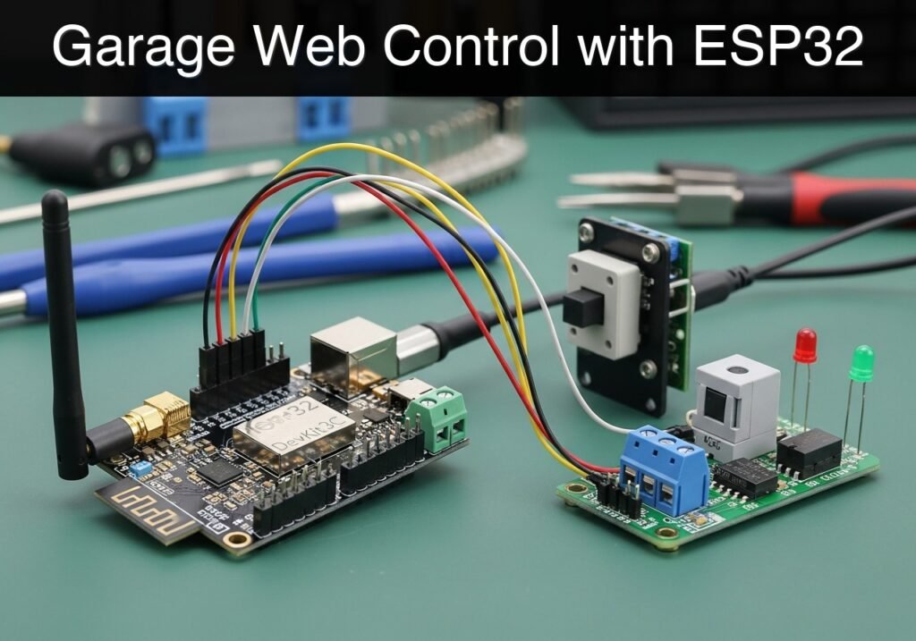
case-device-block-diagram, What you’ll build: You will build a standalone ESP32 web server that monitors a garage door’s physical state using a magnetic reed switch and securely actuates a relay to open or close it. This educational prototype provides a localized, cloud-free web interface for remote access control. Audience: IoT hobbyists and smart home developers; Level: Intermediate Architecture/flow: Web Browser → HTTP GET/POST (Local Wi-Fi) → ESP32 Web Server → GPIO Read (Reed Switch) / GPIO Write (5V Relay) → Garage Door Opener High-level view: what enters the system, what each block processes, and what comes out. Conceptual flow: local configuration, BLE advertising and phone-side reading. Conceptual summary of the tools used to check the published ESP32 project. Before publication, this case passed the Prometeo automated validation gate with status PASS. For this ESP32 DevKitC profile, the project was checked as a PlatformIO project: the validator extracted This validation confirms syntax and tool compatibility for the published code, but it does not replace physical testing on your exact ESP32 DevKitC board, wiring, power supply and local WiFi environment. This project is a low-voltage educational prototype for learning how to read a door state and drive a local output, not a certified garage-door opener or real access-control product. Test first with an LED or dummy load, connect the relay only to an isolated low-voltage dry-contact input on the opener, and never to mains, motors, or power wiring. Keep the door’s original limit switches, photocells, and physical safety protections in place. Before beginning this tutorial, ensure you have the following: For this practical case, you must use exactly the following device model and components: The hardware setup requires mapping the ESP32 GPIO pins to the respective components. The ESP32 operates at 3.3V logic, but most standard single-channel relay modules require 5V for the relay coil while accepting a 3.3V logic signal on their input pin. The ESP32 DevKitC provides a The project uses PlatformIO. Create a new project and replace the default configuration and source files with the code provided below. The code includes an embedded HTML, CSS, and JavaScript string. The JavaScript uses the modern This file configures the build environment, specifying the board, framework, and serial monitor speed. This is the primary source file containing the WiFi logic, the web server routing, and the GPIO hardware control. Update the Public preview of the validated file. The complete source is shown to members and in PDF/Print. Use the PlatformIO Core CLI to compile and upload the firmware. Open the terminal within VS Code and ensure you are in the root directory of your project. To ensure the prototype functions correctly and safely, perform the following grouped checkpoints. Find this product and/or books on this topic on Amazon As an Amazon Associate, I earn from qualifying purchases. If you buy through this link, you help keep this project running.
.prometeo-educational-note,
.prometeo-device-postcode-section,
.prometeo-device-section-card {
margin: 2.4rem 0;
padding: 1.45rem 1.55rem;
border: 1px solid rgba(148, 163, 184, 0.30);
border-radius: 14px;
background:
linear-gradient(135deg, rgba(30, 41, 59, 0.50), rgba(15, 23, 42, 0.18)),
rgba(17, 24, 39, 0.48);
box-shadow: 0 18px 48px rgba(0, 0, 0, 0.20);
}
.case-objective > h2:first-of-type,
.case-device-block-diagram > h2:first-of-type,
.prometeo-device-postcode-section > h2:first-of-type,
.prometeo-device-section-card > h2:first-of-type {
margin-top: 0;
}
.prometeo-device-section-card > :last-child,
.case-objective > :last-child,
.case-device-block-diagram > :last-child,
.prometeo-device-postcode-section > :last-child {
margin-bottom: 0;
}
.prometeo-device-section-card.prometeo-device-section-card-code {
border-left: 4px solid rgba(56, 189, 248, 0.86);
background:
linear-gradient(135deg, rgba(8, 47, 73, 0.42), rgba(15, 23, 42, 0.18)),
rgba(15, 23, 42, 0.58);
}
.prometeo-device-section-card.prometeo-device-section-card-compact {
padding: 1.2rem 1.35rem;
}
.prometeo-device-section-card pre,
.case-objective pre,
.case-device-block-diagram pre,
.prometeo-device-postcode-section pre {
max-width: 100%;
}
.prometeo-device-postcode-section .prometeo-device-flow-item {
background:
linear-gradient(135deg, rgba(15, 23, 42, 0.50), rgba(30, 41, 59, 0.28)),
rgba(15, 23, 42, 0.28);
}
@media print {
.case-objective,
.case-device-block-diagram,
.prometeo-educational-note,
.prometeo-device-postcode-section,
.prometeo-device-section-card {
background: #fff;
color: #111827;
box-shadow: none;
break-inside: avoid;
page-break-inside: avoid;
}
}
Objective and use case
Why it matters / Use cases
Expected outcome
Conceptual block diagram
Functional architecture
Validation path
Educational validation note
platformio.ini and src/main.cpp, created a temporary project and ran pio run against platform = espressif32, board = esp32dev and framework = arduino. It also checked article structure, copy/paste-safe ASCII command options, and unsupported stacks such as direct ESP-IDF or non-scoped ESP32 boards.Published validation evidence
Educational safety note
Prerequisites
* A computer running Windows, macOS, or Linux.
* Visual Studio Code (VS Code) installed.
* The PlatformIO IDE extension installed in VS Code.
* A micro-USB or USB-C cable that supports both power and data transfer.
* A local 2.4GHz WiFi network (ESP32 microcontrollers do not support 5GHz networks).Materials
* Microcontroller: ESP32 DevKitC (standard 38-pin or 30-pin version, featuring the ESP-WROOM-32 module).
* Sensor: Magnetic reed switch (standard normally-open door/window sensor with two wire leads).
* Actuator: 5V Relay module (1-channel, with built-in optoisolator and transistor driver).
* Prototyping: Standard solderless breadboard and assorted male-to-male and female-to-male jumper wires.Setup/Connection
5V (or VIN) pin that passes through the USB voltage, which we use to power the relay coil.Wiring Table
Component Component Pin / Wire ESP32 DevKitC Pin Notes Relay Module VCC / DC+ 5V / VIN Powers the relay coil (requires USB power). Relay Module GND / DC- GND Common ground. Relay Module IN / Signal GPIO 5 3.3V logic signal to trigger the relay. Relay Module NO & COM terminals Target Device Connects to the garage opener wall-button terminals. Reed Switch Wire 1 GPIO 18 Polarity does not matter. Reed Switch Wire 2 GND Uses ESP32 internal pull-up resistor. Connection Instructions
5V pin, GND to the ground rail, and the IN pin to GPIO 5.GND pin.Validated Code
fetch API to poll the ESP32 for the door status every 2 seconds, ensuring the web page reflects the physical reality of the door without requiring manual browser refreshes.platformio.ini[env:esp32dev]
platform = espressif32
board = esp32dev
framework = arduino
monitor_speed = 115200
src/main.cppWIFI_SSID and WIFI_PASSWORD macros to match your testing router.#include <Arduino.h>
#include <WiFi.h>
#include <WebServer.h>
// --- Configuration ---
#define WIFI_SSID "LabNetwork"
#define WIFI_PASSWORD "LabPassword123"
// --- GPIO Pin Definitions ---
const int RELAY_PIN = 5;
const int REED_SWITCH_PIN = 18;
// --- Web Server Initialization ---
// Initialize the web server on standard HTTP port 80
WebServer server(80);
// --- HTML/CSS/JS Payload ---
// Using a raw string literal to embed the frontend code cleanly
const char index_html[] PROGMEM = R"rawliteral(
<!DOCTYPE html>
<html lang="en">
<head>
<meta charset="UTF-8">
<meta name="viewport" content="width=device-width, initial-scale=1.0">
<title>Garage Door Web Monitor</title>
<style>
body {
font-family: 'Segoe UI', Tahoma, Geneva, Verdana, sans-serif;
background-color: #f4f4f9;
color: #333;
text-align: center;
padding: 50px 20px;
}
.container {
background: white;
padding: 30px;
border-radius: 10px;
box-shadow: 0 4px 8px rgba(0,0,0,0.1);
max-width: 400px;
margin: auto;
}
h1 { font-size: 1.5em; margin-bottom: 20px; }
.status {
font-size: 2em;
font-weight: bold;
margin: 20px 0;
padding: 10px;
border-radius: 5px;
}
.closed { background-color: #d4edda; color: #155724; border: 1px solid #c3e6cb; }
.open { background-color: #f8d7da; color: #721c24; border: 1px solid #f5c6cb; }
button {
background-color: #007bff;
color: white;
border: none;
padding: 15px 30px;
font-size: 1.2em;
border-radius: 5px;
cursor: pointer;
transition: background-color 0.3s;
}
button:hover { background-color: #0056b3; }
button:active { background-color: #004085; }
</style>
</head>
<body>
<div class="container">
<h1>Garage Door Monitor</h1>
<div id="door-status" class="status closed">Loading...</div>
<button onclick="triggerRelay()">Toggle Door</button>
</div>
<script>
// Function to fetch the current door status
function fetchStatus() {
fetch('/status')
.then(response => response.json())
.then(data => {
const statusDiv = document.getElementById('door-status');
if (data.state === "Closed") {
statusDiv.innerText = "CLOSED";
statusDiv.className = "status closed";
} else {
statusDiv.innerText = "OPEN";
statusDiv.className = "status open";
}
})
.catch(error => console.error('Error fetching status:', error));
}
// Function to trigger the relay via POST request
function triggerRelay() {
fetch('/trigger', { method: 'POST' })
.then(response => {
if(response.ok) {
console.log("Relay triggered successfully.");
// Immediately fetch status to reflect potential changes
setTimeout(fetchStatus, 1000);
}
})
.catch(error => console.error('Error triggering relay:', error));
}
// ...#include <Arduino.h>
#include <WiFi.h>
#include <WebServer.h>
// --- Configuration ---
#define WIFI_SSID "LabNetwork"
#define WIFI_PASSWORD "LabPassword123"
// --- GPIO Pin Definitions ---
const int RELAY_PIN = 5;
const int REED_SWITCH_PIN = 18;
// --- Web Server Initialization ---
// Initialize the web server on standard HTTP port 80
WebServer server(80);
// --- HTML/CSS/JS Payload ---
// Using a raw string literal to embed the frontend code cleanly
const char index_html[] PROGMEM = R"rawliteral(
<!DOCTYPE html>
<html lang="en">
<head>
<meta charset="UTF-8">
<meta name="viewport" content="width=device-width, initial-scale=1.0">
<title>Garage Door Web Monitor</title>
<style>
body {
font-family: 'Segoe UI', Tahoma, Geneva, Verdana, sans-serif;
background-color: #f4f4f9;
color: #333;
text-align: center;
padding: 50px 20px;
}
.container {
background: white;
padding: 30px;
border-radius: 10px;
box-shadow: 0 4px 8px rgba(0,0,0,0.1);
max-width: 400px;
margin: auto;
}
h1 { font-size: 1.5em; margin-bottom: 20px; }
.status {
font-size: 2em;
font-weight: bold;
margin: 20px 0;
padding: 10px;
border-radius: 5px;
}
.closed { background-color: #d4edda; color: #155724; border: 1px solid #c3e6cb; }
.open { background-color: #f8d7da; color: #721c24; border: 1px solid #f5c6cb; }
button {
background-color: #007bff;
color: white;
border: none;
padding: 15px 30px;
font-size: 1.2em;
border-radius: 5px;
cursor: pointer;
transition: background-color 0.3s;
}
button:hover { background-color: #0056b3; }
button:active { background-color: #004085; }
</style>
</head>
<body>
<div class="container">
<h1>Garage Door Monitor</h1>
<div id="door-status" class="status closed">Loading...</div>
<button onclick="triggerRelay()">Toggle Door</button>
</div>
<script>
// Function to fetch the current door status
function fetchStatus() {
fetch('/status')
.then(response => response.json())
.then(data => {
const statusDiv = document.getElementById('door-status');
if (data.state === "Closed") {
statusDiv.innerText = "CLOSED";
statusDiv.className = "status closed";
} else {
statusDiv.innerText = "OPEN";
statusDiv.className = "status open";
}
})
.catch(error => console.error('Error fetching status:', error));
}
// Function to trigger the relay via POST request
function triggerRelay() {
fetch('/trigger', { method: 'POST' })
.then(response => {
if(response.ok) {
console.log("Relay triggered successfully.");
// Immediately fetch status to reflect potential changes
setTimeout(fetchStatus, 1000);
}
})
.catch(error => console.error('Error triggering relay:', error));
}
        // Poll the ESP32 every 2 seconds for status updates
        setInterval(fetchStatus, 2000);

        // Fetch initial status on load
        window.onload = fetchStatus;
    </script>
</body>
</html>
)rawliteral";

// --- Route Handlers ---

// Serve the main HTML page
void handleRoot() {
    server.send(200, "text/html", index_html);
}

// Return the current state of the reed switch as JSON
void handleStatus() {
    // Read the reed switch.
    // LOW means the magnet is present (door closed).
    // HIGH means the magnet is away (door open).
    int sensorValue = digitalRead(REED_SWITCH_PIN);
    String state = (sensorValue == LOW) ? "Closed" : "Open";

    String jsonResponse = "{\"state\": \"" + state + "\"}";
    server.send(200, "application/json", jsonResponse);
}
// Pulse the relay to simulate a button press
void handleTrigger() {
if (server.method() != HTTP_POST) {
server.send(405, "text/plain", "Method Not Allowed");
return;
}
// Most relays are Active HIGH. If yours is Active LOW, invert these states.
digitalWrite(RELAY_PIN, HIGH);
delay(500); // Hold the relay closed for 500ms
digitalWrite(RELAY_PIN, LOW);
server.send(200, "text/plain", "Triggered");
}
// Handle 404 Not Found
void handleNotFound() {
server.send(404, "text/plain", "404: Not Found");
}
// --- Main Setup and Loop ---
void setup() {
// Initialize Serial Monitor
Serial.begin(115200);
delay(100);
Serial.println("\n--- Garage Door Web Monitor ---");
// Initialize GPIOs
pinMode(RELAY_PIN, OUTPUT);
// Ensure relay starts in the OFF state immediately
digitalWrite(RELAY_PIN, LOW);
// Use internal pull-up for the reed switch
pinMode(REED_SWITCH_PIN, INPUT_PULLUP);
// Connect to WiFi
Serial.print("Connecting to WiFi: ");
Serial.println(WIFI_SSID);
WiFi.begin(WIFI_SSID, WIFI_PASSWORD);
// Wait for connection
while (WiFi.status() != WL_CONNECTED) {
delay(500);
Serial.print(".");
}
Serial.println("\nWiFi connected successfully.");
Serial.print("IP Address: ");
Serial.println(WiFi.localIP());
// Configure Web Server Routes
server.on("/", HTTP_GET, handleRoot);
server.on("/status", HTTP_GET, handleStatus);
server.on("/trigger", HTTP_POST, handleTrigger);
server.onNotFound(handleNotFound);
// Start the server
server.begin();
Serial.println("HTTP server started.");
}
void loop() {
// Listen for incoming client requests
server.handleClient();
// Small delay to yield to the ESP32's underlying WiFi/OS tasks
delay(2);
}
Build/Flash/Run commands
Command Table
Action Command Initialize Project (if needed) pio project init --board esp32devBuild Firmware pio runUpload to ESP32 pio run --target uploadOpen Serial Monitor pio device monitorWorkflow
platformio.ini and src/main.cpp with the Validated Code provided above.pio run --target upload in the terminal to compile the code and flash it to the microcontroller.pio device monitor to view the serial output. Note the IP address printed once the WiFi connects.Step‑by‑step Validation
192.168.1.50).Troubleshooting
Symptom Likely cause Fix Serial Monitor prints continuous dots; never connects. Incorrect WiFi credentials or out of range. Verify WIFI_SSID and WIFI_PASSWORD exactly match your 2.4GHz network. Ensure the ESP32 is within range of the router.Web page loads, but status stays on “Loading…”. JavaScript fetch error or browser blocking local requests. Check the browser’s developer console (F12) for CORS or network errors. Ensure you are accessing via http://, not https://.Relay clicks immediately on boot and stays triggered. Relay module is “Active LOW” instead of “Active HIGH”. Change digitalWrite(RELAY_PIN, LOW) to HIGH in setup(), and swap HIGH/LOW in the handleTrigger() function.Door status randomly flips between Open and Closed. Floating pin or loose wire on the reed switch. Ensure the reed switch is firmly connected to GPIO 18 and GND. Verify pinMode is strictly set to INPUT_PULLUP.Relay LED lights up, but there is no audible “click”. Insufficient power to the relay coil. Ensure the relay VCC is connected to the ESP32 5V (VIN) pin, not the 3.3V pin. Ensure the USB port provides sufficient current (500mA+).


Quick Quiz

Telecommunications Electronics Engineer and Computer Engineer (official degrees in Spain).

