
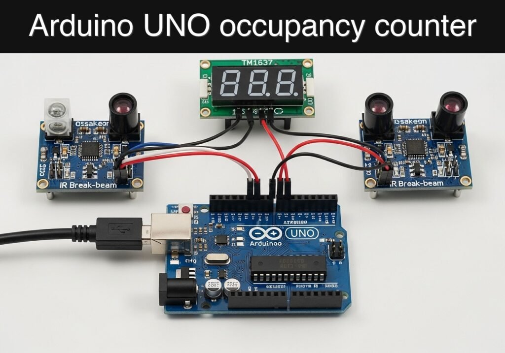
Objective and use case
What you’ll build: A doorway visitor counter using an Arduino UNO R3, two IR break-beam sensors, and a TM1637 4-digit display. The system detects entry vs. exit by timing which beam breaks first, then updates the live occupancy count on the display with near-instant feedback, typically under 100–200 ms per event.
Why it matters / Use cases
- Classroom or lab occupancy tracking: estimate how many people are inside a room by mounting the beams across a narrow doorway or small door-frame model.
- Workshop access monitoring: show a quick live count at a makerspace entrance so students can judge whether the room is crowded before entering.
- Pop-up event booth counting: measure approximate foot traffic by counting entries and exits during school demos or exhibitions.
- Storage or equipment room supervision: monitor whether a restricted area is occupied without cameras, image capture, or networked video processing.
- Embedded systems practice: learn direction detection, debounce handling, sensor spacing, timing windows, and simple real-time display updates on an 8-bit microcontroller using minimal power and 0% GPU.
Expected outcome
- The TM1637 4-digit display shows the current occupancy count and updates immediately after each validated pass.
- The system increases the count when beam A then beam B is triggered, and decreases it when beam B then beam A is triggered.
- False triggers are reduced through debounce logic and a short direction-detection window, for example 300–800 ms depending on doorway width and walking speed.
- The prototype runs fully on the Arduino UNO at simple loop-level responsiveness, with event handling effectively in real time and no camera, no FPS pipeline, and no GPU load.
Audience: students, makers, and beginner embedded developers building practical sensor-based prototypes; Level: beginner to intermediate
Architecture/flow: IR sensor 1 and IR sensor 2 feed digital signals to the Arduino UNO, which compares trigger order and timing, validates the movement direction, updates an internal occupancy variable, and sends the new count to the TM1637 display.
Educational validation note
Before publication, this case passed the Prometeo automated validation gate with status PASS. The validator checked the code blocks, article structure, copy/paste-safe commands and consistency with the supported device catalog.
Published validation evidence
- Automatic result: PASS.
- Parsed structure: 3 sections, 3 tables and 4 code blocks detected before publication.
- Checked code: 1 Arduino/arduino-cli compile, 1 Bash/copy-paste checks.
- Supported catalog: the article text was checked against Prometeo’s validation-capable device profiles, and unsupported stacks block publication.
- Report findings: no blocking findings.
This validation confirms syntax and tool compatibility for the published material, but it does not replace physical testing on your exact hardware, wiring and runtime environment.
Educational safety note
This prototype is an educational occupancy counter, not a security-certified access-control device and not a safety system. It should not be used where miscounts could create hazards, legal compliance issues, emergency egress decisions, or critical operational consequences.
Specific limits to keep in mind:
- It is designed for low-voltage USB-powered educational use only.
- It should not be used to control door locks, gates, industrial machinery, or emergency systems.
- It is best suited to one person at a time through a narrow path; closely grouped people can confuse the direction logic.
- Direct sunlight or strong IR sources can reduce reliability.
- The displayed count is an estimate based on beam interruptions, not a guaranteed headcount.
- Secure all wiring and mounts so nothing can fall into the walking path or create a trip hazard.
Prerequisites
Before starting, you should have:
- A computer with USB access to the Arduino UNO
- Arduino CLI installed and available in your terminal
- Basic understanding of:
- digital input pins
millis()timing- Arduino sketch upload
- simple breadboard wiring
- A narrow test path where you can move a hand or object through the two IR beams in sequence
Recommended preparation:
- Install Arduino CLI.
- Confirm the UNO appears as a serial port on your system.
- Keep the two break-beam sensor pairs physically separated by a small distance such as 8 cm to 20 cm.
- Test in indoor lighting first before moving to a brighter environment.
Materials
Use the exact device family and model requested:
- Arduino UNO R3 (ATmega328P)
- Two IR break-beam sensors
- Each sensor set normally includes an IR emitter and an IR receiver
- TM1637 4-digit display
- Breadboard
- Jumper wires
- USB cable for Arduino UNO
- Optional:
- Cardboard, foam board, or 3D-printed mini doorway frame
- Double-sided tape or zip ties for sensor alignment
Suggested material roles
| Part | Role in the project | Notes |
|---|---|---|
| Arduino UNO R3 (ATmega328P) | Main controller | Runs counting logic and updates display |
| IR break-beam sensor pair A | First beam position | Detects one side of crossing |
| IR break-beam sensor pair B | Second beam position | Detects second side of crossing |
| TM1637 4-digit display | Local occupancy display | Shows 0 to 9999 count |
| Breadboard and jumpers | Prototyping interconnect | Keep sensor wiring short and tidy |
Setup/Connection
This project uses:
- two digital inputs for the IR receivers
- two digital outputs for the TM1637 display
- 5 V and GND rails for all modules
Pin assignment
Use the following Arduino pins:
- IR receiver A output -> D2
- IR receiver B output -> D3
- TM1637 CLK -> D4
- TM1637 DIO -> D5
Power connections:
- TM1637 VCC -> 5V
- TM1637 GND -> GND
- IR receiver A VCC -> 5V
- IR receiver A GND -> GND
- IR receiver B VCC -> 5V
- IR receiver B GND -> GND
- IR emitter A -> 5V and GND as required by its module
- IR emitter B -> 5V and GND as required by its module
Important wiring notes
- Receiver outputs only go to Arduino input pins.
- Do not connect sensor outputs directly to the display.
- Most break-beam receivers behave as active-low outputs.
- That means:
- beam intact -> input reads HIGH
- beam broken -> input reads LOW
- The sketch below assumes this common behavior.
- Sensor alignment matters more than code.
- Place emitter and receiver directly facing each other.
- Confirm each beam changes state reliably before testing direction logic.
- Beam spacing affects accuracy.
- Start with 10 cm to 15 cm between beam A and beam B.
- Too close: direction can become ambiguous.
- Too far: a person may pause between beams and trigger timeouts.
- Use a narrow passage.
- This works best when only one person passes at a time.
Practical mounting idea
Build a simple educational prototype doorway:
- Make a cardboard arch or rectangular frame.
- Mount beam A on one side and its receiver opposite.
- Mount beam B parallel to A, slightly behind it along the walking direction.
- Label the outside side of the frame and the inside side.
- Define:
- A then B = entering
- B then A = leaving
That makes the object immediately useful as a room-entry counter.
Validated Code
dual_ir_beam_visitor_counter.ino
Public preview of the validated file. The complete source is shown to members and in PDF/Print.
/*
  dual_ir_beam_visitor_counter.ino

  Target:
    Arduino UNO R3 (ATmega328P)

  Hardware:
    - 2x IR break-beam receivers on D2 and D3
    - TM1637 4-digit display on D4 (CLK) and D5 (DIO)

  Behavior:
    - Beam A then Beam B => ENTRY => count++
    - Beam B then Beam A => EXIT  => count-- (not below zero)
    - Serial output logs events for validation
    - Display shows occupancy count from 0 to 9999

  Notes:
    - Assumes receiver outputs are active-low:
        beam clear   -> HIGH
        beam broken  -> LOW
    - Uses INPUT_PULLUP for stable idle state
*/

#include <Arduino.h>

// -----------------------------
// Pin configuration
// -----------------------------
const uint8_t PIN_BEAM_A = 2;
const uint8_t PIN_BEAM_B = 3;
const uint8_t PIN_TM1637_CLK = 4;
const uint8_t PIN_TM1637_DIO = 5;

// -----------------------------
// Behavior configuration
// -----------------------------
const bool SENSOR_ACTIVE_LOW = true;
const unsigned long DEBOUNCE_MS = 20;
const unsigned long SEQUENCE_TIMEOUT_MS = 1200;
const unsigned long COOLDOWN_MS = 300;

// Display brightness: 0 to 7
const uint8_t DISPLAY_BRIGHTNESS = 4;

// -----------------------------
// Simple TM1637 driver
// -----------------------------
class SimpleTM1637 {
public:
  SimpleTM1637(uint8_t clkPin, uint8_t dioPin)
    : _clk(clkPin), _dio(dioPin) {}

  void begin() {
    pinMode(_clk, OUTPUT);
    pinMode(_dio, OUTPUT);
    digitalWrite(_clk, HIGH);
    digitalWrite(_dio, HIGH);
    setBrightness(DISPLAY_BRIGHTNESS, true);
  }

  void setBrightness(uint8_t brightness, bool on = true) {
    if (brightness > 7) brightness = 7;
    _brightnessCmd = 0x88 | (on ? brightness : 0);
  }

  void showNumber(int value) {
    if (value < 0) value = 0;
    if (value > 9999) value = 9999;

    uint8_t digits[4];
    digits[0] = encodeDigit((value / 1000) % 10);
    digits[1] = encodeDigit((value / 100) % 10);
    digits[2] = encodeDigit((value / 10) % 10);
    digits[3] = encodeDigit(value % 10);

    // Leading blanking except for zero itself
    if (value < 1000) digits[0] = 0x00;
    if (value < 100)  digits[1] = 0x00;
    if (value < 10)   digits[2] = 0x00;
    if (value == 0) {
      digits[0] = 0x00;
      digits[1] = 0x00;
      digits[2] = 0x00;
      digits[3] = encodeDigit(0);
    }

    setSegments(digits);
  }

  void showDashes() {
    uint8_t dash = 0x40;
    uint8_t digits[4] = {dash, dash, dash, dash};
    setSegments(digits);
  }

private:
  uint8_t _clk;
  uint8_t _dio;
  uint8_t _brightnessCmd = 0x8F;

  uint8_t encodeDigit(uint8_t digit) {
    static const uint8_t map[10] = {
      0x3F, // 0
      0x06, // 1
      0x5B, // 2
      0x4F, // 3
      0x66, // 4
      0x6D, // 5
      0x7D, // 6
      0x07, // 7
      0x7F, // 8
      0x6F  // 9
    };
    if (digit < 10) return map[digit];
    return 0x00;
  }

  void bitDelay() {
    delayMicroseconds(5);
  }

  void start() {
    pinMode(_dio, OUTPUT);
    digitalWrite(_dio, HIGH);
    digitalWrite(_clk, HIGH);
    bitDelay();
    digitalWrite(_dio, LOW);
  }

  void stop() {
    pinMode(_dio, OUTPUT);
    digitalWrite(_clk, LOW);
    bitDelay();
    digitalWrite(_dio, LOW);
    bitDelay();
    digitalWrite(_clk, HIGH);
    bitDelay();
    digitalWrite(_dio, HIGH);
  }

  bool writeByte(uint8_t b) {
    for (uint8_t i = 0; i < 8; i++) {
      digitalWrite(_clk, LOW);
      bitDelay();

      if (b & 0x01) {
        digitalWrite(_dio, HIGH);
      } else {
        digitalWrite(_dio, LOW);
      }

      bitDelay();
      digitalWrite(_clk, HIGH);
      bitDelay();
      b >>= 1;
    }

    // ACK
    digitalWrite(_clk, LOW);
    pinMode(_dio, INPUT_PULLUP);
    bitDelay();
    digitalWrite(_clk, HIGH);
    bitDelay();
    bool ack = (digitalRead(_dio) == LOW);
    digitalWrite(_clk, LOW);
    pinMode(_dio, OUTPUT);
    return ack;
  }

  void setSegments(uint8_t segments[4]) {
    start();
    writeByte(0x40); // auto increment mode
    stop();

    start();
    writeByte(0xC0); // address 0
    for (uint8_t i = 0; i < 4; i++) {
      writeByte(segments[i]);
    }
// .../*
dual_ir_beam_visitor_counter.ino
Target:
Arduino UNO R3 (ATmega328P)
Hardware:
- 2x IR break-beam receivers on D2 and D3
- TM1637 4-digit display on D4 (CLK) and D5 (DIO)
Behavior:
- Beam A then Beam B => ENTRY => count++
- Beam B then Beam A => EXIT => count-- (not below zero)
- Serial output logs events for validation
- Display shows occupancy count from 0 to 9999
Notes:
- Assumes receiver outputs are active-low:
beam clear -> HIGH
beam broken -> LOW
- Uses INPUT_PULLUP for stable idle state
*/
#include <Arduino.h>
// -----------------------------
// Pin configuration
// -----------------------------
const uint8_t PIN_BEAM_A = 2;
const uint8_t PIN_BEAM_B = 3;
const uint8_t PIN_TM1637_CLK = 4;
const uint8_t PIN_TM1637_DIO = 5;
// -----------------------------
// Behavior configuration
// -----------------------------
const bool SENSOR_ACTIVE_LOW = true;
const unsigned long DEBOUNCE_MS = 20;
const unsigned long SEQUENCE_TIMEOUT_MS = 1200;
const unsigned long COOLDOWN_MS = 300;
// Display brightness: 0 to 7
const uint8_t DISPLAY_BRIGHTNESS = 4;
// -----------------------------
// Simple TM1637 driver
// -----------------------------
class SimpleTM1637 {
public:
SimpleTM1637(uint8_t clkPin, uint8_t dioPin)
: _clk(clkPin), _dio(dioPin) {}
void begin() {
pinMode(_clk, OUTPUT);
pinMode(_dio, OUTPUT);
digitalWrite(_clk, HIGH);
digitalWrite(_dio, HIGH);
setBrightness(DISPLAY_BRIGHTNESS, true);
}
void setBrightness(uint8_t brightness, bool on = true) {
if (brightness > 7) brightness = 7;
_brightnessCmd = 0x88 | (on ? brightness : 0);
}
void showNumber(int value) {
if (value < 0) value = 0;
if (value > 9999) value = 9999;
uint8_t digits[4];
digits[0] = encodeDigit((value / 1000) % 10);
digits[1] = encodeDigit((value / 100) % 10);
digits[2] = encodeDigit((value / 10) % 10);
digits[3] = encodeDigit(value % 10);
// Leading blanking except for zero itself
if (value < 1000) digits[0] = 0x00;
if (value < 100) digits[1] = 0x00;
if (value < 10) digits[2] = 0x00;
if (value == 0) {
digits[0] = 0x00;
digits[1] = 0x00;
digits[2] = 0x00;
digits[3] = encodeDigit(0);
}
setSegments(digits);
}
void showDashes() {
uint8_t dash = 0x40;
uint8_t digits[4] = {dash, dash, dash, dash};
setSegments(digits);
}
private:
uint8_t _clk;
uint8_t _dio;
uint8_t _brightnessCmd = 0x8F;
uint8_t encodeDigit(uint8_t digit) {
static const uint8_t map[10] = {
0x3F, // 0
0x06, // 1
0x5B, // 2
0x4F, // 3
0x66, // 4
0x6D, // 5
0x7D, // 6
0x07, // 7
0x7F, // 8
0x6F // 9
};
if (digit < 10) return map[digit];
return 0x00;
}
void bitDelay() {
delayMicroseconds(5);
}
void start() {
pinMode(_dio, OUTPUT);
digitalWrite(_dio, HIGH);
digitalWrite(_clk, HIGH);
bitDelay();
digitalWrite(_dio, LOW);
}
void stop() {
pinMode(_dio, OUTPUT);
digitalWrite(_clk, LOW);
bitDelay();
digitalWrite(_dio, LOW);
bitDelay();
digitalWrite(_clk, HIGH);
bitDelay();
digitalWrite(_dio, HIGH);
}
bool writeByte(uint8_t b) {
for (uint8_t i = 0; i < 8; i++) {
digitalWrite(_clk, LOW);
bitDelay();
if (b & 0x01) {
digitalWrite(_dio, HIGH);
} else {
digitalWrite(_dio, LOW);
}
bitDelay();
digitalWrite(_clk, HIGH);
bitDelay();
b >>= 1;
}
// ACK
digitalWrite(_clk, LOW);
pinMode(_dio, INPUT_PULLUP);
bitDelay();
digitalWrite(_clk, HIGH);
bitDelay();
bool ack = (digitalRead(_dio) == LOW);
digitalWrite(_clk, LOW);
pinMode(_dio, OUTPUT);
return ack;
}
void setSegments(uint8_t segments[4]) {
start();
writeByte(0x40); // auto increment mode
stop();
start();
writeByte(0xC0); // address 0
for (uint8_t i = 0; i < 4; i++) {
writeByte(segments[i]);
}
    stop();

    start();
    writeByte(_brightnessCmd);
    stop();
  }
};

SimpleTM1637 display(PIN_TM1637_CLK, PIN_TM1637_DIO);

// -----------------------------
// Debounced sensor input
// -----------------------------
struct DebouncedInput {
  uint8_t pin;
  bool stableState;
  bool lastRawState;
  unsigned long lastChangeMs;

  void begin(uint8_t p) {
    pin = p;
    pinMode(pin, INPUT_PULLUP);
    stableState = digitalRead(pin);
    lastRawState = stableState;
    lastChangeMs = millis();
  }

  void update() {
bool raw = digitalRead(pin);
unsigned long now = millis();
if (raw != lastRawState) {
lastRawState = raw;
lastChangeMs = now;
}
if ((now - lastChangeMs) >= DEBOUNCE_MS) {
stableState = lastRawState;
}
}
bool isBroken() const {
if (SENSOR_ACTIVE_LOW) {
return stableState == LOW;
} else {
return stableState == HIGH;
}
}
};
DebouncedInput beamA;
DebouncedInput beamB;
// -----------------------------
// Direction state machine
// -----------------------------
enum CountState {
IDLE,
WAIT_B_AFTER_A,
WAIT_A_AFTER_B,
COOLDOWN
};
CountState countState = IDLE;
unsigned long stateStartMs = 0;
unsigned int occupancyCount = 0;
bool prevBrokenA = false;
bool prevBrokenB = false;
void enterState(CountState newState) {
countState = newState;
stateStartMs = millis();
}
void logState(const char* msg) {
Serial.print("[");
Serial.print(millis());
Serial.print(" ms] ");
Serial.println(msg);
}
void handleEvents() {
bool brokenA = beamA.isBroken();
bool brokenB = beamB.isBroken();
bool risingBreakA = (!prevBrokenA && brokenA);
bool risingBreakB = (!prevBrokenB && brokenB);
unsigned long now = millis();
switch (countState) {
case IDLE:
if (risingBreakA && !brokenB) {
enterState(WAIT_B_AFTER_A);
logState("Sequence start: A first");
} else if (risingBreakB && !brokenA) {
enterState(WAIT_A_AFTER_B);
logState("Sequence start: B first");
}
break;
case WAIT_B_AFTER_A:
if ((now - stateStartMs) > SEQUENCE_TIMEOUT_MS) {
enterState(IDLE);
logState("TIMEOUT after A first");
} else if (risingBreakB) {
if (occupancyCount < 9999) {
occupancyCount++;
}
display.showNumber(occupancyCount);
Serial.print("[");
Serial.print(now);
Serial.print(" ms] ENTRY, count=");
Serial.println(occupancyCount);
enterState(COOLDOWN);
}
break;
case WAIT_A_AFTER_B:
if ((now - stateStartMs) > SEQUENCE_TIMEOUT_MS) {
enterState(IDLE);
logState("TIMEOUT after B first");
} else if (risingBreakA) {
if (occupancyCount > 0) {
occupancyCount--;
}
display.showNumber(occupancyCount);
Serial.print("[");
Serial.print(now);
Serial.print(" ms] EXIT, count=");
Serial.println(occupancyCount);
enterState(COOLDOWN);
}
break;
case COOLDOWN:
// Wait until both beams are clear or cooldown expires
if ((!brokenA && !brokenB) && ((now - stateStartMs) > COOLDOWN_MS)) {
enterState(IDLE);
} else if ((now - stateStartMs) > (COOLDOWN_MS + 1000)) {
enterState(IDLE);
}
break;
}
prevBrokenA = brokenA;
prevBrokenB = brokenB;
}
void setup() {
Serial.begin(115200);
beamA.begin(PIN_BEAM_A);
beamB.begin(PIN_BEAM_B);
display.begin();
display.showNumber(occupancyCount);
prevBrokenA = beamA.isBroken();
prevBrokenB = beamB.isBroken();
logState("Dual IR beam visitor counter started");
Serial.println("Rule: A then B = ENTRY, B then A = EXIT");
Serial.println("Initial count=0");
}
void loop() {
beamA.update();
beamB.update();
handleEvents();
static unsigned long lastRefreshMs = 0;
unsigned long now = millis();
if ((now - lastRefreshMs) >= 100) {
display.showNumber(occupancyCount);
lastRefreshMs = now;
}
}
Optional serial monitor reference output
This is not code you upload, but it helps you know what normal behavior looks like:
[12 ms] Dual IR beam visitor counter started
Rule: A then B = ENTRY, B then A = EXIT
Initial count=0
[5021 ms] Sequence start: A first
[5288 ms] ENTRY, count=1
[9140 ms] Sequence start: B first
[9412 ms] EXIT, count=0
[12040 ms] Sequence start: A first
[13270 ms] TIMEOUT after A first
Build/Flash/Run commands
Use Arduino CLI exactly as required.
Command table
| Task | Command |
|---|---|
| Update board index | arduino-cli core update-index |
| Install AVR core | arduino-cli core install arduino:avr |
| Compile sketch | arduino-cli compile --fqbn arduino:avr:uno dual_ir_beam_visitor_counter |
| Upload sketch | arduino-cli upload --fqbn arduino:avr:uno --port <PORT> dual_ir_beam_visitor_counter |
| Open serial monitor | arduino-cli monitor --port <PORT> --config 115200 |
Short workflow
- Create the sketch folder:
bash

mkdir -p dual_ir_beam_visitor_counter - Save the
.inofile as:
text

dual_ir_beam_visitor_counter/dual_ir_beam_visitor_counter.ino - Run the command table from the folder that contains the sketch directory.
- Replace
<PORT>with your actual device port, for example: - Linux:
/dev/ttyACM0 - macOS:
/dev/cu.usbmodem14101 - Windows:
COM4 - After upload, open the serial monitor and walk a hand or object through the beams.
Step-by-step Validation
Use these checkpoints in order. They are intentionally practical and easy to reproduce on a workbench.
1. Power and display check
Action
– Connect the UNO by USB.
– Upload the sketch.
– Observe the TM1637 display immediately after reset.
Expected observation
– The display shows 0.
– The serial monitor prints startup text.
Pass condition
– The display is stable and readable.
– The serial monitor shows the start banner without random resets.
2. Single-sensor alignment check
Action
– Keep the other beam untouched.
– Break only beam A with your finger or a card.
– Then clear it.
– Repeat with only beam B.
Expected observation
– You may see sequence-start messages in Serial when one beam is broken first.
– If you do not complete the second beam, a timeout message should appear after about 1.2 seconds.
Pass condition
– Each beam can be individually interrupted in a repeatable way.
– No permanent stuck state remains after clearing the beam.
3. Entry direction check
Action
– Move an object through the path in the A then B direction.
– Do this slowly and clearly for 5 passes, one pass at a time.
Expected observation
– For each clean crossing, Serial prints:
– Sequence start: A first
– then ENTRY, count=<n>
– The display increments by 1 each time.
Pass condition
– The displayed count increases exactly once per clean A-then-B crossing.
4. Exit direction check
Action
– Now move through the path in the B then A direction.
– Perform 5 clean passes.
Expected observation
– For each clean crossing, Serial prints:
– Sequence start: B first
– then EXIT, count=<n>
– The display decreases by 1 each time, but not below zero.
Pass condition
– The display decreases correctly and never shows a negative number.
5. Timeout and false-trigger check
Action
– Break beam A, hold for longer than the timeout, then remove your hand without crossing beam B.
– Repeat with beam B only.
– Test with quick accidental taps near only one beam.
Expected observation
– Serial prints timeout messages.
– The display count does not change.
Pass condition
– Incomplete crossings do not change occupancy.
6. Repeated use check
Action
– Perform 10 mixed crossings in known order, for example:
– Entry, Entry, Exit, Entry, Exit, Exit, Entry, Entry, Entry, Exit
– Manually compute the expected final count.
Expected observation
– The display matches your manual total.
– Serial logs correspond to the crossing order.
Pass condition
– Final displayed occupancy equals the expected value after the full test sequence.
Troubleshooting
| Symptom | Likely cause | Fix |
|---|---|---|
| Display stays blank | TM1637 VCC/GND reversed, wrong CLK/DIO pins, bad jumper | Recheck power and confirm CLK -> D4, DIO -> D5 |
| Display powers but never changes from 0 | Sensor outputs not connected, sensors misaligned, wrong sensor logic | Confirm receiver outputs go to D2 and D3; realign emitters/receivers; verify active-low behavior |
| Count increases when leaving and decreases when entering | Beam labels A and B reversed physically | Swap the physical beam positions or swap D2 and D3 connections |
| One crossing produces two counts | Beams too close, reflections, person lingering, insufficient cooldown | Increase spacing to 10-15 cm, narrow the path, reduce reflections, keep one-at-a-time passage |
| Random counts with nobody crossing | Ambient IR interference, loose wires, unstable sensor modules | Move away from direct sunlight, tighten connections, improve mounting |
| Serial monitor shows timeouts frequently | Beams too far apart or movement too slow | Reduce beam spacing or increase SEQUENCE_TIMEOUT_MS slightly |
| Count never decreases below 0 but exits seem ignored | Starting count is already zero | Perform a few entries first, then test exits |
| Upload fails | Wrong port or missing Arduino core | Re-run arduino-cli core update-index, arduino-cli core install arduino:avr, and verify the correct port |
Improvements
Better physical reliability
- Build a more rigid doorway frame from acrylic, wood, or 3D-printed brackets.
- Add side shields around the IR receivers to reduce ambient light interference.
- Use a narrower passage so only one person can cross at a time.
Better software behavior
- Store the count in EEPROM periodically so it survives power cycling.
- Add a long-press reset button to clear the count when the room is known to be empty.
- Tune:
DEBOUNCE_MSSEQUENCE_TIMEOUT_MSCOOLDOWN_MS
to match your doorway and walking speed.
Better system usability
- Add a buzzer or LED feedback on each valid entry/exit event.
- Add a serial command such as
resetorset 25for manual calibration after setup. - Add a second display mode that alternates between occupancy and total entries for the day.
Final Checklist
- [ ] I used exactly Arduino UNO R3 (ATmega328P) + two IR break-beam sensors + TM1637 4-digit display.
- [ ] Beam A receiver output is connected to D2.
- [ ] Beam B receiver output is connected to D3.
- [ ] TM1637 CLK -> D4 and DIO -> D5.
- [ ] All modules share 5V and GND correctly.
- [ ] I saved the sketch as
dual_ir_beam_visitor_counter/dual_ir_beam_visitor_counter.ino. - [ ] I ran:
- [ ]
arduino-cli core update-index - [ ]
arduino-cli core install arduino:avr - [ ]
arduino-cli compile --fqbn arduino:avr:uno dual_ir_beam_visitor_counter - [ ]
arduino-cli upload --fqbn arduino:avr:uno --port <PORT> dual_ir_beam_visitor_counter - [ ] The display shows
0at startup. - [ ] A then B increments the displayed count.
- [ ] B then A decrements the displayed count.
- [ ] Incomplete crossings produce timeout logs but do not change the count.
- [ ] The prototype is mounted in a narrow, realistic doorway path for practical use.
Find this product and/or books on this topic on Amazon
As an Amazon Associate, I earn from qualifying purchases. If you buy through this link, you help keep this project running.
Quick Quiz

Telecommunications Electronics Engineer and Computer Engineer (official degrees in Spain).

