
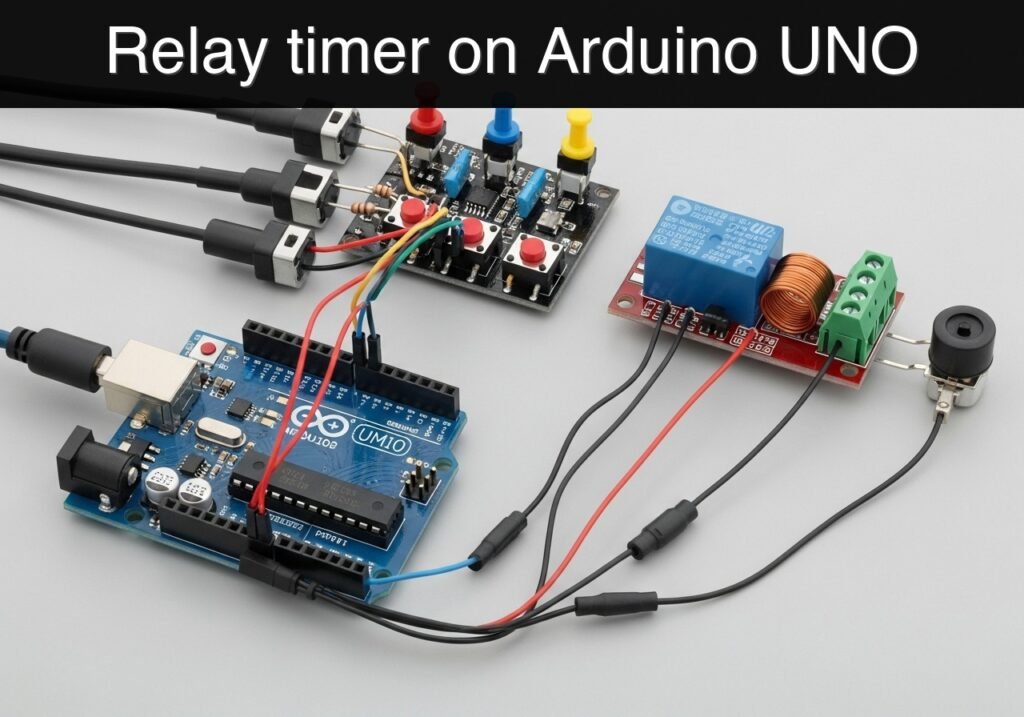
Objective and use case
What you’ll build: A standalone workshop countdown relay timer using an Arduino UNO R3, pushbuttons, a 1-channel relay module, and a piezo buzzer. Users can set a duration, start a non-blocking countdown with millis(), keep a 5 V or 12 V load energized through the relay while time remains, and trigger an audible alert when the timer reaches 0.
Why it matters / Use cases
- Automatically shut off small bench loads such as a 5 V fan, miniature pump, or 12 V test lamp after a fixed 30 s to 10 min work cycle.
- Improve repeatability for workshop tasks like adhesive warming, PCB fume extraction, cleaner runs, or jig activation where consistent timing matters more than manual estimation.
- Teach core embedded skills in one build: button reading, debounce timing in the 10–50 ms range, relay control, buzzer feedback, and finite-state logic without using
delay(). - Run fully standalone after upload, with near-instant button response under typical loop times of a few milliseconds and no PC connection required.
Expected outcome
- A timer that lets the user increase or decrease duration with pushbuttons, then start or stop the countdown reliably.
- A relay output that stays active for the programmed interval and switches off immediately when time expires or the cycle is canceled.
- A buzzer pattern at completion, for example 2–3 short beeps over 1–2 s, to clearly signal the end of the timed run.
- A responsive low-load Arduino implementation: no meaningful GPU usage, very low CPU demand on the ATmega328P, and sub-10 ms control latency for normal button and output events.
Audience: Arduino beginners, makers, students, and electronics workshop users; Level: beginner to lower-intermediate
Architecture/flow: Pushbuttons feed the UNO digital inputs; the sketch debounces presses, updates the selected time, and tracks countdown state with millis(); the UNO drives the relay input to energize the external load during the active window and toggles the piezo buzzer when the countdown completes.
Educational validation note
Before publication, this case passed the Prometeo automated validation gate with status PASS. The validator checked the code blocks, article structure, copy/paste-safe commands and consistency with the supported device catalog.
Published validation evidence
- Automatic result: PASS.
- Parsed structure: 3 sections, 3 tables and 2 code blocks detected before publication.
- Checked code: 1 Arduino/arduino-cli compile, 1 Bash/copy-paste checks.
- Supported catalog: the article text was checked against Prometeo’s validation-capable device profiles, and unsupported stacks block publication.
- Report findings: no blocking findings.
This validation confirms syntax and tool compatibility for the published material, but it does not replace physical testing on your exact hardware, wiring and runtime environment.
Educational safety note
This prototype is intended for education and bench-level experimentation. Its limits are important:
- Do not use this beginner build to switch household mains voltage unless you are trained and your lab explicitly permits it.
- Relay modules can expose dangerous voltages on their contact terminals.
- For classroom validation, use a low-voltage DC load only.
- The Arduino side and relay contact side are different electrical domains. Treat the relay contact wiring carefully even if the control side is only 5 V.
- Do not use this timer to control:
- safety-critical tools
- unattended heating systems
- medical devices
- vehicle systems
- high-power machinery
- If you later connect motors, solenoids, or other inductive loads, additional protection and proper power design may be required.
- Keep wiring insulated, stable, and strain-relieved. Loose relay wiring can create unreliable switching or hazardous shorts.
- The piezo buzzer is only an alert aid. It is not guaranteed to be heard in a noisy workshop.
- This tutorial demonstrates a useful educational prototype, not a certified product.
Prerequisites
Before starting, make sure you have:
- Basic familiarity with the Arduino IDE concept, even though this tutorial uses Arduino CLI
- A USB cable for the Arduino UNO R3
- A computer with:
- Arduino CLI installed
- A serial terminal available, or the Arduino IDE Serial Monitor if preferred
- Basic understanding of:
- Digital inputs with pull-up resistors
- Digital outputs
- Safe use of relay modules
- A low-voltage load for testing the relay output
- Recommended: a small DC lamp, LED load module, low-voltage fan, or small DC motor supply line through the relay contacts
- Do not start with household mains loads in a beginner lab
Materials
Use the exact platform below.
- Arduino UNO R3 (ATmega328P)
- 3 pushbuttons
Suggested labels: - ADD
- START/PAUSE
- CANCEL/RESET
- 1-channel relay module
- 5 V coil/module version compatible with Arduino logic
- Prefer a module with transistor driver and input indicator LED
- Piezo buzzer
- Passive or active buzzer; this tutorial assumes a simple piezo buzzer that can be driven from a digital pin
- Breadboard
- Jumper wires
- USB cable for Arduino UNO R3
- Optional but recommended:
- Small low-voltage DC lamp or fan as the relay-switched test load
- External low-voltage supply for that test load if needed by the load
Setup/Connection
This project uses the Arduino’s internal pull-up resistors for all pushbuttons. That means each button is wired between the input pin and GND. When not pressed, the input reads HIGH. When pressed, it reads LOW.
Pin assignment
| Function | Arduino pin | Wiring details |
|---|---|---|
| ADD button | D2 | One side of pushbutton to D2, other side to GND |
| START/PAUSE button | D3 | One side of pushbutton to D3, other side to GND |
| CANCEL/RESET button | D4 | One side of pushbutton to D4, other side to GND |
| Relay input | D8 | Relay module IN to D8 |
| Buzzer | D9 | Buzzer signal to D9, buzzer ground to GND |
| Relay VCC | 5V | Relay module VCC to Arduino 5V |
| Relay GND | GND | Relay module GND to Arduino GND |
| Buzzer GND | GND | Buzzer ground to Arduino GND |
| USB power/data | USB | Arduino to computer |
Connection notes
- Pushbuttons
- Connect one terminal of each button to the assigned digital pin.
- Connect the other terminal of each button to GND.
No external resistors are needed because the sketch enables
INPUT_PULLUP.Relay module
- Connect:
VCC->5VGND->GNDIN->D8
- Many relay modules are active-low, meaning the relay turns on when the Arduino pin outputs
LOW. The code below is written for a common active-low relay module and includes one constant you can change if your module is active-high.
Piezo buzzer
- Connect the positive/signal pin to
D9. - Connect the negative pin to
GND. For many small piezo buzzers, direct connection is acceptable for a basic educational prototype.
Relay contact side
- The relay contact terminals are separate from the Arduino side.
- For a timer-controlled output, use the relay’s COM and NO terminals if you want the load to turn on only while timing is active.
- Keep your first test simple:
- Use a low-voltage load
- Use a known safe supply
- Verify the relay switches correctly before connecting anything more complex
Suggested operating behavior
- ADD button: increases preset time by 1 minute, from 1 to 60 minutes, then wraps back to 1
- START/PAUSE button: starts the timer if idle; pauses/resumes if already running
- CANCEL/RESET button: stops the timer and returns to the current preset value
- Buzzer feedback:
- Short beep on valid button actions
- Distinct multi-beep pattern when time completes
Validated Code
workshop_countdown_relay_timer.ino
Public preview of the validated file. The complete source is shown to members and in PDF/Print.
/*
  workshop_countdown_relay_timer.ino

  Device model:
  Arduino UNO R3 (ATmega328P) + pushbuttons + 1-channel relay module + piezo buzzer

  Project goal:
  workshop-countdown-relay-timer

  Behavior:
  - ADD button: increase preset time by 1 minute (1..60, wrap around)
  - START/PAUSE button:
      * if idle -> start countdown
      * if running -> pause
      * if paused -> resume
  - CANCEL/RESET button:
      * stop countdown
      * relay off
      * restore remaining time to preset
  - Relay is active while countdown is running
  - Buzzer gives short feedback on actions and a completion pattern at the end

  Notes:
  - Buttons use INPUT_PULLUP, so pressed = LOW
  - Relay modules are often active-low; set RELAY_ACTIVE_LOW accordingly
*/

const byte PIN_BTN_ADD = 2;
const byte PIN_BTN_START = 3;
const byte PIN_BTN_CANCEL = 4;
const byte PIN_RELAY = 8;
const byte PIN_BUZZER = 9;

const bool RELAY_ACTIVE_LOW = true;

const unsigned long DEBOUNCE_MS = 35;
const unsigned long STATUS_PRINT_MS = 1000;
const unsigned long MINUTES_MAX = 60;
const unsigned long DEFAULT_PRESET_MIN = 5;

enum TimerState {
  IDLE,
  RUNNING,
  PAUSED,
  FINISHED
};

TimerState timerState = IDLE;

unsigned long presetMinutes = DEFAULT_PRESET_MIN;
unsigned long remainingMs = DEFAULT_PRESET_MIN * 60UL * 1000UL;
unsigned long lastTickMs = 0;
unsigned long lastStatusPrintMs = 0;

struct Button {
  byte pin;
  bool stableState;
  bool lastReading;
  unsigned long lastChangeMs;
};

Button btnAdd    = {PIN_BTN_ADD, HIGH, HIGH, 0};
Button btnStart  = {PIN_BTN_START, HIGH, HIGH, 0};
Button btnCancel = {PIN_BTN_CANCEL, HIGH, HIGH, 0};

void setRelay(bool on) {
  if (RELAY_ACTIVE_LOW) {
    digitalWrite(PIN_RELAY, on ? LOW : HIGH);
  } else {
    digitalWrite(PIN_RELAY, on ? HIGH : LOW);
  }
}

void beep(unsigned int frequency, unsigned long durationMs) {
  tone(PIN_BUZZER, frequency, durationMs);
}

void shortBeep() {
  beep(2200, 70);
}

void doubleBeep() {
  beep(2000, 60);
  delay(100);
  beep(2600, 80);
}

void finishBeepPattern() {
  for (int i = 0; i < 3; i++) {
    beep(1800, 120);
    delay(180);
  }
  beep(2600, 350);
  delay(400);
}

bool buttonPressedEvent(Button &button) {
  bool reading = digitalRead(button.pin);

  if (reading != button.lastReading) {
    button.lastChangeMs = millis();
    button.lastReading = reading;
  }

  if ((millis() - button.lastChangeMs) > DEBOUNCE_MS) {
    if (reading != button.stableState) {
      button.stableState = reading;

      // Because INPUT_PULLUP is used, LOW means pressed
      if (button.stableState == LOW) {
        return true;
      }
    }
  }

  return false;
}

void printHelp() {
  Serial.println(F("Workshop Countdown Relay Timer"));
  Serial.println(F("Buttons:"));
  Serial.println(F("  ADD         -> +1 minute preset (1..60)"));
  Serial.println(F("  START/PAUSE -> start, pause, resume"));
  Serial.println(F("  CANCEL      -> stop and reset to preset"));
  Serial.println();
}

void printStateLine() {
  unsigned long totalSeconds = remainingMs / 1000UL;
  unsigned int minutesPart = totalSeconds / 60UL;
  unsigned int secondsPart = totalSeconds % 60UL;

  Serial.print(F("Preset="));
  Serial.print(presetMinutes);
  Serial.print(F(" min, Remaining="));
  if (minutesPart < 10) Serial.print('0');
  Serial.print(minutesPart);
  Serial.print(':');
  if (secondsPart < 10) Serial.print('0');
  Serial.print(secondsPart);
  Serial.print(F(", State="));

  switch (timerState) {
    case IDLE: Serial.print(F("IDLE")); break;
    case RUNNING: Serial.print(F("RUNNING")); break;
    case PAUSED: Serial.print(F("PAUSED")); break;
    case FINISHED: Serial.print(F("FINISHED")); break;
  }
// .../*
workshop_countdown_relay_timer.ino
Device model:
Arduino UNO R3 (ATmega328P) + pushbuttons + 1-channel relay module + piezo buzzer
Project goal:
workshop-countdown-relay-timer
Behavior:
- ADD button: increase preset time by 1 minute (1..60, wrap around)
- START/PAUSE button:
* if idle -> start countdown
* if running -> pause
* if paused -> resume
- CANCEL/RESET button:
* stop countdown
* relay off
* restore remaining time to preset
- Relay is active while countdown is running
- Buzzer gives short feedback on actions and a completion pattern at the end
Notes:
- Buttons use INPUT_PULLUP, so pressed = LOW
- Relay modules are often active-low; set RELAY_ACTIVE_LOW accordingly
*/
const byte PIN_BTN_ADD = 2;
const byte PIN_BTN_START = 3;
const byte PIN_BTN_CANCEL = 4;
const byte PIN_RELAY = 8;
const byte PIN_BUZZER = 9;
const bool RELAY_ACTIVE_LOW = true;
const unsigned long DEBOUNCE_MS = 35;
const unsigned long STATUS_PRINT_MS = 1000;
const unsigned long MINUTES_MAX = 60;
const unsigned long DEFAULT_PRESET_MIN = 5;
enum TimerState {
IDLE,
RUNNING,
PAUSED,
FINISHED
};
TimerState timerState = IDLE;
unsigned long presetMinutes = DEFAULT_PRESET_MIN;
unsigned long remainingMs = DEFAULT_PRESET_MIN * 60UL * 1000UL;
unsigned long lastTickMs = 0;
unsigned long lastStatusPrintMs = 0;
struct Button {
byte pin;
bool stableState;
bool lastReading;
unsigned long lastChangeMs;
};
Button btnAdd = {PIN_BTN_ADD, HIGH, HIGH, 0};
Button btnStart = {PIN_BTN_START, HIGH, HIGH, 0};
Button btnCancel = {PIN_BTN_CANCEL, HIGH, HIGH, 0};
void setRelay(bool on) {
if (RELAY_ACTIVE_LOW) {
digitalWrite(PIN_RELAY, on ? LOW : HIGH);
} else {
digitalWrite(PIN_RELAY, on ? HIGH : LOW);
}
}
void beep(unsigned int frequency, unsigned long durationMs) {
tone(PIN_BUZZER, frequency, durationMs);
}
void shortBeep() {
beep(2200, 70);
}
void doubleBeep() {
beep(2000, 60);
delay(100);
beep(2600, 80);
}
void finishBeepPattern() {
for (int i = 0; i < 3; i++) {
beep(1800, 120);
delay(180);
}
beep(2600, 350);
delay(400);
}
bool buttonPressedEvent(Button &button) {
bool reading = digitalRead(button.pin);
if (reading != button.lastReading) {
button.lastChangeMs = millis();
button.lastReading = reading;
}
if ((millis() - button.lastChangeMs) > DEBOUNCE_MS) {
if (reading != button.stableState) {
button.stableState = reading;
// Because INPUT_PULLUP is used, LOW means pressed
if (button.stableState == LOW) {
return true;
}
}
}
return false;
}
void printHelp() {
Serial.println(F("Workshop Countdown Relay Timer"));
Serial.println(F("Buttons:"));
Serial.println(F(" ADD -> +1 minute preset (1..60)"));
Serial.println(F(" START/PAUSE -> start, pause, resume"));
Serial.println(F(" CANCEL -> stop and reset to preset"));
Serial.println();
}
void printStateLine() {
unsigned long totalSeconds = remainingMs / 1000UL;
unsigned int minutesPart = totalSeconds / 60UL;
unsigned int secondsPart = totalSeconds % 60UL;
Serial.print(F("Preset="));
Serial.print(presetMinutes);
Serial.print(F(" min, Remaining="));
if (minutesPart < 10) Serial.print('0');
Serial.print(minutesPart);
Serial.print(':');
if (secondsPart < 10) Serial.print('0');
Serial.print(secondsPart);
Serial.print(F(", State="));
switch (timerState) {
case IDLE: Serial.print(F("IDLE")); break;
case RUNNING: Serial.print(F("RUNNING")); break;
case PAUSED: Serial.print(F("PAUSED")); break;
case FINISHED: Serial.print(F("FINISHED")); break;
}
  Serial.print(F(", Relay="));
  Serial.println((timerState == RUNNING) ? F("ON") : F("OFF"));
}

void resetToPreset() {
  remainingMs = presetMinutes * 60UL * 1000UL;
  lastTickMs = millis();
}

void handleAddButton() {
  // For simplicity in a basic project, allow preset changes only when not running
  if (timerState == RUNNING) {
    doubleBeep();
    Serial.println(F("ADD ignored while running. Pause or cancel first."));
    return;
  }

  presetMinutes++;
  if (presetMinutes > MINUTES_MAX) {
    presetMinutes = 1;
  }

  resetToPreset();

  if (timerState == FINISHED) {
    timerState = IDLE;
  }
shortBeep();
Serial.print(F("Preset changed to "));
Serial.print(presetMinutes);
Serial.println(F(" minute(s)."));
printStateLine();
}
void handleStartButton() {
if (timerState == IDLE || timerState == FINISHED) {
resetToPreset();
timerState = RUNNING;
setRelay(true);
lastTickMs = millis();
shortBeep();
Serial.println(F("Countdown started."));
printStateLine();
return;
}
if (timerState == RUNNING) {
timerState = PAUSED;
setRelay(false);
shortBeep();
Serial.println(F("Countdown paused."));
printStateLine();
return;
}
if (timerState == PAUSED) {
timerState = RUNNING;
setRelay(true);
lastTickMs = millis();
shortBeep();
Serial.println(F("Countdown resumed."));
printStateLine();
return;
}
}
void handleCancelButton() {
timerState = IDLE;
setRelay(false);
resetToPreset();
doubleBeep();
Serial.println(F("Countdown canceled and reset to preset."));
printStateLine();
}
void updateTimer() {
if (timerState != RUNNING) {
return;
}
unsigned long now = millis();
unsigned long elapsed = now - lastTickMs;
lastTickMs = now;
if (elapsed >= remainingMs) {
remainingMs = 0;
timerState = FINISHED;
setRelay(false);
Serial.println(F("Countdown complete. Relay turned OFF."));
printStateLine();
finishBeepPattern();
return;
}
remainingMs -= elapsed;
}
void setup() {
pinMode(PIN_BTN_ADD, INPUT_PULLUP);
pinMode(PIN_BTN_START, INPUT_PULLUP);
pinMode(PIN_BTN_CANCEL, INPUT_PULLUP);
pinMode(PIN_RELAY, OUTPUT);
pinMode(PIN_BUZZER, OUTPUT);
setRelay(false);
Serial.begin(9600);
delay(300);
printHelp();
resetToPreset();
printStateLine();
}
void loop() {
if (buttonPressedEvent(btnAdd)) {
handleAddButton();
}
if (buttonPressedEvent(btnStart)) {
handleStartButton();
}
if (buttonPressedEvent(btnCancel)) {
handleCancelButton();
}
updateTimer();
unsigned long now = millis();
if (now - lastStatusPrintMs >= STATUS_PRINT_MS) {
lastStatusPrintMs = now;
printStateLine();
}
}
What the code is doing
This sketch uses a state machine with four states:
IDLE– waiting for user inputRUNNING– countdown active, relay onPAUSED– countdown frozen, relay offFINISHED– countdown reached zero, relay off, buzzer alert completed
Important beginner-friendly design choices:
- No blocking countdown loop
The timer usesmillis()instead of a longdelay(), so button presses stay responsive. - Debounced buttons
Each button is filtered with a small debounce interval to reduce false triggers from contact bounce. - Preset and remaining time are separate
presetMinutesstores the chosen duration, whileremainingMstracks what is left during a run. - Serial status output
The Arduino prints regular updates, which makes troubleshooting much easier during validation.
Build/Flash/Run commands
Command table
| Purpose | Command |
|---|---|
| Update board index | arduino-cli core update-index |
| Install AVR core | arduino-cli core install arduino:avr |
| Compile sketch | arduino-cli compile --fqbn arduino:avr:uno workshop_countdown_relay_timer |
| Upload sketch | arduino-cli upload --fqbn arduino:avr:uno --port <PORT> workshop_countdown_relay_timer |
Example terminal session
arduino-cli core update-index
arduino-cli core install arduino:avr
arduino-cli compile --fqbn arduino:avr:uno workshop_countdown_relay_timer
arduino-cli upload --fqbn arduino:avr:uno --port <PORT> workshop_countdown_relay_timer
Short workflow
- Create a folder named
workshop_countdown_relay_timer. - Save the sketch as:
workshop_countdown_relay_timer/workshop_countdown_relay_timer.ino- Open a terminal in the parent directory of that folder.
- Run the compile command.
- Connect the Arduino UNO R3 by USB.
- Replace
<PORT>with your actual serial port and run the upload command. - Linux example:
/dev/ttyACM0 - Windows example:
COM4 - macOS example:
/dev/cu.usbmodem14101 - Open a serial monitor at 9600 baud to observe timer status.
Step-by-step Validation
Use these checkpoints in order. The goal is to validate the exact workshop-countdown-relay-timer behavior.
1. Power-up and idle status
Action
– Connect the Arduino by USB.
– Open the serial monitor at 9600 baud.
Expected observation
– You should see a startup banner like:
– Workshop Countdown Relay Timer
– You should also see a status line with:
– Preset=5 min
– State=IDLE
– Relay=OFF
Pass condition
– The relay is not energized at startup.
– The serial monitor shows the preset time and idle state without random characters.
2. Preset adjustment using the ADD button
Action
– Press the ADD button once.
– Then press it several more times.
Expected observation
– Each press increases the preset by 1 minute.
– The serial monitor reports:
– Preset changed to 6 minute(s).
– and updated state lines
– After 60 minutes, the next press wraps to 1 minute.
Pass condition
– One button press produces one preset change.
– No frequent double-counting occurs from switch bounce.
– The timer remains in IDLE and the relay stays off during preset adjustment.
3. Start countdown and confirm relay activation
Action
– Set a short test preset such as 1 minute.
– Press START/PAUSE once.
Expected observation
– Serial output says:
– Countdown started.
– State=RUNNING
– Relay=ON
– The relay module indicator LED, if present, should change state.
– Your connected low-voltage test load should turn on through the relay.
Pass condition
– Relay activates only when the timer enters RUNNING.
– The remaining time decreases once per second in the serial monitor.
4. Pause, resume, and cancel behavior
Action
– While running, press START/PAUSE again.
– Press it once more to resume.
– Then press CANCEL/RESET.
Expected observation
– On pause:
– State=PAUSED
– Relay=OFF
– On resume:
– State=RUNNING
– Relay=ON
– On cancel:
– Countdown canceled and reset to preset.
– State=IDLE
– Relay=OFF
Pass condition
– Pause stops the countdown without losing the remaining time.
– Resume continues from the paused remaining time.
– Cancel immediately turns off the relay and restores the full preset value.
5. End-of-countdown completion test
Action
– Set the preset to 1 minute and let it run to zero without pressing buttons.
Expected observation
– At completion:
– Serial output reports Countdown complete. Relay turned OFF.
– State changes to FINISHED
– The buzzer sounds a recognizable completion pattern
– The low-voltage test load turns off at the same moment the relay deactivates.
Pass condition
– Relay turns off automatically at timeout.
– Completion buzzer sounds once per countdown completion event.
– The system does not restart by itself.
Troubleshooting
| Symptom | Likely cause | Fix |
|---|---|---|
| Button press does nothing | Button wired to 5V instead of GND, wrong pin, poor breadboard contact | Verify each button goes between pin and GND, and matches D2/D3/D4 |
| Relay is always on | Relay module active-low behavior not matched, or wiring error | Check RELAY_ACTIVE_LOW; if needed change to false and re-upload |
| Relay clicks but load does not switch | COM/NO/NC contacts wired incorrectly | Use relay contact terminals correctly; for normal timed-on behavior use COM and NO |
| Buzzer silent | Buzzer polarity reversed, wrong pin, or incompatible buzzer type | Confirm buzzer is on D9 and GND; try another piezo buzzer |
| Serial monitor shows unreadable text | Wrong baud rate | Set serial monitor to 9600 baud |
| Timer resets unexpectedly | USB power unstable or load noise affecting supply | Use a stable USB cable, keep relay/load wiring tidy, and avoid powering noisy loads from the Arduino 5V rail |
| One press causes two actions | Switch bounce or loose connection | Re-seat wires, use better pushbuttons, keep button wiring short |
| Upload fails | Wrong port, missing board core, cable issue | Re-run core install, verify port, use a known data-capable USB cable |
Improvements
Usability upgrades
- Add a 4-digit 7-segment display or LCD to show remaining time without using the serial monitor.
- Add a long-press feature on the ADD button for faster time setting.
- Store the last preset in EEPROM so the timer remembers it after power loss.
Control and timing features
- Add a 10-second adjustment mode for short process timing.
- Add a post-run buzzer mute option so the timer can be used in quieter classrooms.
- Add a relay overrun mode, where a fan keeps running for an extra minute after a work cycle ends.
Electrical robustness
- Use a proper project enclosure with labeled buttons.
- Add screw terminals for the load side and strain relief for wires.
- If switching inductive DC loads, add the right suppression methods on the load side according to the module and load type.
Final Checklist
- [ ] I used Arduino UNO R3 (ATmega328P)
- [ ] I used 3 pushbuttons, 1-channel relay module, and piezo buzzer
- [ ] Buttons are wired from input pin to GND
- [ ] Relay module is connected to 5V, GND, and D8
- [ ] Buzzer is connected to D9 and GND
- [ ] I saved the file as
workshop_countdown_relay_timer/workshop_countdown_relay_timer.ino - [ ] I ran
arduino-cli core update-index - [ ] I ran
arduino-cli core install arduino:avr - [ ] I compiled with
arduino-cli compile --fqbn arduino:avr:uno workshop_countdown_relay_timer - [ ] I uploaded with
arduino-cli upload --fqbn arduino:avr:uno --port <PORT> workshop_countdown_relay_timer - [ ] Serial monitor at 9600 baud shows startup status
- [ ] ADD changes the preset time
- [ ] START begins countdown and turns relay on
- [ ] PAUSE turns relay off and preserves remaining time
- [ ] CANCEL stops the timer and restores the preset
- [ ] Countdown completion turns relay off and triggers the buzzer pattern
Find this product and/or books on this topic on Amazon
As an Amazon Associate, I earn from qualifying purchases. If you buy through this link, you help keep this project running.
Quick Quiz

Telecommunications Electronics Engineer and Computer Engineer (official degrees in Spain).

