
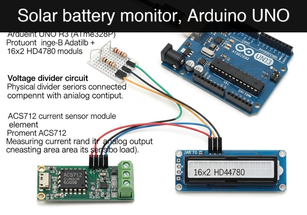
Objective and use case
What you’ll build: An Arduino-based solar battery monitor that reads 12 V battery voltage through a voltage divider, measures charge or load current with an ACS712 sensor, and displays both values on a 16×2 HD44780 LCD. The system gives near real-time local readings with a simple refresh around 2–5 updates/sec and typical display latency under 500 ms.
Why it matters / Use cases
- Confirm a small solar panel is actually charging by checking for positive current, for example +0.3 A to +1.8 A in direct sun on a shed, camping box, or classroom demo setup.
- Reduce battery damage by spotting low voltage early, such as a 12 V lead-acid battery dropping toward 11.8–12.0 V while powering LED lights, a router backup, or a small DC fan.
- Measure real load current by placing the ACS712 in series with a lamp, pump, or USB converter and verifying expected draw, such as 0.15 A for LEDs or 0.8 A for a small pump.
- Use it as a reusable bench monitor beside a charge controller or battery box for quick maintenance checks without needing a laptop, app, or cloud dashboard.
- Learn practical embedded measurement, including analog sensing, calibration, ADC scaling, and sensor noise handling in a low-power Arduino project.
Expected outcome
- A working LCD readout showing battery voltage and current continuously, for example “12.6 V” and “+0.42 A”.
- Voltage readings scaled from the divider and current readings interpreted from the ACS712 with basic calibration for more stable values.
- A compact monitor suitable for small 12 V solar experiments, with no meaningful GPU usage and no FPS dependency beyond the LCD refresh rate.
- A practical baseline you can extend with alarms, data logging, state-of-charge estimates, or charge/discharge direction indicators.
Audience: Arduino beginners, students, makers, and hobbyists working with small solar or battery projects; Level: Beginner to intermediate
Architecture/flow: Arduino reads battery voltage from a resistor divider and current from the ACS712 analog output, converts both ADC values into engineering units, then refreshes the 16×2 HD44780 LCD every 200–500 ms with live voltage/current status.
Educational validation note
Before publication, this case passed the Prometeo automated validation gate with status PASS. The validator checked the code blocks, article structure, copy/paste-safe commands and consistency with the supported device catalog.
Published validation evidence
- Automatic result: PASS.
- Parsed structure: 3 sections, 4 tables and 2 code blocks detected before publication.
- Checked code: 1 Arduino/arduino-cli compile, 1 Bash/copy-paste checks.
- Supported catalog: the article text was checked against Prometeo’s validation-capable device profiles, and unsupported stacks block publication.
- Report findings: no blocking findings.
This validation confirms syntax and tool compatibility for the published material, but it does not replace physical testing on your exact hardware, wiring and runtime environment.
Educational safety note
This is an educational low-voltage monitoring prototype, not a certified battery instrument.
Important limits and precautions:
- Work only on low-voltage DC educational setups.
- Do not connect the Arduino analog pin directly to a battery; always use the stated voltage divider.
- Do not use this tutorial directly on large solar arrays, high-current battery banks, vehicle electrical systems, or mains-connected equipment.
- The ACS712 module current path and terminal rating must match your actual current. Do not exceed the module rating.
- Batteries can deliver high fault current even at low voltage:
- avoid short circuits
- fuse the battery line if possible
- keep exposed conductors insulated
- If your solar system includes a charge controller, understand the controller wiring before inserting the current sensor in series.
- Do not rely on this prototype alone to protect a battery from overcharge, deep discharge, overheating, or wiring faults.
- During startup calibration, ensure no current is flowing through the ACS712, otherwise the zero point will be wrong and the current reading will be biased.
Prerequisites
Before starting, you should have:
- A computer with Arduino CLI installed
- A USB cable for the Arduino UNO R3
- Basic familiarity with:
- uploading sketches
- reading pin labels
- using a multimeter
- A small low-voltage solar-battery setup under test, such as:
- a 12 V sealed lead-acid battery with a small solar charge controller
- a 12 V LiFePO4 educational setup with proper protection
- a bench DC source acting as a solar simulator for testing
For a first build, it is strongly recommended to test with a bench supply and a small DC load before connecting to a real outdoor solar system.
Materials
Use exactly this device model as the core of the project:
Arduino UNO R3 (ATmega328P) + voltage divider + ACS712 current sensor + 16×2 HD44780 LCD
Recommended parts list:
| Item | Suggested specification | Notes |
|---|---|---|
| Arduino board | Arduino UNO R3 (ATmega328P) | Required |
| LCD | 16×2 HD44780 compatible, parallel interface | Required |
| Current sensor | ACS712 module, preferably 5 A version | 5 A version gives better sensitivity |
| Voltage divider resistor R1 | 47 kOhm, 1/4 W | Top resistor from battery positive to analog pin |
| Voltage divider resistor R2 | 10 kOhm, 1/4 W | Bottom resistor from analog pin to GND |
| LCD contrast potentiometer | 10 kOhm trimmer | Required for visible text |
| Breadboard and jumper wires | Standard | Required |
| Small DC battery under test | Typically 12 V | Keep within divider input range |
| Small DC load for testing | 12 V lamp or resistor load | Useful for validation |
| Multimeter | Digital | Strongly recommended |
Why these resistor values?
With 47 kOhm and 10 kOhm, the analog input sees:
V_A0 = V_battery x (10 / (47 + 10)) = V_battery x 0.1754
That keeps the analog input under about 5 V up to roughly 28.5 V. This is comfortable for 12 V systems and gives useful headroom for charging voltages. Even so, this tutorial is intended for low-voltage educational battery systems, not large or high-energy installations.
Setup/Connection
Measurement concept
This monitor uses two analog channels:
- A0 reads battery voltage through the resistor divider
- A1 reads the ACS712 analog output
The LCD shows:
- battery voltage
- current
- power
- a simple state message such as
CHARGING,DISCHARGE, orIDLE
Important current-path choice
Choose one current path to monitor with the ACS712:
- Option A: charging current
- Place ACS712 in series between the charge controller output and battery positive path, if your low-power educational setup allows it.
- Option B: load current
- Place ACS712 in series between battery positive and the DC load.
For a beginner build, Option B is usually easier and safer to understand:
– current near zero when load is off
– current increases when load is on
Arduino and LCD connections
Use the standard LiquidCrystal wiring below.
| Function | LCD pin | Connect to |
|---|---|---|
| VSS | 1 | Arduino GND |
| VDD | 2 | Arduino 5V |
| VO | 3 | Middle pin of 10 kOhm potentiometer |
| RS | 4 | Arduino D7 |
| RW | 5 | Arduino GND |
| E | 6 | Arduino D8 |
| D4 | 11 | Arduino D9 |
| D5 | 12 | Arduino D10 |
| D6 | 13 | Arduino D11 |
| D7 | 14 | Arduino D12 |
| A (backlight +) | 15 | 5V through module resistor if required |
| K (backlight -) | 16 | GND |
Potentiometer wiring:
– one outer pin -> 5V
– other outer pin -> GND
– middle pin -> LCD pin 3 (VO)
Analog measurement connections
Voltage divider
- Battery positive -> 47 kOhm resistor -> node -> A0
- Same node -> 10 kOhm resistor -> GND
- Battery negative -> Arduino GND
This common ground is essential. Without it, the ADC reading will be meaningless.
ACS712
Most ACS712 modules have:
– VCC
– GND
– OUT
– two screw terminals for the measured current path
Connect:
– VCC -> Arduino 5V
– GND -> Arduino GND
– OUT -> Arduino A1
For the current path:
– connect the monitored positive wire so current flows through the ACS712 terminals
– note the module arrow or printed direction if present
– if the current sign looks reversed, swap the high-current terminals or invert the sign in software
Powering the Arduino during setup
For initial development:
– power the Arduino from USB
– keep the battery measurement and current sensor connected with common ground
After testing, you may later power the Arduino from a stable regulated 5 V source, but do not power the UNO directly from an unregulated solar panel.
Validated Code
Complete Arduino sketch: solar-battery-lcd-monitor.ino
Public preview of the validated file. The complete source is shown to members and in PDF/Print.
#include <LiquidCrystal.h>

// LCD pins: RS, E, D4, D5, D6, D7
LiquidCrystal lcd(7, 8, 9, 10, 11, 12);

// Analog pins
const uint8_t PIN_BATTERY = A0;
const uint8_t PIN_CURRENT = A1;

// ADC reference
const float ADC_REF_VOLTAGE = 5.0;
const int ADC_MAX = 1023;

// Voltage divider values
const float R1 = 47000.0; // ohms, top resistor
const float R2 = 10000.0; // ohms, bottom resistor

// ACS712 settings
// Set according to your module:
// 5A module  -> 185.0 mV/A
// 20A module -> 100.0 mV/A
// 30A module -> 66.0  mV/A
const float ACS712_MV_PER_AMP = 185.0;

// Calibration values
float currentZeroVoltage = 2.50;   // Will be refined during startup calibration
float voltageCalibrationFactor = 1.000; // Adjust after comparing to multimeter if needed
float currentCalibrationFactor = 1.000; // Adjust after comparing to multimeter if needed

// Sampling
const int NUM_SAMPLES_VOLTAGE = 20;
const int NUM_SAMPLES_CURRENT = 100;

// Timing
unsigned long lastDisplayUpdate = 0;
const unsigned long DISPLAY_INTERVAL_MS = 500;

// Optional status thresholds
const float LOW_BATTERY_VOLTAGE = 11.8;
const float IDLE_CURRENT_THRESHOLD = 0.08;

float readAverageVoltageAtPin(uint8_t pin, int samples) {
  long sum = 0;
  for (int i = 0; i < samples; i++) {
    sum += analogRead(pin);
    delay(2);
  }
  float adc = sum / (float)samples;
  return (adc * ADC_REF_VOLTAGE) / ADC_MAX;
}

float readBatteryVoltage() {
  float dividedVoltage = readAverageVoltageAtPin(PIN_BATTERY, NUM_SAMPLES_VOLTAGE);
  float batteryVoltage = dividedVoltage * ((R1 + R2) / R2);
  batteryVoltage *= voltageCalibrationFactor;
  return batteryVoltage;
}

float readCurrent() {
  float sensorVoltage = readAverageVoltageAtPin(PIN_CURRENT, NUM_SAMPLES_CURRENT);
  float deltaVoltage = sensorVoltage - currentZeroVoltage; // volts
  float current = (deltaVoltage * 1000.0) / ACS712_MV_PER_AMP; // amps
  current *= currentCalibrationFactor;
  return current;
}

void calibrateCurrentZero() {
  // Assumes no current is flowing through ACS712 during startup.
  float total = 0.0;
  const int rounds = 10;
  for (int i = 0; i < rounds; i++) {
    total += readAverageVoltageAtPin(PIN_CURRENT, 50);
    delay(20);
  }
  currentZeroVoltage = total / rounds;
}
// ...#include <LiquidCrystal.h>
// LCD pins: RS, E, D4, D5, D6, D7
LiquidCrystal lcd(7, 8, 9, 10, 11, 12);
// Analog pins
const uint8_t PIN_BATTERY = A0;
const uint8_t PIN_CURRENT = A1;
// ADC reference
const float ADC_REF_VOLTAGE = 5.0;
const int ADC_MAX = 1023;
// Voltage divider values
const float R1 = 47000.0; // ohms, top resistor
const float R2 = 10000.0; // ohms, bottom resistor
// ACS712 settings
// Set according to your module:
// 5A module -> 185.0 mV/A
// 20A module -> 100.0 mV/A
// 30A module -> 66.0 mV/A
const float ACS712_MV_PER_AMP = 185.0;
// Calibration values
float currentZeroVoltage = 2.50; // Will be refined during startup calibration
float voltageCalibrationFactor = 1.000; // Adjust after comparing to multimeter if needed
float currentCalibrationFactor = 1.000; // Adjust after comparing to multimeter if needed
// Sampling
const int NUM_SAMPLES_VOLTAGE = 20;
const int NUM_SAMPLES_CURRENT = 100;
// Timing
unsigned long lastDisplayUpdate = 0;
const unsigned long DISPLAY_INTERVAL_MS = 500;
// Optional status thresholds
const float LOW_BATTERY_VOLTAGE = 11.8;
const float IDLE_CURRENT_THRESHOLD = 0.08;
float readAverageVoltageAtPin(uint8_t pin, int samples) {
long sum = 0;
for (int i = 0; i < samples; i++) {
sum += analogRead(pin);
delay(2);
}
float adc = sum / (float)samples;
return (adc * ADC_REF_VOLTAGE) / ADC_MAX;
}
float readBatteryVoltage() {
float dividedVoltage = readAverageVoltageAtPin(PIN_BATTERY, NUM_SAMPLES_VOLTAGE);
float batteryVoltage = dividedVoltage * ((R1 + R2) / R2);
batteryVoltage *= voltageCalibrationFactor;
return batteryVoltage;
}
float readCurrent() {
float sensorVoltage = readAverageVoltageAtPin(PIN_CURRENT, NUM_SAMPLES_CURRENT);
float deltaVoltage = sensorVoltage - currentZeroVoltage; // volts
float current = (deltaVoltage * 1000.0) / ACS712_MV_PER_AMP; // amps
current *= currentCalibrationFactor;
return current;
}
void calibrateCurrentZero() {
// Assumes no current is flowing through ACS712 during startup.
float total = 0.0;
const int rounds = 10;
for (int i = 0; i < rounds; i++) {
total += readAverageVoltageAtPin(PIN_CURRENT, 50);
delay(20);
}
currentZeroVoltage = total / rounds;
}
const char* stateText(float current, float batteryVoltage) {
  if (current > IDLE_CURRENT_THRESHOLD) {
    return "CHARGING";
  } else if (current < -IDLE_CURRENT_THRESHOLD) {
    return "DISCHARGE";
  } else if (batteryVoltage < LOW_BATTERY_VOLTAGE) {
    return "LOW BAT";
  } else {
    return "IDLE";
  }
}

void printPadded(String text, uint8_t width) {
  if (text.length() >= width) {
    lcd.print(text.substring(0, width));
  } else {
    lcd.print(text);
    for (uint8_t i = text.length(); i < width; i++) {
      lcd.print(' ');
    }
  }
}

void setup() {
  lcd.begin(16, 2);
  Serial.begin(9600);
lcd.clear();
lcd.setCursor(0, 0);
lcd.print("Solar Battery");
lcd.setCursor(0, 1);
lcd.print("Monitor Start");
delay(1200);
calibrateCurrentZero();
lcd.clear();
lcd.setCursor(0, 0);
lcd.print("Zero I V=");
lcd.print(currentZeroVoltage, 3);
delay(1500);
Serial.println("solar-battery-lcd-monitor");
Serial.print("Current zero voltage = ");
Serial.println(currentZeroVoltage, 4);
}
void loop() {
if (millis() - lastDisplayUpdate >= DISPLAY_INTERVAL_MS) {
lastDisplayUpdate = millis();
float batteryVoltage = readBatteryVoltage();
float current = readCurrent();
float power = batteryVoltage * current;
const char* state = stateText(current, batteryVoltage);
// LCD line 1: Voltage and current
lcd.setCursor(0, 0);
String line1 = "V:";
line1 += String(batteryVoltage, 2);
line1 += " I:";
line1 += String(current, 2);
printPadded(line1, 16);
// LCD line 2: Power and state
lcd.setCursor(0, 1);
String line2 = "P:";
line2 += String(power, 1);
line2 += " ";
line2 += state;
printPadded(line2, 16);
// Serial output for validation
Serial.print("Battery_V=");
Serial.print(batteryVoltage, 3);
Serial.print(", Current_A=");
Serial.print(current, 3);
Serial.print(", Power_W=");
Serial.print(power, 3);
Serial.print(", State=");
Serial.println(state);
}
}
Notes on calibration values
You may need small adjustments after comparing with a multimeter:
voltageCalibrationFactor- Example: if LCD shows 12.40 V but multimeter shows 12.55 V, set factor near
12.55 / 12.40 = 1.012 currentCalibrationFactor- Example: if known current is 0.90 A but display shows 0.84 A, set factor near
0.90 / 0.84 = 1.071
For the first upload, leave both at 1.000.
Build/Flash/Run commands
Command table
| Step | Command |
|---|---|
| Update board index | arduino-cli core update-index |
| Install AVR core | arduino-cli core install arduino:avr |
| Compile sketch | arduino-cli compile --fqbn arduino:avr:uno ~/arduino/solar-battery-lcd-monitor |
| Upload sketch | arduino-cli upload --fqbn arduino:avr:uno --port <PORT> ~/arduino/solar-battery-lcd-monitor |
Workflow
- Create a project folder:
~/arduino/solar-battery-lcd-monitor/- Save the sketch as:
~/arduino/solar-battery-lcd-monitor/solar-battery-lcd-monitor.ino- Run the commands below in order.
arduino-cli core update-index
arduino-cli core install arduino:avr
arduino-cli compile --fqbn arduino:avr:uno ~/arduino/solar-battery-lcd-monitor
arduino-cli upload --fqbn arduino:avr:uno --port <PORT> ~/arduino/solar-battery-lcd-monitor
Replace <PORT> with your board port, for example:
– Linux: /dev/ttyACM0
– macOS: /dev/cu.usbmodem14101
– Windows: COM3
Run behavior
After upload:
1. The LCD should briefly show a startup message.
2. The sketch calibrates the ACS712 zero-current voltage.
3. The LCD begins updating every 0.5 seconds.
4. Open a serial monitor at 9600 baud if you want text logs for validation.
Step-by-step Validation
Use a multimeter and a small, low-power test setup. Perform the checks in this order.
1. LCD and startup check
Action
– Power the Arduino by USB.
– Leave the ACS712 current path open or with no active current.
– Adjust the LCD contrast potentiometer slowly.
Expected observation
– A readable startup message appears.
– After startup, the monitor shows voltage/current fields instead of random blocks.
Pass condition
– Text is visible and stable on both LCD lines.
2. Zero-current calibration check
Action
– Make sure no current is flowing through the ACS712 during reset or power-up.
– Observe the serial output or LCD after startup.
Expected observation
– Current should be close to 0.00 A, with small noise around zero.
– State should usually be IDLE, unless low battery voltage triggers LOW BAT.
Pass condition
– Idle current remains small and does not drift wildly, typically a few hundredths of an ampere around zero.
3. Battery voltage validation
Action
– Measure the battery voltage directly with a multimeter.
– Compare it to the LCD and serial output.
Expected observation
– The displayed battery voltage is close to the multimeter reading.
– Small differences are normal before calibration.
Pass condition
– The reading is logically correct and close enough that a small voltageCalibrationFactor can align it.
– If the multimeter reads 12.6 V and the display says 6 V or 20 V, the divider or grounding is wrong.
4. Current direction and magnitude check
Action
– Connect a small DC load through the ACS712.
– Turn the load on and off.
– If testing a charging path, expose the panel to light or use a bench source through a suitable controller.
Expected observation
– Current changes noticeably when the load or charging state changes.
– Sign should be consistent with your chosen wiring direction.
– Power should change in the same direction as current.
Pass condition
– Turning the load on produces a repeatable current reading.
– If sign is opposite from what you want, swap ACS712 current terminals or invert the sign convention.
5. State message check
Action
– Observe the second LCD line while changing operating conditions:
– no current
– active load
– active charge current
– low battery voltage if available
Expected observation
– CHARGING for positive current
– DISCHARGE for negative current
– IDLE near zero current
– LOW BAT when voltage is below the threshold and current is near zero
Pass condition
– The state label follows the measured electrical condition logically.
Troubleshooting
| Symptom | Likely cause | Fix |
|---|---|---|
| LCD backlight on but no text | Contrast not adjusted or wrong LCD wiring | Adjust potentiometer; recheck RS, E, D4-D7 pins |
| Random characters on LCD | Wrong pin mapping in code or loose wires | Match code pins to physical connections exactly |
| Battery voltage reads 0 V | Divider node not connected to A0 or no common ground | Recheck A0 node and battery negative to Arduino GND |
| Battery voltage far too high or low | Wrong resistor values or divider formula mismatch | Confirm 47 kOhm and 10 kOhm placement; verify code constants |
| Current always near zero | ACS712 output not connected, no current path, or wrong test method | Check A1, VCC, GND, and that load current actually passes through the sensor terminals |
| Current value unstable | Sensor noise, poor wiring, or switching load noise | Shorten wires, improve grounding, average more samples |
| Current sign reversed | Sensor installed in opposite direction | Swap current terminals or multiply current by -1 in code |
| Upload fails | Wrong port or missing AVR core | Install arduino:avr core and verify <PORT> |
| Display resets when load changes | Power supply instability or shared noisy supply | Use stable 5 V for Arduino and ensure common ground |
Improvements
- Better measurement quality
- Add a small capacitor, such as 100 nF, from
A0to GND near the Arduino to reduce divider noise. - Increase current averaging if your load is steady.
Add a software calibration mode that stores factors in EEPROM.
More useful field behavior
- Add a buzzer or LED warning for low battery.
- Add a second page on the LCD that alternates between:
- voltage/current/power
- min/max voltage
- accumulated amp-hour estimate over time
Add a pushbutton to toggle between charge-current monitoring and load-current monitoring labels.
Packaging and deployment
- Move the circuit from breadboard to perfboard.
- Install the monitor in a small plastic enclosure near a low-voltage battery box.
- Use screw terminals for the divider input and ACS712 current path to make the prototype reusable.
Final Checklist
- [ ] I used Arduino UNO R3 (ATmega328P).
- [ ] I used a 47 kOhm / 10 kOhm voltage divider to battery voltage.
- [ ] I connected battery negative, Arduino GND, LCD GND, and ACS712 GND together.
- [ ] I connected the ACS712 OUT pin to A1.
- [ ] I connected the voltage divider node to A0.
- [ ] I wired the 16×2 HD44780 LCD to pins D7, D8, D9, D10, D11, D12 as used in the sketch.
- [ ] I adjusted the LCD contrast potentiometer until text became visible.
- [ ] I compiled with:
arduino-cli compile --fqbn arduino:avr:uno ~/arduino/solar-battery-lcd-monitor- [ ] I uploaded with:
arduino-cli upload --fqbn arduino:avr:uno --port <PORT> ~/arduino/solar-battery-lcd-monitor- [ ] I powered up with no current through the ACS712 for zero calibration.
- [ ] I compared battery voltage with a multimeter.
- [ ] I tested current response using a small DC load or a controlled charging condition.
- [ ] I updated calibration factors only after measurement comparison.
- [ ] I understand this is a basic educational monitor, not a certified protection device.
Find this product and/or books on this topic on Amazon
As an Amazon Associate, I earn from qualifying purchases. If you buy through this link, you help keep this project running.
Quick Quiz

Telecommunications Electronics Engineer and Computer Engineer (official degrees in Spain).

