
case-device-block-diagram,
.prometeo-educational-note,
.prometeo-device-postcode-section,
.prometeo-device-section-card {
margin: 2.4rem 0;
padding: 1.45rem 1.55rem;
border: 1px solid rgba(148, 163, 184, 0.30);
border-radius: 14px;
background:
linear-gradient(135deg, rgba(30, 41, 59, 0.50), rgba(15, 23, 42, 0.18)),
rgba(17, 24, 39, 0.48);
box-shadow: 0 18px 48px rgba(0, 0, 0, 0.20);
}
.case-objective > h2:first-of-type,
.case-device-block-diagram > h2:first-of-type,
.prometeo-device-postcode-section > h2:first-of-type,
.prometeo-device-section-card > h2:first-of-type {
margin-top: 0;
}
.prometeo-device-section-card > :last-child,
.case-objective > :last-child,
.case-device-block-diagram > :last-child,
.prometeo-device-postcode-section > :last-child {
margin-bottom: 0;
}
.prometeo-device-section-card.prometeo-device-section-card-code {
border-left: 4px solid rgba(56, 189, 248, 0.86);
background:
linear-gradient(135deg, rgba(8, 47, 73, 0.42), rgba(15, 23, 42, 0.18)),
rgba(15, 23, 42, 0.58);
}
.prometeo-device-section-card.prometeo-device-section-card-compact {
padding: 1.2rem 1.35rem;
}
.prometeo-device-section-card pre,
.case-objective pre,
.case-device-block-diagram pre,
.prometeo-device-postcode-section pre {
max-width: 100%;
}
.prometeo-device-postcode-section .prometeo-device-flow-item {
background:
linear-gradient(135deg, rgba(15, 23, 42, 0.50), rgba(30, 41, 59, 0.28)),
rgba(15, 23, 42, 0.28);
}
@media print {
.case-objective,
.case-device-block-diagram,
.prometeo-educational-note,
.prometeo-device-postcode-section,
.prometeo-device-section-card {
background: #fff;
color: #111827;
box-shadow: none;
break-inside: avoid;
page-break-inside: avoid;
}
}
Objective and use case
What you’ll build: A basic thermostat controller for a small educational incubator or warm chamber using an Arduino UNO R3, LM35 temperature sensor, 1-channel relay, and 16×2 HD44780 LCD. It reads temperature about 2-5 times per second, shows live values on the LCD, and switches a heater on/off with hysteresis to hold a target band with roughly 1-2°C stability, depending on enclosure size and heater power.
Why it matters / Use cases
- Educational incubator prototype: Demonstrates closed-loop control in a realistic classroom build, such as a small egg incubator mock-up or seed-germination box.
- DIY warm chamber for lab exercises: Maintains a small enclosure near a chosen setpoint, for example 30-37°C for materials or electronics demonstrations.
- Relay-control practice: Shows how a digital output drives a real load and why hysteresis prevents rapid relay chatter and premature wear.
- Sensor-to-actuator integration: Combines analog sensing, real-time display, and actuator control in one embedded workflow similar to many industrial basics.
- Fault-aware monitoring: LCD and serial logs help spot overshoot, slow heating, disconnected sensors, or unstable readings with response latency typically under 500 ms per update cycle.
Expected outcome
- A working thermostat that turns the heater ON below a lower threshold and OFF above an upper threshold.
- Live LCD readout of current temperature and heater state, refreshed every 200-500 ms.
- Stable temperature control in a small chamber, typically within ±0.5 to ±1°C after warm-up when hysteresis is tuned correctly.
- Serial output for calibration and debugging, useful for comparing LM35 readings against a reference thermometer.
- A clear foundation for future upgrades such as buttons for setpoint entry, buzzer alarms, or data logging.
Audience: Arduino beginners, students, and educators building entry-level control systems; Level: beginner to intermediate
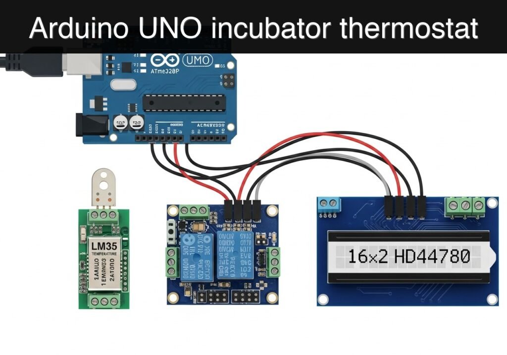
Architecture/flow: LM35 analog voltage → Arduino UNO ADC conversion → temperature calculation and threshold/hysteresis logic → relay toggles heater → 16×2 LCD and serial monitor display current temperature and heater status; no FPS or %GPU apply because this is a microcontroller-based control project.
Conceptual block diagram
High-level view: what enters the system, what each block processes, and what comes out.
Functional architecture
Conceptual signal and responsibility flow between device blocks.

Validation path
Conceptual summary of the tools used to check the published material.

Educational validation note
Before publication, this case passed the Prometeo automated validation gate with status PASS. The validator checked the code blocks, article structure, copy/paste-safe commands and consistency with the supported device catalog.
Published validation evidence
- Automatic result: PASS.
- Parsed structure: 3 sections, 3 tables and 3 code blocks detected before publication.
- Checked code: 1 Arduino/arduino-cli compile, 1 Bash/copy-paste checks.
- Supported catalog: the article text was checked against Prometeo’s validation-capable device profiles, and unsupported stacks block publication.
- Report findings: no blocking findings.
This validation confirms syntax and tool compatibility for the published material, but it does not replace physical testing on your exact hardware, wiring and runtime environment.
Educational safety note
This project is an educational prototype thermostat, not a certified temperature-control product.
Important limits and safety rules:
- Do not treat it as fail-safe. A software bug, wiring fault, stuck relay, bad sensor, or loose connection can cause overheating or loss of control.
- Prefer low-voltage heaters for beginner work. A low-voltage resistive heating element or lamp powered by an appropriate external supply is much safer for learning.
- Mains voltage warning: If your relay switches mains-powered heating, that introduces shock and fire risk. Beginners should not wire mains loads alone. Use qualified supervision and proper insulated enclosures, fusing, strain relief, and legal electrical practices.
- Do not power the heater from the Arduino. The UNO is only for control signals and low-power electronics.
- Never leave the prototype unattended while testing, especially inside an enclosed chamber.
- Keep the sensor away from direct heater contact. If the LM35 touches the heater, it may read heater surface temperature rather than chamber air temperature, causing poor control.
- Expect limited precision. The LM35, simple hysteresis control, relay switching, and enclosure design all limit stability.
- No safety certification: This build is not for industrial, food-production, commercial incubation, or any situation where failure could cause harm, fire, or property damage.
Prerequisites
Before starting, you should be comfortable with:
- Uploading a sketch to an Arduino UNO R3 (ATmega328P).
- Reading a breadboard layout in text form.
- Using a USB cable and a serial monitor.
- Basic DC wiring safety.
- Understanding that a relay is a switch, not a power source.
Recommended preparation:
- Install Arduino CLI on your computer.
- Have a known-good USB cable for the UNO.
- Decide whether your heater is:
- a low-voltage DC heating element controlled through the relay, or
- a mains-powered heater, which is not recommended for beginners without qualified supervision.
For an educational basic build, a small low-voltage heater is strongly preferred.
Materials
Use exactly this hardware set as the core device family and model:
- Arduino UNO R3 (ATmega328P) + LM35 analog temperature sensor + 1-channel relay module + 16×2 HD44780 LCD
Suggested full parts list:
| Item | Exact/Recommended Model | Qty | Notes |
|---|---|---|---|
| Microcontroller board | Arduino UNO R3 (ATmega328P) | 1 | Required |
| Temperature sensor | LM35 analog temperature sensor | 1 | Required |
| Relay board | 1-channel relay module, 5 V coil, Arduino-compatible | 1 | Required |
| Display | 16×2 HD44780 LCD, parallel interface | 1 | Required |
| Potentiometer | 10 kOhm trimmer | 1 | For LCD contrast |
| Resistor | 220 Ohm | 1 | LCD backlight current limiting if needed |
| Breadboard | Standard solderless breadboard | 1 | For wiring |
| Jumper wires | Male-to-male | 20+ | For all connections |
| USB cable | USB A to USB B | 1 | For UNO programming |
| Heater/load | Small low-voltage heater or lamp used as a heating source | 1 | Educational prototype load |
| External supply for heater | Matched to the heater | 1 | Do not power heater from the UNO |
| Optional enclosure | Small insulated box | 1 | For realistic incubator testing |
| Optional thermometer | Separate reference thermometer | 1 | Helpful for validation |
Setup/Connection
This project uses:
- LM35 for analog temperature measurement
- relay module for heater switching
- 16×2 HD44780 LCD in 4-bit mode for status display
Pin plan
Use this exact Arduino pin assignment in the sketch below:
- LM35 output ->
A0 - Relay input ->
D8 - LCD RS ->
D12 - LCD EN ->
D11 - LCD D4 ->
D5 - LCD D5 ->
D4 - LCD D6 ->
D3 - LCD D7 ->
D2
LM35 wiring
With the flat face of a typical TO-92 LM35 facing you and pins downward, the usual pinout is:
- Left pin ->
+5V - Middle pin ->
A0 - Right pin ->
GND
Always confirm your sensor’s datasheet or vendor labeling before powering it.
Relay module wiring
Most 1-channel relay modules have VCC, GND, and IN.
VCC->5VGND->GNDIN->D8
Relay load-side terminals are usually:
COMNO(Normally Open)NC(Normally Closed)
For a heater that should be off by default, use:
- power source line ->
COM - heater input ->
NO
The heater returns to its supply return path according to its own power circuit.
LCD wiring in 4-bit mode
Typical LCD pins:
VSS->GNDVDD->5VVO-> middle pin of 10 kOhm potentiometerRS->D12RW->GNDE->D11D0-> not connectedD1-> not connectedD2-> not connectedD3-> not connectedD4->D5D5->D4D6->D3D7->D2Aor LED+ ->5Vthrough220 Ohmresistor if neededKor LED- ->GND
Potentiometer for contrast:
- one outer pin ->
5V - other outer pin ->
GND - middle pin -> LCD
VOpin 3
Power and grounding rules
- The UNO, LM35, relay input side, and LCD must share a common ground.
- Do not power the heater from the Arduino 5 V pin.
- Use a separate power supply for the heater if required by the load.
- If you are controlling anything beyond low-voltage educational loads, get qualified supervision.
Control logic used in this build
This thermostat uses a hysteresis window:
- Turn heater on when temperature is below 36.5 C
- Turn heater off when temperature is above 37.5 C
That avoids relay chatter near the setpoint. You can change the thresholds in the code for your enclosure and heater.
Validated Code
lm35_incubator_thermostat.ino
Public preview of the validated file. The complete source is shown to members and in PDF/Print.
#include <LiquidCrystal.h>

// LCD pins: RS, E, D4, D5, D6, D7
LiquidCrystal lcd(12, 11, 5, 4, 3, 2);

const int LM35_PIN = A0;
const int RELAY_PIN = 8;

// Adjust these thresholds for your chamber.
// Hysteresis prevents rapid relay toggling.
const float TEMP_ON_C = 36.5;   // Heater turns ON below this
const float TEMP_OFF_C = 37.5;  // Heater turns OFF above this

// Set this to true if your relay module is active LOW.
// Many Arduino relay boards energize the relay when IN is LOW.
const bool RELAY_ACTIVE_LOW = true;

bool heaterOn = false;
unsigned long lastSampleMs = 0;
const unsigned long SAMPLE_INTERVAL_MS = 1000;

float readTemperatureC() {
  const int samples = 10;
  long sum = 0;

  for (int i = 0; i < samples; i++) {
    sum += analogRead(LM35_PIN);
    delay(5);
  }

  float averageAdc = sum / (float)samples;
  float voltage = averageAdc * (5.0 / 1023.0);

  // LM35 output is 10 mV per degree C
  float temperatureC = voltage * 100.0;
  return temperatureC;
}

void setRelay(bool on) {
  heaterOn = on;

  if (RELAY_ACTIVE_LOW) {
    digitalWrite(RELAY_PIN, on ? LOW : HIGH);
  } else {
    digitalWrite(RELAY_PIN, on ? HIGH : LOW);
  }
}

void updateControl(float temperatureC) {
  if (!heaterOn && temperatureC < TEMP_ON_C) {
    setRelay(true);
  } else if (heaterOn && temperatureC > TEMP_OFF_C) {
    setRelay(false);
  }
}
// ...#include <LiquidCrystal.h>
// LCD pins: RS, E, D4, D5, D6, D7
LiquidCrystal lcd(12, 11, 5, 4, 3, 2);
const int LM35_PIN = A0;
const int RELAY_PIN = 8;
// Adjust these thresholds for your chamber.
// Hysteresis prevents rapid relay toggling.
const float TEMP_ON_C = 36.5; // Heater turns ON below this
const float TEMP_OFF_C = 37.5; // Heater turns OFF above this
// Set this to true if your relay module is active LOW.
// Many Arduino relay boards energize the relay when IN is LOW.
const bool RELAY_ACTIVE_LOW = true;
bool heaterOn = false;
unsigned long lastSampleMs = 0;
const unsigned long SAMPLE_INTERVAL_MS = 1000;
float readTemperatureC() {
const int samples = 10;
long sum = 0;
for (int i = 0; i < samples; i++) {
sum += analogRead(LM35_PIN);
delay(5);
}
float averageAdc = sum / (float)samples;
float voltage = averageAdc * (5.0 / 1023.0);
// LM35 output is 10 mV per degree C
float temperatureC = voltage * 100.0;
return temperatureC;
}
void setRelay(bool on) {
heaterOn = on;
if (RELAY_ACTIVE_LOW) {
digitalWrite(RELAY_PIN, on ? LOW : HIGH);
} else {
digitalWrite(RELAY_PIN, on ? HIGH : LOW);
}
}
void updateControl(float temperatureC) {
if (!heaterOn && temperatureC < TEMP_ON_C) {
setRelay(true);
} else if (heaterOn && temperatureC > TEMP_OFF_C) {
setRelay(false);
}
}
void updateDisplay(float temperatureC) {
  lcd.setCursor(0, 0);
  lcd.print("Temp: ");
  lcd.print(temperatureC, 1);
  lcd.print((char)223); // degree symbol
  lcd.print("C   ");

  lcd.setCursor(0, 1);
  lcd.print("Set ");
  lcd.print(TEMP_ON_C, 1);
  lcd.print("-");
  lcd.print(TEMP_OFF_C, 1);
  lcd.print(" ");

  lcd.setCursor(12, 1);
  if (heaterOn) {
    lcd.print("ON ");
  } else {
    lcd.print("OFF");
  }
}

void printSerial(float temperatureC) {
  Serial.print("Temperature_C=");
  Serial.print(temperatureC, 2);
  Serial.print(", Heater=");
  Serial.println(heaterOn ? "ON" : "OFF");
}
void setup() {
pinMode(RELAY_PIN, OUTPUT);
// Start with heater off
setRelay(false);
lcd.begin(16, 2);
lcd.clear();
lcd.setCursor(0, 0);
lcd.print("Incubator Ctrl");
lcd.setCursor(0, 1);
lcd.print("Starting...");
Serial.begin(9600);
delay(1500);
lcd.clear();
}
void loop() {
unsigned long now = millis();
if (now - lastSampleMs >= SAMPLE_INTERVAL_MS) {
lastSampleMs = now;
float temperatureC = readTemperatureC();
updateControl(temperatureC);
updateDisplay(temperatureC);
printSerial(temperatureC);
}
}
Optional serial log pattern for comparison
This is not a second program. It is an example of what a healthy run may look like in the serial monitor while the sensor warms up:
Temperature_C=29.86, Heater=ON
Temperature_C=30.10, Heater=ON
Temperature_C=31.02, Heater=ON
Temperature_C=34.88, Heater=ON
Temperature_C=36.42, Heater=ON
Temperature_C=37.61, Heater=OFF
Temperature_C=37.43, Heater=OFF
Temperature_C=36.28, Heater=ON
Interpretation:
- The heater stays ON until the reading rises above
TEMP_OFF_C. - It stays OFF until the reading falls below
TEMP_ON_C. - This confirms the hysteresis behavior.
Build/Flash/Run commands
Use Arduino CLI, not PlatformIO.
Command table
| Task | Command |
|---|---|
| Update board index | arduino-cli core update-index |
| Install AVR core | arduino-cli core install arduino:avr |
| Compile sketch | arduino-cli compile --fqbn arduino:avr:uno ./lm35_incubator_thermostat |
| Upload sketch | arduino-cli upload --fqbn arduino:avr:uno --port <PORT> ./lm35_incubator_thermostat |
| Open serial monitor | arduino-cli monitor --port <PORT> --config baudrate=9600 |
Short workflow
- Create a project folder named
lm35_incubator_thermostat. - Save the sketch as:
lm35_incubator_thermostat/lm35_incubator_thermostat.ino- Run the commands in order:
arduino-cli core update-index
arduino-cli core install arduino:avr
arduino-cli compile --fqbn arduino:avr:uno ./lm35_incubator_thermostat
arduino-cli upload --fqbn arduino:avr:uno --port <PORT> ./lm35_incubator_thermostat
arduino-cli monitor --port <PORT> --config baudrate=9600
- Replace
<PORT>with your actual serial port: - Linux example:
/dev/ttyACM0 - Windows example:
COM4 - macOS example:
/dev/cu.usbmodem14101
Step-by-step Validation
Use these checkpoints in order. They are grouped to keep validation practical and repeatable.
1. Power-up and LCD bring-up
What to do:
– Power the UNO from USB.
– Adjust the LCD contrast potentiometer slowly.
Expected observation:
– The LCD first shows:
– Incubator Ctrl
– Starting...
– Then it updates to temperature and heater status.
Pass condition:
– The LCD is readable and continues updating once per second.
– If the backlight is on but no text appears, the contrast setting or wiring needs correction.
2. Sensor sanity check
What to do:
– Leave the LM35 at room temperature for 30-60 seconds.
– Open the serial monitor at 9600 baud.
– Compare the displayed value to room conditions or a separate thermometer if available.
Expected observation:
– The reading should be plausible for the room, typically around 20-35 C depending on your environment.
– Serial output should print one line every second.
Pass condition:
– The temperature does not stay stuck at 0.0 C, 50+ C in a normal room, or jump randomly by very large amounts.
– LCD and serial values should match closely.
3. Controlled warming test
What to do:
– Warm the LM35 gently using your fingers, or move it near warm air without overheating it.
– Watch the LCD and serial output.
Expected observation:
– The measured temperature rises gradually.
– Once it crosses 37.5 C, the relay state changes to OFF if it was previously ON.
Pass condition:
– The temperature responds to warming in a smooth, believable way.
– The relay changes state when the threshold is crossed.
4. Controlled cooling test
What to do:
– Let the LM35 cool naturally back toward room temperature.
– If needed, remove the heat source and wait several minutes.
Expected observation:
– The temperature falls gradually.
– When it goes below 36.5 C, the relay changes to ON.
Pass condition:
– The relay does not rapidly chatter on and off near one exact temperature.
– It follows the hysteresis rule: off above the upper threshold, on below the lower threshold.
5. Chamber behavior test with real heater load
What to do:
– Place the LM35 in the same air space as the heater inside a small enclosure.
– Run the system for 10-20 minutes using a low-voltage educational heater setup.
Expected observation:
– Temperature increases when heating starts.
– Relay eventually turns the heater off near the upper threshold.
– Temperature then drifts downward until the heater turns back on.
Pass condition:
– The enclosure cycles between the two thresholds.
– The system behaves as a thermostat, not as a one-time switch.
Troubleshooting
| Symptom | Likely cause | Fix |
|---|---|---|
| LCD backlight on but no text | Contrast misadjusted, RW not tied to GND, wrong pin wiring | Adjust potentiometer, verify LCD pins 4/5/6/11/12/13/14, ensure RW is GND |
| LCD shows text but temperature is 0.0 C | LM35 output not reaching A0, wrong LM35 orientation | Recheck sensor pinout and A0 connection |
| Temperature reading is far too high or unstable | Floating ground, noisy wiring, wrong sensor pinout | Confirm common ground, shorten sensor leads, recheck LM35 orientation |
| Relay never changes state | Wrong relay input polarity | Toggle RELAY_ACTIVE_LOW between true and false |
| Relay clicks but heater does not turn on | Wrong COM/NO wiring on load side, heater power supply issue | Recheck relay terminal wiring and external heater power path |
| Relay chatters rapidly | Thresholds too close, chamber too small, sensor too near heater | Increase hysteresis gap, move sensor away from direct radiant heat |
| Serial upload fails | Wrong port or board selected | Use correct <PORT> and arduino:avr:uno FQBN |
| Temperature overshoots too much | Heater too powerful, poor airflow, sensor placement issue | Reduce heater power, add gentle airflow, move sensor to representative air location |
Improvements
Control and measurement improvements
- Adjustable setpoint: Add buttons or a rotary encoder so the target range can be changed without editing code.
- Calibration offset: Add a software offset if your LM35 consistently differs from a reference thermometer by a small amount.
- Longer averaging: Increase the sample count or use a moving average to reduce display noise.
Enclosure and thermal design improvements
- Better sensor placement: Put the LM35 in the air stream or center of the chamber, not touching the heater or chamber wall.
- Air circulation: A small low-voltage fan can improve temperature uniformity inside the incubator.
- Insulation: Better enclosure insulation reduces relay cycling and makes the chamber more stable.
Usability and reliability improvements
- Alarm indication: Add a buzzer or LED if temperature goes far above or below the intended range.
- Minimum relay off-time: Add timing rules to reduce wear if your heater is very responsive.
- Data logging: Send serial data to a PC for recording temperature trends over time.
Final Checklist
Use this checklist before calling the project complete:
- [ ] I used Arduino UNO R3 (ATmega328P) exactly.
- [ ] I used LM35 analog temperature sensor + 1-channel relay module + 16×2 HD44780 LCD exactly.
- [ ] The LCD wiring matches the sketch pin mapping.
- [ ] The LM35 output goes to
A0, with correct power and ground orientation. - [ ] The relay input goes to
D8. - [ ] The UNO, relay input side, LM35, and LCD share a common ground.
- [ ] The heater uses its own proper power path and is not powered from the UNO.
- [ ] The sketch compiles with:
- [ ]
arduino-cli core update-index - [ ]
arduino-cli core install arduino:avr - [ ]
arduino-cli compile --fqbn arduino:avr:uno ./lm35_incubator_thermostat - [ ] The sketch uploads with:
- [ ]
arduino-cli upload --fqbn arduino:avr:uno --port <PORT> ./lm35_incubator_thermostat - [ ] The LCD shows temperature and heater state.
- [ ] The serial monitor prints one reading per second at 9600 baud.
- [ ] Warming the LM35 raises the displayed temperature.
- [ ] The relay turns off above the upper threshold and on below the lower threshold.
- [ ] The chamber cycles within the hysteresis band during a supervised test.
- [ ] I understand this is an educational prototype and not a fail-safe incubator controller.
Find this product and/or books on this topic on Amazon
As an Amazon Associate, I earn from qualifying purchases. If you buy through this link, you help keep this project running.
Quick Quiz

Telecommunications Electronics Engineer and Computer Engineer (official degrees in Spain).

