
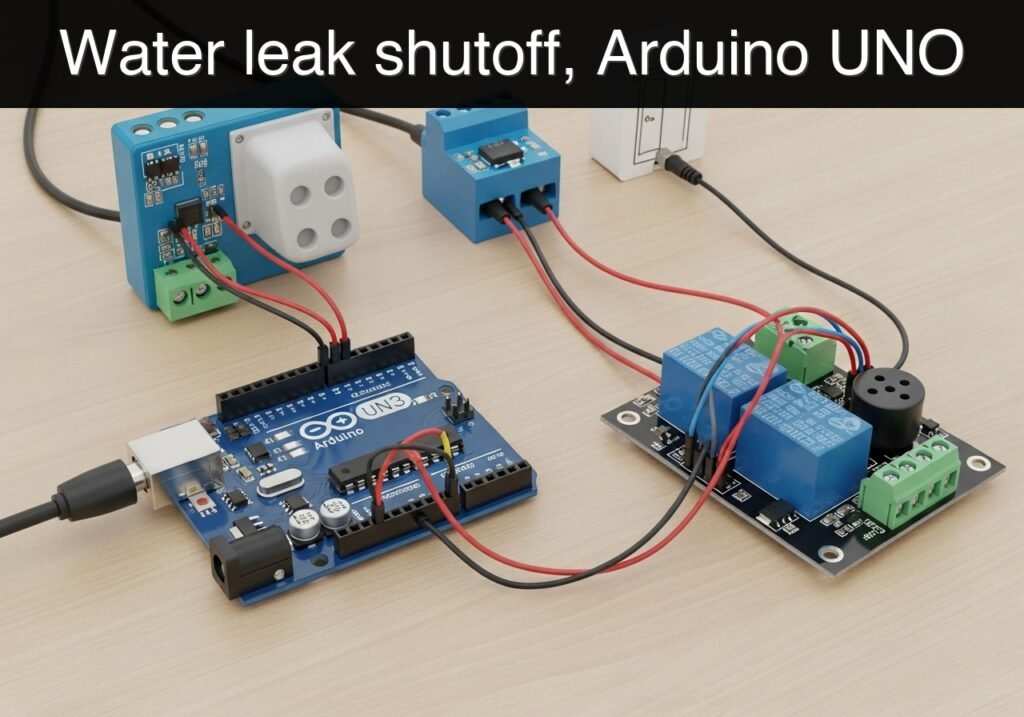
Objective and use case
What you’ll build: A basic water leak shutoff relay controller using an Arduino UNO R3, water leak sensor, 1-channel relay module, and piezo buzzer. When water is detected, the Arduino switches the relay within roughly 10–50 ms to shut off a connected low-voltage control circuit and immediately sounds a local alarm.
Why it matters / Use cases
- Under-sink protection: Detect drips under a kitchen or bathroom sink and cut a 5–12 V valve or pump-enable line before standing water spreads through the cabinet.
- Washing machine area monitoring: Place the sensor in a tray near the washer so a floor leak triggers an audible buzzer and opens or closes the relay to disable a water solenoid control path.
- Basement or utility room response: Catch early leaks near a water heater, filter, or sump plumbing and send a fast shutoff signal while providing immediate on-site alerting.
- Educational automation prototype: Learn digital sensing, relay-safe switching, and event-driven control on an 8-bit microcontroller with near-zero idle latency and typically <1% UNO CPU load for this simple loop.
Expected outcome
- An Arduino sketch that continuously reads the leak sensor and changes relay state as soon as water is detected.
- A buzzer alarm that activates at the same time as the shutoff event for clear local notification.
- A low-cost prototype suitable for bench testing with 5 V electronics and low-voltage valve, pump, or controller interlock circuits.
- A repeatable response flow with practical timing: sensor wetting to relay action in tens of milliseconds, with no GPU usage and no FPS dependency.
Audience: Arduino beginners, makers, and building-automation learners; Level: Beginner
Architecture/flow: Water leak sensor detects moisture → Arduino UNO reads digital/thresholded input in the main loop → relay energizes or de-energizes based on fail-safe wiring choice → buzzer sounds until the leak clears or the system is reset.
Educational validation note
Before publication, this case passed the Prometeo automated validation gate with status PASS. The validator checked the code blocks, article structure, copy/paste-safe commands and consistency with the supported device catalog.
Published validation evidence
- Automatic result: PASS.
- Parsed structure: 3 sections, 4 tables and 3 code blocks detected before publication.
- Checked code: 1 Arduino/arduino-cli compile, 1 C/C++ static checks, 1 Bash/copy-paste checks.
- Supported catalog: the article text was checked against Prometeo’s validation-capable device profiles, and unsupported stacks block publication.
- Report findings: no blocking findings.
This validation confirms syntax and tool compatibility for the published material, but it does not replace physical testing on your exact hardware, wiring and runtime environment.
Educational safety note
This project is an educational prototype, not a certified building protection system. Treat it as a learning controller and bench-scale leak response aid.
Important limits and precautions:
- Do not connect mains voltage directly unless you are qualified to design and test mains-safe relay systems. For beginner use, keep the relay on a low-voltage circuit only.
- The relay module in this tutorial should be used to switch:
- low-voltage valve control wiring
- a low-voltage enable input
- a demonstration load
not household AC plumbing equipment unless properly engineered. - Water and electronics must be kept physically separated:
- only the leak sensor should be exposed to water
- keep the Arduino, relay board, USB cable, and buzzer dry
- A corroded or contaminated leak sensor may trigger false alarms or fail to detect properly. Periodic inspection is required.
- USB power from a computer is acceptable for lab testing, but a field installation would require a more deliberate power design and enclosure strategy.
- This design has no certified fail-safe guarantee, no battery backup, and no tamper detection.
- If used near pumps, valves, or higher-current actuators, confirm that the relay contacts are rated for the actual load and that inductive loads are suppressed appropriately.
- Never rely on this prototype alone to prevent property damage in high-risk environments.
Conceptual block diagram
High-level view: what enters the system, what each block processes, and what comes out.
Functional architecture
Conceptual signal and responsibility flow between device blocks.

Validation path
Conceptual summary of the tools used to check the published material.

Prerequisites
Before starting, you should have:
- Basic familiarity with:
- plugging jumper wires into Arduino pins
- selecting a board and serial port
- uploading an Arduino sketch
- A computer with:
- Arduino CLI installed
- USB cable for the Arduino UNO R3
- A dry workspace and a small container or paper towel for controlled water testing
- A low-voltage load or control loop to connect to the relay contacts for demonstration
- Examples:
- a 12 V DC valve control line
- a small DC pump enable line
- an LED test lamp powered separately
- For a beginner lab, an LED or buzzer on the relay contact side is safer than connecting any real plumbing hardware at first
Materials
Use exactly this device family/model combination:
Arduino UNO R3 (ATmega328P) + water leak sensor + 1-channel relay module + piezo buzzer
Recommended material list:
| Item | Exact/Recommended Type | Purpose |
|---|---|---|
| Main controller | Arduino UNO R3 (ATmega328P) | Runs the leak detection and relay logic |
| Sensor | Water leak sensor module with analog and/or digital output | Detects presence of water on exposed traces |
| Relay output | 1-channel relay module, 5 V coil, Arduino-compatible input | Switches the external shutoff control circuit |
| Alarm | Piezo buzzer, 5 V compatible | Local audible warning |
| Wiring | Male-male jumper wires | Connections between modules |
| USB cable | USB A to USB B | Power and programming |
| Test load | Low-voltage lamp, LED module, or a disabled valve control loop | Safe demonstration of relay action |
| Optional | Small towel, cup, spray bottle | Controlled water testing |
| Optional | Breadboard | Cleaner buzzer wiring if needed |
Notes about the exact model combination
- The Arduino UNO R3 (ATmega328P) is the only controller used here.
- The water leak sensor may expose:
- AO: analog output
- DO: digital threshold output from an onboard comparator
- In this tutorial, we will use the analog output for more stable and understandable filtering.
- The relay module is assumed to have:
- VCC
- GND
- IN
- screw terminals such as COM, NO, and NC
- The piezo buzzer is treated as a simple two-wire buzzer.
Setup/Connection
This project has two parts:
- Logic side: Arduino, sensor, relay input, buzzer
- Relay contact side: the external low-voltage circuit that you want to interrupt or enable
Pin assignment used in this tutorial
| Arduino UNO pin | Connected device pin | Function |
|---|---|---|
| 5V | Sensor VCC | Power for leak sensor |
| GND | Sensor GND | Common ground |
| A0 | Sensor AO | Analog leak reading |
| 5V | Relay VCC | Power for relay module |
| GND | Relay GND | Common ground |
| D8 | Relay IN | Relay control signal |
| D9 | Buzzer positive | Buzzer drive pin |
| GND | Buzzer negative | Buzzer return |
Sensor connection steps
- Connect the water leak sensor VCC to 5V on the Arduino.
- Connect the sensor GND to GND on the Arduino.
- Connect the sensor AO to A0 on the Arduino.
- If your sensor also has DO, leave it unused in this tutorial.
Relay module connection steps
- Connect relay VCC to Arduino 5V.
- Connect relay GND to Arduino GND.
- Connect relay IN to Arduino D8.
Piezo buzzer connection steps
- Connect the buzzer positive lead to D9.
- Connect the buzzer negative lead to GND.
Relay contact side: how to use the shutoff function
The relay module provides isolated switch contacts, usually:
- COM: common
- NO: normally open
- NC: normally closed
For a water-leak-shutoff-relay objective, the most practical beginner setup is:
- Put the relay in series with the low-voltage control line of the device you want to stop.
- Choose COM + NC if you want the circuit connected during normal dry operation and disconnected when leak alarm activates.
- Choose COM + NO if you want the circuit disconnected during normal dry operation and connected only during alarm. This is less common for shutoff.
Recommended beginner contact arrangement
For a simple shutoff controller:
- External low-voltage source/control wire -> COM
- Relay NC -> load/control input
Result:
- Dry state: COM and NC are connected, so the load/control circuit is allowed.
- Leak state: relay switches away from NC, opening the control path and creating a shutoff action.
Important setup note about relay logic
Some relay modules are active LOW:
- writing
LOWto the input turns relay ON - writing
HIGHturns relay OFF
Others are active HIGH.
The sketch below supports this using one configuration constant so you do not have to rewrite the logic.
Validated Code
Complete Arduino sketch: water_leak_shutoff_relay.ino
Public preview of the validated file. The complete source is shown to members and in PDF/Print.
/*
  water_leak_shutoff_relay.ino

  Device model:
  Arduino UNO R3 (ATmega328P) + water leak sensor + 1-channel relay module + piezo buzzer

  Goal:
  Detect water using analog input, confirm the leak with simple timing/filter logic,
  trigger an audible alarm, and switch a relay for shutoff control.

  Serial output:
  9600 baud
*/

const int SENSOR_PIN = A0;
const int RELAY_PIN = 8;
const int BUZZER_PIN = 9;

// Relay module behavior:
// true  = relay input is active LOW
// false = relay input is active HIGH
const bool RELAY_ACTIVE_LOW = true;

// Sensor thresholds:
// Lower analog readings often mean "more water" on many common modules,
// but some modules behave differently. Validate with Serial Monitor first.
const int LEAK_THRESHOLD_WET = 500;   // Reading at or below this means "wet"
const int LEAK_THRESHOLD_DRY = 560;   // Reading at or above this means "dry again"

// Timing filters to avoid false triggers from noise or tiny splashes
const unsigned long WET_CONFIRM_MS = 400;
const unsigned long DRY_CONFIRM_MS = 1500;
const unsigned long STATUS_PRINT_MS = 500;

// Buzzer pattern timing
const unsigned long BUZZER_ON_MS = 180;
const unsigned long BUZZER_OFF_MS = 220;

bool leakAlarm = false;

unsigned long wetStartMs = 0;
unsigned long dryStartMs = 0;
unsigned long lastStatusPrintMs = 0;
unsigned long buzzerToggleMs = 0;
bool buzzerState = false;

void setRelayAlarmState(bool alarmActive) {
  // For shutoff wiring using COM + NC:
  // alarmActive should cause the relay to switch away from NC.
  bool relayEnergized = alarmActive;

  if (RELAY_ACTIVE_LOW) {
    digitalWrite(RELAY_PIN, relayEnergized ? LOW : HIGH);
  } else {
    digitalWrite(RELAY_PIN, relayEnergized ? HIGH : LOW);
  }
}

void setBuzzer(bool on) {
  if (on) {
    tone(BUZZER_PIN, 2400);  // 2.4 kHz tone
  } else {
    noTone(BUZZER_PIN);
  }
}

void printState(const char* stateName, int sensorValue) {
  Serial.print("State: ");
  Serial.print(stateName);
  Serial.print(" | sensor=");
  Serial.print(sensorValue);
  Serial.print(" | relay_alarm=");
  Serial.println(leakAlarm ? "ON" : "OFF");
}
// .../*
water_leak_shutoff_relay.ino
Device model:
Arduino UNO R3 (ATmega328P) + water leak sensor + 1-channel relay module + piezo buzzer
Goal:
Detect water using analog input, confirm the leak with simple timing/filter logic,
trigger an audible alarm, and switch a relay for shutoff control.
Serial output:
9600 baud
*/
const int SENSOR_PIN = A0;
const int RELAY_PIN = 8;
const int BUZZER_PIN = 9;
// Relay module behavior:
// true = relay input is active LOW
// false = relay input is active HIGH
const bool RELAY_ACTIVE_LOW = true;
// Sensor thresholds:
// Lower analog readings often mean "more water" on many common modules,
// but some modules behave differently. Validate with Serial Monitor first.
const int LEAK_THRESHOLD_WET = 500; // Reading at or below this means "wet"
const int LEAK_THRESHOLD_DRY = 560; // Reading at or above this means "dry again"
// Timing filters to avoid false triggers from noise or tiny splashes
const unsigned long WET_CONFIRM_MS = 400;
const unsigned long DRY_CONFIRM_MS = 1500;
const unsigned long STATUS_PRINT_MS = 500;
// Buzzer pattern timing
const unsigned long BUZZER_ON_MS = 180;
const unsigned long BUZZER_OFF_MS = 220;
bool leakAlarm = false;
unsigned long wetStartMs = 0;
unsigned long dryStartMs = 0;
unsigned long lastStatusPrintMs = 0;
unsigned long buzzerToggleMs = 0;
bool buzzerState = false;
void setRelayAlarmState(bool alarmActive) {
// For shutoff wiring using COM + NC:
// alarmActive should cause the relay to switch away from NC.
bool relayEnergized = alarmActive;
if (RELAY_ACTIVE_LOW) {
digitalWrite(RELAY_PIN, relayEnergized ? LOW : HIGH);
} else {
digitalWrite(RELAY_PIN, relayEnergized ? HIGH : LOW);
}
}
void setBuzzer(bool on) {
if (on) {
tone(BUZZER_PIN, 2400); // 2.4 kHz tone
} else {
noTone(BUZZER_PIN);
}
}
void printState(const char* stateName, int sensorValue) {
Serial.print("State: ");
Serial.print(stateName);
Serial.print(" | sensor=");
Serial.print(sensorValue);
Serial.print(" | relay_alarm=");
Serial.println(leakAlarm ? "ON" : "OFF");
}
void setup() {
  pinMode(RELAY_PIN, OUTPUT);
  pinMode(BUZZER_PIN, OUTPUT);

  // Default safe startup for this tutorial:
  // no alarm until a confirmed leak is detected.
  leakAlarm = false;
  setRelayAlarmState(leakAlarm);
  setBuzzer(false);

  Serial.begin(9600);
  delay(300);
  Serial.println("Water leak shutoff relay controller starting...");
  Serial.println("Using analog leak sensing on A0");
  Serial.println("Check dry and wet readings before final installation.");

  // Initialize timing references
  wetStartMs = 0;
  dryStartMs = 0;
  lastStatusPrintMs = 0;
  buzzerToggleMs = 0;
  buzzerState = false;
}

void loop() {
  unsigned long now = millis();
  int sensorValue = analogRead(SENSOR_PIN);
bool wetCandidate = (sensorValue <= LEAK_THRESHOLD_WET);
bool dryCandidate = (sensorValue >= LEAK_THRESHOLD_DRY);
// Leak detection state machine with hysteresis and timing confirmation
if (!leakAlarm) {
if (wetCandidate) {
if (wetStartMs == 0) {
wetStartMs = now;
}
if (now - wetStartMs >= WET_CONFIRM_MS) {
leakAlarm = true;
dryStartMs = 0;
setRelayAlarmState(leakAlarm);
Serial.println("LEAK DETECTED: relay shutoff activated");
printState("LEAK", sensorValue);
}
} else {
wetStartMs = 0;
}
} else {
if (dryCandidate) {
if (dryStartMs == 0) {
dryStartMs = now;
}
if (now - dryStartMs >= DRY_CONFIRM_MS) {
leakAlarm = false;
wetStartMs = 0;
setRelayAlarmState(leakAlarm);
setBuzzer(false);
buzzerState = false;
Serial.println("RESET TO DRY: relay returned to normal");
printState("DRY", sensorValue);
}
} else {
dryStartMs = 0;
}
}
// Buzzer pattern during active alarm
if (leakAlarm) {
if (now - buzzerToggleMs >= (buzzerState ? BUZZER_ON_MS : BUZZER_OFF_MS)) {
buzzerState = !buzzerState;
setBuzzer(buzzerState);
buzzerToggleMs = now;
}
} else {
if (buzzerState) {
buzzerState = false;
setBuzzer(false);
}
}
// Periodic status prints
if (now - lastStatusPrintMs >= STATUS_PRINT_MS) {
printState(leakAlarm ? "LEAK" : "DRY", sensorValue);
lastStatusPrintMs = now;
}
delay(20);
}
How to calibrate the threshold if your sensor behaves differently
Many low-cost leak sensor boards change analog value when wet, but the direction and range can vary.
Before final use:
- Upload the sketch as-is.
- Open the serial monitor.
- Note the analog readings:
- fully dry
- slightly damp
- definitely wet
- Adjust:
LEAK_THRESHOLD_WETLEAK_THRESHOLD_DRY
Use a gap between them to create hysteresis, which helps prevent rapid switching.
Example of a threshold edit if your sensor is dry near 850 and wet near 300:
const int LEAK_THRESHOLD_WET = 450;
const int LEAK_THRESHOLD_DRY = 700;
Build/Flash/Run commands
Command table
| Task | Command |
|---|---|
| Update board index | arduino-cli core update-index |
| Install AVR core | arduino-cli core install arduino:avr |
| Compile sketch | arduino-cli compile --fqbn arduino:avr:uno ./water_leak_shutoff_relay |
| Upload sketch | arduino-cli upload --fqbn arduino:avr:uno --port <PORT> ./water_leak_shutoff_relay |
| Optional board list | arduino-cli board list |
| Optional serial monitor | arduino-cli monitor --port <PORT> --config 9600 |
Workflow
- Create a project folder named
water_leak_shutoff_relay. - Save the sketch as:
water_leak_shutoff_relay/water_leak_shutoff_relay.ino- Run the required commands:
arduino-cli core update-index
arduino-cli core install arduino:avr
arduino-cli compile --fqbn arduino:avr:uno ./water_leak_shutoff_relay
arduino-cli upload --fqbn arduino:avr:uno --port <PORT> ./water_leak_shutoff_relay
- Find your serial port if needed:
- Linux example:
/dev/ttyACM0 - Windows example:
COM4 - macOS example:
/dev/cu.usbmodem14101 - Open a serial monitor at 9600 baud to observe readings and state changes.
Step-by-step Validation
Use these checkpoints in order. Each checkpoint includes the expected observation and pass condition.
1. Power-up and idle-state check
- Action:
- Power the Arduino by USB.
- Keep the sensor dry and not touching metal or water.
- Expected observation:
- Serial Monitor prints startup text.
- Repeating status lines show
State: DRY. - The buzzer stays silent.
- The relay remains in its normal non-alarm state.
- Pass condition:
- No alarm occurs while the sensor is dry for at least 30 seconds.
2. Dry reading baseline capture
- Action:
- Watch the printed
sensor=values for 10 to 20 seconds. - Write down the typical dry range.
- Expected observation:
- Sensor values stay fairly consistent with small fluctuations.
- Pass condition:
- Dry readings remain clearly on one side of
LEAK_THRESHOLD_DRY. - If not, you must recalibrate thresholds before continuing.
3. Controlled wet trigger test
- Action:
- Put a few drops of water on the sensing area, or touch it with a damp paper towel.
- Expected observation:
- Sensor value crosses the wet threshold.
- After about
WET_CONFIRM_MS, the serial monitor printsLEAK DETECTED. - The buzzer starts pulsing.
- The relay changes state.
- Pass condition:
- Alarm is not instantaneous from noise, but does trigger reliably when the sensor is truly wet.
4. Shutoff relay behavior verification
- Action:
- Connect a safe low-voltage test circuit through the relay contacts, preferably using COM + NC for normal-through, alarm-open operation.
- Repeat the wet trigger test.
- Expected observation:
- In dry state, the external low-voltage circuit is complete.
- In leak state, the circuit is interrupted.
- Pass condition:
- The relay contacts perform the intended shutoff function consistently for at least 5 test cycles.
5. Dry recovery and anti-chatter check
- Action:
- Remove water and dry the sensor thoroughly.
- Observe whether the system resets only after stable dryness.
- Expected observation:
- The buzzer continues until the sensor returns above
LEAK_THRESHOLD_DRYfor aboutDRY_CONFIRM_MS. - Then serial prints
RESET TO DRY. - Relay returns to normal state.
- Pass condition:
- No rapid relay clicking or repeated false toggling during the drying transition.
Troubleshooting
| Symptom | Likely cause | Fix |
|---|---|---|
| Relay seems backward: shutoff happens in dry state | Relay input polarity or contact choice is opposite of expected | Change RELAY_ACTIVE_LOW, or move the load from NO to NC as appropriate |
| Sensor always reads wet | Threshold too high, sensor contaminated, or water already bridging traces | Clean and dry the sensor, inspect readings, lower wet threshold |
| Sensor never triggers on water | Threshold too low, wrong pin used, or sensor output type misunderstood | Confirm AO is connected to A0, watch serial values while wet, adjust thresholds |
| Buzzer does not sound | Wrong buzzer polarity, passive/active type mismatch, or wiring error | Recheck D9 and GND, test buzzer separately, ensure tone()-compatible buzzer |
| Relay chatters near threshold | Noisy sensor values or insufficient hysteresis | Increase gap between wet and dry thresholds; increase confirm times |
| Upload fails | Wrong port or missing AVR core | Run arduino-cli board list, verify <PORT>, rerun core install |
| Serial output is unreadable | Wrong baud rate | Set monitor to 9600 baud |
| Relay module resets Arduino or behaves oddly | Power draw/noise issue or poor wiring | Keep wiring short, ensure solid 5 V/GND connections, test modules individually |
Improvements
Reliability and installation quality
- Add a sensor tray or mount the leak sensor at the lowest point where water would collect first.
- Use a second leak sensor in parallel logic for two-zone coverage, such as one under a sink and one behind an appliance.
- Add a latched alarm mode so that once a leak is detected, a manual reset is required even after drying.
- Put the Arduino and relay in a small enclosure, with the sensor on a cable extending to the monitored area.
Better control behavior
- Add a manual test button to simulate a leak without using water.
- Add a mute button that silences the buzzer but keeps the relay in shutoff state.
- Log event counts or timestamps over serial so a student can document repeated test cycles.
Safer real-world integration
- Use the relay to control only a low-voltage valve or control interface, not unknown high-power wiring.
- Replace the piezo buzzer with a panel-mounted buzzer for clearer audible alerting.
- If a real shutoff valve is later added, choose a valve that has a clear fail-safe behavior and compatible control voltage.
Final Checklist
- [ ] I used Arduino UNO R3 (ATmega328P) + water leak sensor + 1-channel relay module + piezo buzzer.
- [ ] The sensor is wired to A0, relay input to D8, buzzer to D9.
- [ ] I connected all grounds together.
- [ ] I saved the sketch as
water_leak_shutoff_relay.ino. - [ ] I ran:
- [ ]
arduino-cli core update-index - [ ]
arduino-cli core install arduino:avr - [ ]
arduino-cli compile --fqbn arduino:avr:uno ./water_leak_shutoff_relay - [ ]
arduino-cli upload --fqbn arduino:avr:uno --port <PORT> ./water_leak_shutoff_relay - [ ] I verified dry-state serial readings.
- [ ] I calibrated
LEAK_THRESHOLD_WETandLEAK_THRESHOLD_DRYif needed. - [ ] I tested leak detection with a controlled small amount of water.
- [ ] I confirmed the buzzer pattern activates during a leak.
- [ ] I confirmed the relay interrupts the intended low-voltage control path during a leak.
- [ ] I dried the sensor and verified clean recovery to normal state.
- [ ] I understand this is an educational prototype, not a certified safety system.
Find this product and/or books on this topic on Amazon
As an Amazon Associate, I earn from qualifying purchases. If you buy through this link, you help keep this project running.
Quick Quiz

Telecommunications Electronics Engineer and Computer Engineer (official degrees in Spain).

