
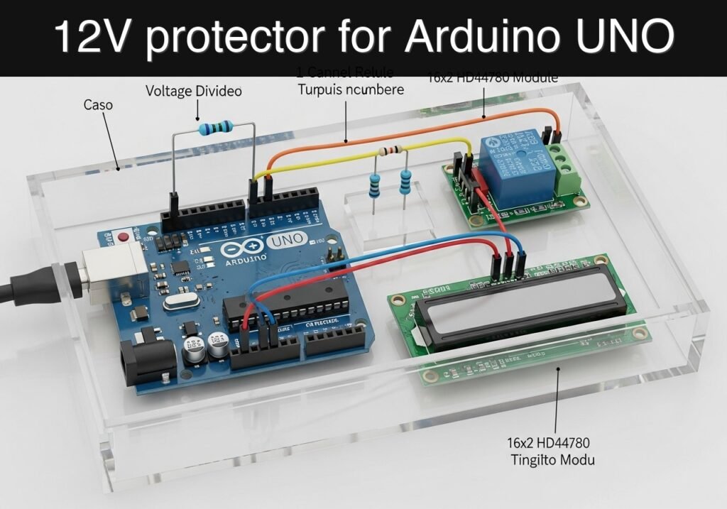
Objective and use case
What you’ll build: A 12 V low-battery load disconnect controller using an Arduino UNO R3, voltage divider, 1-channel relay module, and 16×2 HD44780 LCD. It continuously samples battery voltage, displays the live reading on the LCD, and cuts power to the load when the battery drops below a safe threshold such as 11.8 V, then reconnects only after recovery with hysteresis.
Why it matters / Use cases
- Protect a small 12 V lead-acid battery in a solar shed, lighting box, or portable power setup by disconnecting loads like LED strips, a 5–20 W fan, or small DC accessories before damaging deep discharge occurs.
- Prevent “mystery dead battery” problems in hobby projects that run overnight by placing the controller between the battery and load, preserving usable charge for the next day.
- Provide an educational battery monitor for labs and workshops where students can watch live voltage updates on the LCD, test cutoff points, and observe how hysteresis prevents rapid relay chatter near the threshold.
Expected outcome
- Voltage measurement refreshed about 2–5 times per second on the LCD with practical monitoring latency under 500 ms.
- Automatic relay cutoff when battery voltage falls below a defined limit, for example 11.8 V, with reconnect above a higher threshold such as 12.4 V.
- Stable switching behavior with minimal Arduino UNO load, typically well under 10% CPU usage and no meaningful GPU usage.
- A reusable protection module that can be retuned for different 12 V systems by adjusting divider calibration and voltage thresholds.
Audience: Arduino beginners, students, and hobbyists building battery-powered systems; Level: beginner to intermediate
Architecture/flow: 12 V battery → voltage divider → Arduino analog input for scaled sensing; Arduino → 16×2 LCD for live voltage/status display; Arduino digital output → 1-channel relay module → load disconnect/reconnect based on threshold and hysteresis logic.
Educational validation note
Before publication, this case passed the Prometeo automated validation gate with status PASS. The validator checked the code blocks, article structure, copy/paste-safe commands and consistency with the supported device catalog.
Published validation evidence
- Automatic result: PASS.
- Parsed structure: 3 sections, 4 tables and 3 code blocks detected before publication.
- Checked code: 1 Arduino/arduino-cli compile, 1 Bash/copy-paste checks.
- Supported catalog: the article text was checked against Prometeo’s validation-capable device profiles, and unsupported stacks block publication.
- Report findings: no blocking findings.
This validation confirms syntax and tool compatibility for the published material, but it does not replace physical testing on your exact hardware, wiring and runtime environment.
Educational safety note
This project is a low-voltage educational prototype, not a certified battery protection product. Its limits must be understood clearly.
- Battery safety
- Even at 12 V, batteries can deliver very high current.
- A wiring mistake can overheat wires, damage the battery, or cause sparks.
Use an inline fuse on the battery positive lead when moving beyond breadboard demonstration.
Relay contact safety
- The relay module controls the load path, but its contact rating must match the actual load.
- Do not switch loads that exceed the module’s current or voltage specification.
Do not assume the relay module is suitable for inductive, motor, or surge-heavy loads without proper protection.
No mains voltage
- This tutorial should be used only for low-voltage DC educational work.
Do not use the relay module to switch household mains unless you have formal training, proper isolation practices, and compliant hardware. That is outside the scope of this basic tutorial.
Breadboard limits
- Breadboards are fine for logic and light testing, but they are not ideal for higher current battery/load paths.
For a real reusable prototype, move the load wiring to proper terminals, thicker wires, and a protected enclosure.
Battery chemistry limits
- The example thresholds here are educational defaults for a simple 12 V demonstration.
- Different batteries require different voltage limits and charging/discharging rules.
Before practical use, set thresholds appropriate for your battery type and use case.
Prototype limits
- This project is useful as a teaching tool and a simple hobby battery guard, but it is not a substitute for a professionally designed battery management system.
- It should not be used for critical infrastructure, vehicles, unattended high-power installations, or safety-critical equipment.
Conceptual block diagram
High-level view: what enters the system, what each block processes, and what comes out.
Functional architecture
Conceptual signal and responsibility flow between device blocks.

Validation path
Conceptual summary of the tools used to check the published material.

Prerequisites
Before starting, the student should be comfortable with:
- Uploading a sketch to an Arduino UNO R3
- Using a breadboard and jumper wires
- Measuring DC voltage with a multimeter
- Understanding that:
- analog input pins measure 0 to 5 V only
- a voltage divider is required for a 12 V battery
- a relay is a switch controlled by the Arduino, not a power regulator
Recommended background knowledge:
- Ohm’s law at a basic level
- Digital outputs (
HIGH/LOW) - Analog reading with
analogRead()
Also prepare a safe low-voltage battery source, such as:
- a small 12 V sealed lead-acid battery,
- or a current-limited bench power supply adjusted to 10.5 V to 13.5 V for testing.
Materials
Use exactly this device model and family:
- Arduino UNO R3 (ATmega328P) + voltage divider + 1-channel relay module + 16×2 HD44780 LCD
Suggested parts list:
| Item | Exact / Suggested specification | Purpose |
|---|---|---|
| Main controller | Arduino UNO R3 (ATmega328P) | Reads voltage, controls relay, updates LCD |
| Display | 16×2 HD44780-compatible LCD, parallel interface | Shows voltage and load status |
| Relay board | 1-channel 5 V relay module | Connects/disconnects the load |
| Divider resistor R1 | 30 kOhm, 1/4 W, 1% preferred | Upper resistor for battery measurement |
| Divider resistor R2 | 7.5 kOhm, 1/4 W, 1% preferred | Lower resistor for battery measurement |
| Optional filter capacitor | 100 nF ceramic | Noise filtering at analog input |
| Battery/load side | 12 V battery or current-limited bench supply | Test source |
| Test load | 12 V lamp, small fan, resistor load, or LED strip segment | Demonstrates disconnect function |
| Wires | Jumper wires and battery leads | Interconnection |
| Breadboard | Full-size or half-size | Assembly |
| USB cable | USB A to B for UNO | Programming and power |
| Multimeter | Digital multimeter | Verification of divider and battery voltage |
Why 30 kOhm and 7.5 kOhm?
This divider scales the battery voltage by:
[
V_{A0} = V_{BAT} \times \frac{7.5}{30 + 7.5} = V_{BAT} \times 0.2
]
So:
- 12.0 V battery becomes about 2.4 V at A0
- 15.0 V battery becomes about 3.0 V at A0
That stays safely below the Arduino’s 5 V analog limit.
Setup/Connection
This section explains the wiring only with text and tables, as requested.
1) Power arrangement
For beginner safety and clarity:
- Power the Arduino UNO from the USB cable
- Power the relay module from the Arduino 5 V and GND
- Use the battery only for:
- the voltage divider measurement
- and the switched load path through the relay contacts
This keeps the logic side simple during testing.
2) Voltage divider wiring
Connect the battery measurement divider like this:
- Battery positive -> R1 (30 kOhm) -> divider midpoint
- Divider midpoint -> R2 (7.5 kOhm) -> battery negative
- Divider midpoint -> Arduino A0
- Battery negative -> Arduino GND
Optional noise reduction:
- Place a 100 nF capacitor from A0 to GND
Important:
- The Arduino must share ground with the battery negative for voltage measurement.
- Never connect battery positive directly to A0.
3) Relay module wiring
Most 1-channel relay modules have these low-voltage pins:
VCCGNDIN
Connect:
- Relay
VCC-> Arduino5V - Relay
GND-> ArduinoGND - Relay
IN-> Arduino digital pin8
For the switched load contacts, most modules provide:
COMNO(normally open)NC(normally closed)
Use the relay so the load is powered only when the battery is healthy:
- Battery positive -> relay
COM - Relay
NO-> load positive - Load negative -> battery negative
This means:
- when relay is activated and the system allows the load,
COMconnects toNO - when cutoff happens, the connection opens and the load turns off
4) LCD wiring
This tutorial uses the parallel 4-bit mode with the standard LiquidCrystal library.
Connect LCD pins as follows:
- LCD
VSS-> GND - LCD
VDD-> 5V - LCD
VO-> contrast control - Best practice: connect to the middle pin of a 10 kOhm potentiometer
- Other ends of pot -> 5V and GND
- LCD
RS-> Arduino pin12 - LCD
RW-> GND - LCD
E-> Arduino pin11 - LCD
D4-> Arduino pin5 - LCD
D5-> Arduino pin4 - LCD
D6-> Arduino pin3 - LCD
D7-> Arduino pin2 - LCD
A(backlight +) -> 5V through suitable resistor if your module requires it - LCD
K(backlight -) -> GND
5) Complete connection summary
| Function | Module pin | Arduino / battery connection |
|---|---|---|
| Battery measurement input | Divider midpoint | A0 |
| Divider bottom | R2 lower end | GND and battery negative |
| Relay control | IN | D8 |
| Relay power | VCC | 5V |
| Relay ground | GND | GND |
| LCD RS | RS | D12 |
| LCD Enable | E | D11 |
| LCD data | D4 | D5 |
| LCD data | D5 | D4 |
| LCD data | D6 | D3 |
| LCD data | D7 | D2 |
| LCD power | VDD | 5V |
| LCD ground | VSS | GND |
| LCD RW | RW | GND |
6) Threshold strategy
For a 12 V battery demonstration:
- Disconnect threshold:
11.80 V - Reconnect threshold:
12.40 V
This creates hysteresis. Without hysteresis, the relay might chatter around one threshold.
A short cutoff delay is also useful. In this project:
- voltage must remain below disconnect threshold for several seconds before the relay opens
That helps ignore temporary dips.
Validated Code
low_battery_load_disconnect.ino
Public preview of the validated file. The complete source is shown to members and in PDF/Print.
#include <LiquidCrystal.h>

// LCD pins: RS, E, D4, D5, D6, D7
LiquidCrystal lcd(12, 11, 5, 4, 3, 2);

// Pin assignments
const int PIN_BATTERY = A0;
const int PIN_RELAY = 8;

// Relay module behavior:
// Many modules are ACTIVE LOW.
// Set RELAY_ON_LEVEL and RELAY_OFF_LEVEL to match your hardware.
const int RELAY_ON_LEVEL = LOW;
const int RELAY_OFF_LEVEL = HIGH;

// Voltage divider values in ohms
const float R1 = 30000.0;  // battery+ to A0
const float R2 = 7500.0;   // A0 to GND

// ADC reference for standard UNO powered by USB
const float ADC_REF_VOLTAGE = 5.0;
const int ADC_MAX = 1023;

// Battery thresholds
const float DISCONNECT_VOLTAGE = 11.80;
const float RECONNECT_VOLTAGE  = 12.40;

// Timing
const unsigned long SAMPLE_INTERVAL_MS = 250;
const unsigned long LCD_INTERVAL_MS = 500;
const unsigned long SERIAL_INTERVAL_MS = 1000;
const unsigned long LOW_VOLTAGE_DELAY_MS = 5000;

// Averaging
const int NUM_SAMPLES = 20;

// State variables
bool loadConnected = true;
bool lowVoltagePending = false;
unsigned long lowVoltageStartMs = 0;
unsigned long lastSampleMs = 0;
unsigned long lastLcdMs = 0;
unsigned long lastSerialMs = 0;
float filteredBatteryVoltage = 0.0;

// Read battery voltage using averaging
float readBatteryVoltage() {
  long total = 0;

  for (int i = 0; i < NUM_SAMPLES; i++) {
    total += analogRead(PIN_BATTERY);
    delay(2);
  }

  float adc = total / (float)NUM_SAMPLES;
  float vA0 = adc * ADC_REF_VOLTAGE / ADC_MAX;
  float batteryVoltage = vA0 * ((R1 + R2) / R2);

  return batteryVoltage;
}

void setLoadConnected(bool enabled) {
  loadConnected = enabled;
  digitalWrite(PIN_RELAY, enabled ? RELAY_ON_LEVEL : RELAY_OFF_LEVEL);
}

void updateControlLogic(float vbat, unsigned long nowMs) {
  if (loadConnected) {
    if (vbat < DISCONNECT_VOLTAGE) {
      if (!lowVoltagePending) {
        lowVoltagePending = true;
        lowVoltageStartMs = nowMs;
      } else if ((nowMs - lowVoltageStartMs) >= LOW_VOLTAGE_DELAY_MS) {
        setLoadConnected(false);
        lowVoltagePending = false;
      }
    } else {
      lowVoltagePending = false;
    }
  } else {
    // Load is disconnected; reconnect only after voltage rises enough
    if (vbat > RECONNECT_VOLTAGE) {
      setLoadConnected(true);
      lowVoltagePending = false;
    }
// ...#include <LiquidCrystal.h>
// LCD pins: RS, E, D4, D5, D6, D7
LiquidCrystal lcd(12, 11, 5, 4, 3, 2);
// Pin assignments
const int PIN_BATTERY = A0;
const int PIN_RELAY = 8;
// Relay module behavior:
// Many modules are ACTIVE LOW.
// Set RELAY_ON_LEVEL and RELAY_OFF_LEVEL to match your hardware.
const int RELAY_ON_LEVEL = LOW;
const int RELAY_OFF_LEVEL = HIGH;
// Voltage divider values in ohms
const float R1 = 30000.0; // battery+ to A0
const float R2 = 7500.0; // A0 to GND
// ADC reference for standard UNO powered by USB
const float ADC_REF_VOLTAGE = 5.0;
const int ADC_MAX = 1023;
// Battery thresholds
const float DISCONNECT_VOLTAGE = 11.80;
const float RECONNECT_VOLTAGE = 12.40;
// Timing
const unsigned long SAMPLE_INTERVAL_MS = 250;
const unsigned long LCD_INTERVAL_MS = 500;
const unsigned long SERIAL_INTERVAL_MS = 1000;
const unsigned long LOW_VOLTAGE_DELAY_MS = 5000;
// Averaging
const int NUM_SAMPLES = 20;
// State variables
bool loadConnected = true;
bool lowVoltagePending = false;
unsigned long lowVoltageStartMs = 0;
unsigned long lastSampleMs = 0;
unsigned long lastLcdMs = 0;
unsigned long lastSerialMs = 0;
float filteredBatteryVoltage = 0.0;
// Read battery voltage using averaging
float readBatteryVoltage() {
long total = 0;
for (int i = 0; i < NUM_SAMPLES; i++) {
total += analogRead(PIN_BATTERY);
delay(2);
}
float adc = total / (float)NUM_SAMPLES;
float vA0 = adc * ADC_REF_VOLTAGE / ADC_MAX;
float batteryVoltage = vA0 * ((R1 + R2) / R2);
return batteryVoltage;
}
void setLoadConnected(bool enabled) {
loadConnected = enabled;
digitalWrite(PIN_RELAY, enabled ? RELAY_ON_LEVEL : RELAY_OFF_LEVEL);
}
void updateControlLogic(float vbat, unsigned long nowMs) {
if (loadConnected) {
if (vbat < DISCONNECT_VOLTAGE) {
if (!lowVoltagePending) {
lowVoltagePending = true;
lowVoltageStartMs = nowMs;
} else if ((nowMs - lowVoltageStartMs) >= LOW_VOLTAGE_DELAY_MS) {
setLoadConnected(false);
lowVoltagePending = false;
}
} else {
lowVoltagePending = false;
}
} else {
// Load is disconnected; reconnect only after voltage rises enough
if (vbat > RECONNECT_VOLTAGE) {
setLoadConnected(true);
lowVoltagePending = false;
}
  }
}

void updateLcd(float vbat, unsigned long nowMs) {
  if (nowMs - lastLcdMs < LCD_INTERVAL_MS) {
    return;
  }
  lastLcdMs = nowMs;

  lcd.clear();
  lcd.setCursor(0, 0);
  lcd.print("Bat:");
  lcd.print(vbat, 2);
  lcd.print("V");

  lcd.setCursor(0, 1);

  if (loadConnected) {
    if (lowVoltagePending) {
      unsigned long elapsed = nowMs - lowVoltageStartMs;
      unsigned long remain = 0;
      if (elapsed < LOW_VOLTAGE_DELAY_MS) {
        remain = (LOW_VOLTAGE_DELAY_MS - elapsed + 999) / 1000;
      }
      lcd.print("LOW WAIT ");
      lcd.print(remain);
      lcd.print("s");
    } else {
lcd.print("LOAD ON");
}
} else {
lcd.print("CUT OFF");
}
}
void printSerialStatus(float vbat, unsigned long nowMs) {
if (nowMs - lastSerialMs < SERIAL_INTERVAL_MS) {
return;
}
lastSerialMs = nowMs;
Serial.print("Vbat=");
Serial.print(vbat, 3);
Serial.print(" V, Load=");
Serial.print(loadConnected ? "ON" : "OFF");
Serial.print(", Pending=");
Serial.println(lowVoltagePending ? "YES" : "NO");
}
void setup() {
pinMode(PIN_RELAY, OUTPUT);
setLoadConnected(true);
lcd.begin(16, 2);
lcd.clear();
lcd.setCursor(0, 0);
lcd.print("Battery Guard");
lcd.setCursor(0, 1);
lcd.print("Starting...");
Serial.begin(9600);
delay(1500);
filteredBatteryVoltage = readBatteryVoltage();
}
void loop() {
unsigned long nowMs = millis();
if (nowMs - lastSampleMs >= SAMPLE_INTERVAL_MS) {
lastSampleMs = nowMs;
float rawV = readBatteryVoltage();
// Light smoothing filter
filteredBatteryVoltage = 0.8 * filteredBatteryVoltage + 0.2 * rawV;
updateControlLogic(filteredBatteryVoltage, nowMs);
updateLcd(filteredBatteryVoltage, nowMs);
printSerialStatus(filteredBatteryVoltage, nowMs);
}
}
Notes about the sketch
- The code assumes a common active-low relay module, where pulling
INlow activates the relay. - If your relay behaves the opposite way:
- change:
const int RELAY_ON_LEVEL = LOW;const int RELAY_OFF_LEVEL = HIGH;
- to:
const int RELAY_ON_LEVEL = HIGH;const int RELAY_OFF_LEVEL = LOW;
Optional serial monitor reference output
Vbat=12.681 V, Load=ON, Pending=NO
Vbat=12.503 V, Load=ON, Pending=NO
Vbat=11.752 V, Load=ON, Pending=YES
Vbat=11.741 V, Load=ON, Pending=YES
Vbat=11.730 V, Load=OFF, Pending=NO
Vbat=12.452 V, Load=ON, Pending=NO
Build/Flash/Run commands
Use Arduino CLI exactly as required.
Command table
| Task | Command |
|---|---|
| Update board index | arduino-cli core update-index |
| Install AVR core | arduino-cli core install arduino:avr |
| Compile sketch | arduino-cli compile --fqbn arduino:avr:uno low_battery_load_disconnect |
| Upload sketch | arduino-cli upload --fqbn arduino:avr:uno --port <PORT> low_battery_load_disconnect |
Example terminal session
arduino-cli core update-index
arduino-cli core install arduino:avr
arduino-cli compile --fqbn arduino:avr:uno low_battery_load_disconnect
arduino-cli upload --fqbn arduino:avr:uno --port <PORT> low_battery_load_disconnect
Short workflow
- Create a folder named
low_battery_load_disconnect. - Save the sketch as
low_battery_load_disconnect.inoinside that folder. - Connect the Arduino UNO R3 by USB.
- Run the compile command.
- Replace
<PORT>with your real serial port: - Linux example:
/dev/ttyACM0 - Windows example:
COM4 - macOS example:
/dev/cu.usbmodem14101 - Upload the sketch.
- Open a serial monitor at 9600 baud if you want extra diagnostics.
Step-by-step Validation
The goal here is to validate the project as a practical low-battery-load-disconnect prototype, not just verify that code uploads.
1) Power-up and display check
Action
– Connect the Arduino by USB.
– Power the battery measurement side and connect the test load through the relay path.
– Adjust the LCD contrast potentiometer until text becomes readable.
Expected observation
– LCD first shows startup text such as Battery Guard.
– Then it shows a voltage reading on line 1.
– Line 2 shows either LOAD ON, LOW WAIT, or CUT OFF.
Pass condition
– LCD is readable and updates automatically.
– No random blocks or blank screen after contrast adjustment.
2) Divider and measurement accuracy check
Action
– Measure the actual battery voltage with a multimeter directly across the battery terminals.
– Compare it to the voltage shown on the LCD and, optionally, the serial monitor.
Expected observation
– LCD/serial voltage is close to the multimeter reading.
– Small differences are normal because:
– USB 5 V may not be exactly 5.000 V
– resistor tolerances affect scaling
– ADC readings have some noise
Pass condition
– The reading tracks voltage changes correctly and is reasonably close to the meter.
– If it is consistently off, calibration can be improved later by adjusting ADC_REF_VOLTAGE or resistor values in the code.
3) Normal-operation relay test
Action
– Set the battery or bench supply to a healthy level above 12.40 V.
– Observe relay state and test load behavior.
Expected observation
– Relay is energized in the “load enabled” state.
– LCD shows LOAD ON.
– The load receives battery power through relay COM to NO.
Pass condition
– The load turns on and stays on steadily above the reconnect threshold.
4) Low-voltage pending and timed cutoff test
Action
– Slowly lower the battery supply below 11.80 V.
– Keep it below threshold for more than 5 seconds.
Expected observation
– LCD changes to LOW WAIT with a countdown or brief remaining time display.
– After the delay, the relay changes state and the load disconnects.
– LCD then shows CUT OFF.
Pass condition
– The relay does not trip immediately on a brief dip.
– The relay does disconnect after voltage remains low for the full delay.
5) Hysteresis and recovery test
Action
– After cutoff, raise the supply again.
– First try a value between 11.80 V and 12.40 V, then raise it above 12.40 V.
Expected observation
– Between thresholds, the relay stays off.
– Once voltage rises above reconnect threshold, the relay reconnects and the LCD returns to LOAD ON.
Pass condition
– Relay does not chatter near one threshold.
– Reconnect happens only above the higher threshold.
Troubleshooting
| Symptom | Likely cause | Fix |
|---|---|---|
| LCD lights but no text is visible | Contrast pin not adjusted correctly | Use a 10 kOhm pot on LCD VO and adjust slowly |
| LCD shows random characters | Wrong RS/E/D4-D7 wiring | Recheck LCD pin mapping against the tutorial |
| Voltage shown is much too high or too low | Divider values wrong or common ground missing | Verify resistor values with a meter and connect battery negative to Arduino GND |
| Analog reading jumps a lot | Noisy wiring or floating measurement point | Keep wires short, add 100 nF from A0 to GND, ensure solid ground |
| Relay never switches | Relay input logic opposite of code | Swap RELAY_ON_LEVEL and RELAY_OFF_LEVEL |
| Relay clicks but load stays off | Wrong contact terminal used | Use COM and NO for normal-on-when-healthy behavior |
| Load never disconnects | Threshold too low or measurement calibration off | Print serial values, compare with meter, adjust thresholds or ADC_REF_VOLTAGE |
| Arduino resets when relay switches | Power disturbance or wiring issue | Keep logic wiring neat, power UNO by stable USB, avoid powering large loads from Arduino 5 V |
| Battery voltage on LCD is zero or near zero | A0 not connected to divider midpoint | Check A0 wire and divider midpoint continuity |
Improvements
Better measurement quality
- Replace 5 V USB reference assumptions with:
- a measured calibration constant,
- or a more advanced reference method if your lesson later covers ADC calibration.
- Use 1% resistors for the divider.
- Add a larger averaging window or median filtering if your battery source is noisy.
More robust battery protection behavior
- Add a buzzer for low-battery warning before cutoff.
- Add a manual reset button so the user must acknowledge the disconnect before reconnecting.
- Store the last cutoff event in EEPROM for simple usage tracking.
Better enclosure and field usability
- Mount the Arduino, relay, and LCD in a small project box.
- Add screw terminals for:
- battery input,
- load output,
- and fused wiring.
- Put labels on:
BAT +BAT -LOAD +LOAD -
A very practical student upgrade is turning this into a portable battery guard module for a camping light box, a small solar demonstrator, or an educational alarm battery pack.
Final Checklist
- [ ] I used Arduino UNO R3 (ATmega328P).
- [ ] I used a voltage divider and did not connect battery voltage directly to A0.
- [ ] I used a 1-channel relay module with a shared ground to the Arduino.
- [ ] I wired the 16×2 HD44780 LCD in 4-bit mode as listed.
- [ ] I installed the Arduino AVR core with Arduino CLI.
- [ ] The sketch compiled with:
arduino-cli compile --fqbn arduino:avr:uno low_battery_load_disconnect- [ ] The sketch uploaded with:
arduino-cli upload --fqbn arduino:avr:uno --port <PORT> low_battery_load_disconnect- [ ] The LCD shows live battery voltage.
- [ ] The relay keeps the load on above the reconnect threshold.
- [ ] The relay disconnects the load after voltage stays below the disconnect threshold for the delay period.
- [ ] The load reconnects only after voltage rises above the higher threshold.
- [ ] I compared the reading with a multimeter.
- [ ] I understand this is an educational low-voltage prototype, not a certified protection device.
Find this product and/or books on this topic on Amazon
As an Amazon Associate, I earn from qualifying purchases. If you buy through this link, you help keep this project running.
Quick Quiz

Telecommunications Electronics Engineer and Computer Engineer (official degrees in Spain).

