
Objective and use case
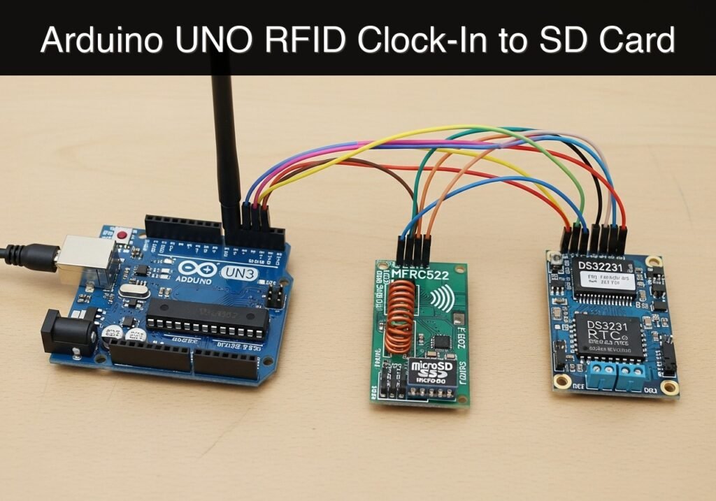
What you’ll build: A standalone hardware prototype that reads passive RFID tags, retrieves the current time from a precision real-time clock (RTC), and logs the event (UID and timestamp) to a CSV file on a microSD card.
Why it matters / Use cases
- Student Attendance Tracking: Automates classroom check-ins via ID card taps, eliminating manual roll calls.
- Lab Equipment Access Logging: Provides an offline audit trail of exactly who used a specific piece of machinery and at what time.
- Employee Time Clock: Acts as a basic punch-in/punch-out system for small workshops where network connectivity is unavailable.
- Security Auditing: Demonstrates the foundational principles of physical access control systems by logging entry attempts at a door or gate.
Expected outcome
- Successful initialization of shared SPI bus components (microSD and RFID) and I2C components (RTC).
- Serial monitor output displaying detected card UIDs and timestamps in real-time (< 100ms read latency).
- Creation of an
ATTEND.CSVfile on the microSD card containing properly formatted, comma-separated log entries.
Audience: Embedded systems developers and makers; Level: Intermediate
Architecture/flow: RFID Tag Tap → SPI RFID Reader → Microcontroller → I2C RTC Timestamp Fetch → SPI microSD CSV Append
Educational validation note
Before publication, this case passed the Prometeo automated validation gate with status PASS. The validator checked the code blocks, article structure, copy/paste-safe commands and consistency with the supported device catalog.
Published validation evidence
- Automatic result: PASS.
- Parsed structure: 3 sections, 5 tables and 2 code blocks detected before publication.
- Checked code: 2 Arduino/arduino-cli compile.
- Supported catalog: the article text was checked against Prometeo’s validation-capable device profiles, and unsupported stacks block publication.
- Report findings: no blocking findings.
This validation confirms syntax and tool compatibility for the published material, but it does not replace physical testing on your exact hardware, wiring and runtime environment.
Educational safety note
This project builds an educational prototype intended for learning hardware integration, SPI bus sharing, and data logging. It is not a secure access control system. The MIFARE Classic tags commonly used with the MFRC522 have well-documented cryptographic vulnerabilities and
Conceptual block diagram
High-level view: what enters the system, what each block processes, and what comes out.
Functional architecture
Conceptual signal and responsibility flow between device blocks.

Validation path
Conceptual summary of the tools used to check the published material.

Prerequisites
To successfully complete this tutorial, you need:
* Basic understanding of C++ programming and Arduino sketch structure (setup() and loop()).
* Familiarity with serial communication and reading serial monitor outputs.
* A computer with the arduino-cli (Arduino Command Line Interface) installed and added to your system path.
* A microSD card (32GB or smaller) formatted to FAT32.
* A USB Type-A to Type-B cable for programming and powering the Arduino UNO.
Materials
- Arduino UNO R3 (ATmega328P) + MFRC522 RFID module + microSD SPI module + DS3231 RTC (Exact target hardware).
- Passive RFID Tags or Cards (13.56 MHz, compatible with MFRC522, typically MIFARE Classic).
- Breadboard and premium male-to-male and male-to-female jumper wires.
- MicroSD card (formatted to FAT32).
Setup/Connection
This project requires careful wiring because two different modules (the MFRC522 and the microSD module) must share the Arduino’s single hardware SPI bus. The SPI bus uses shared lines for data (MOSI, MISO) and clock (SCK), but requires unique Chip Select (CS) pins for each device. The DS3231 RTC uses the I2C bus, which operates on separate pins.
Power Distribution Warning
- MFRC522: Must be powered by 3.3V. Applying 5V to the VCC pin of the MFRC522 will damage it.
- MicroSD Module: Most standard Arduino microSD modules have an onboard voltage regulator and level shifter. These should be powered by 5V.
- DS3231: Can safely operate at 5V.
Wiring Tables
1. MFRC522 RFID Module (SPI Bus 1 – 3.3V Logic)
| MFRC522 Pin | Arduino UNO R3 Pin | Function / Note |
|---|---|---|
| 3.3V | 3.3V | CRITICAL: Do not connect to 5V |
| RST | Pin 9 | Reset control |
| GND | GND | Common Ground |
| IRQ | Unconnected | Not used in this polling implementation |
| MISO | Pin 12 | Master In Slave Out (Shared SPI) |
| MOSI | Pin 11 | Master Out Slave In (Shared SPI) |
| SCK | Pin 13 | Serial Clock (Shared SPI) |
| SDA (CS) | Pin 10 | Chip Select for RFID |
2. MicroSD Card Module (SPI Bus 2 – 5V Logic)
| MicroSD Pin | Arduino UNO R3 Pin | Function / Note |
|---|---|---|
| VCC | 5V | Power for onboard regulator |
| GND | GND | Common Ground |
| MISO | Pin 12 | Master In Slave Out (Shared SPI) |
| MOSI | Pin 11 | Master Out Slave In (Shared SPI) |
| SCK | Pin 13 | Serial Clock (Shared SPI) |
| CS | Pin 4 | Chip Select for SD Card |
3. DS3231 RTC Module (I2C Bus)
| DS3231 Pin | Arduino UNO R3 Pin | Function / Note |
|---|---|---|
| VCC | 5V | Power |
| GND | GND | Common Ground |
| SDA | Pin A4 | I2C Data |
| SCL | Pin A5 | I2C Clock |
Validated Code
The project uses two separate code files. The first is a utility sketch to set the current date and time on your DS3231 RTC. The second is the main attendance logger application.
Utility Sketch: set_rtc_time.ino
Run this sketch once to program the RTC with your computer’s current compile time.
/*
 * Utility: Set DS3231 RTC Time
 * This sketch sets the RTC to the date & time the sketch was compiled.
 */

#include <Wire.h>
#include <RTClib.h>

RTC_DS3231 rtc;

void setup() {
  Serial.begin(9600);
  while (!Serial) { delay(10); } // Wait for serial console

  Serial.println("Initializing RTC...");

  if (!rtc.begin()) {
    Serial.println("Couldn't find RTC. Check wiring.");
    while (1) { delay(10); } // Halt
  }

  if (rtc.lostPower()) {
    Serial.println("RTC lost power, let's set the time!");
  }

  // Set the RTC to the date & time this sketch was compiled
  rtc.adjust(DateTime(F(__DATE__), F(__TIME__)));

  Serial.println("RTC time has been successfully updated!");
  Serial.print("Current time set to: ");

  DateTime now = rtc.now();
  Serial.print(now.year(), DEC);
  Serial.print('/');
  Serial.print(now.month(), DEC);
  Serial.print('/');
  Serial.print(now.day(), DEC);
  Serial.print(" ");
  Serial.print(now.hour(), DEC);
  Serial.print(':');
  Serial.print(now.minute(), DEC);
  Serial.print(':');
  Serial.println(now.second(), DEC);

  Serial.println("You can now flash the main attendance logger sketch.");
}

void loop() {
  // Nothing to do here
}
Main Application: attendance_logger.ino
This is the primary firmware for the prototype. It initializes the shared SPI bus, manages the Chip Select pins, polls for RFID cards, and appends records to the SD card.
Public preview of the validated file. The complete source is shown to members and in PDF/Print.
/*
 * Project: RFID Attendance SD Logger
 * Target: Arduino UNO R3 + MFRC522 + MicroSD + DS3231
 * Description: Reads RFID tag UIDs, fetches timestamp from RTC,
 *              and logs the data to ATTEND.CSV on the SD card.
 */

#include <SPI.h>
#include <MFRC522.h>
#include <SD.h>
#include <Wire.h>
#include <RTClib.h>

// --- Pin Definitions ---
#define SD_CS_PIN    4
#define RFID_CS_PIN  10
#define RFID_RST_PIN 9

// --- Object Instantiation ---
MFRC522 mfrc522(RFID_CS_PIN, RFID_RST_PIN);
RTC_DS3231 rtc;

// --- Global Variables ---
const char* logFileName = "ATTEND.CSV";

void setup() {
  // Initialize serial communications
  Serial.begin(9600);
  while (!Serial) { delay(10); } // Wait for serial port to connect

  Serial.println(F("--- RFID Attendance Logger Initialization ---"));

  // 1. Initialize SPI Bus
  SPI.begin();

  // 2. Initialize DS3231 RTC (I2C)
  if (!rtc.begin()) {
    Serial.println(F("ERROR: Couldn't find RTC."));
    while (1) { delay(10); }
  }
  if (rtc.lostPower()) {
    Serial.println(F("WARNING: RTC lost power. Time may be inaccurate."));
  } else {
    Serial.println(F("RTC initialized successfully."));
  }

  // 3. Initialize MicroSD Card (SPI)
  // Disable RFID SPI temporarily to ensure clean SD init
  pinMode(RFID_CS_PIN, OUTPUT);
  digitalWrite(RFID_CS_PIN, HIGH);

  Serial.print(F("Initializing SD card..."));
  if (!SD.begin(SD_CS_PIN)) {
    Serial.println(F("ERROR: SD card initialization failed!"));
    Serial.println(F("Check formatting (FAT32), wiring, and CS pin."));
    while (1) { delay(10); } // Halt if SD fails
  }
  Serial.println(F("SD card initialized."));

  // Write CSV Header if file doesn't exist
  if (!SD.exists(logFileName)) {
    File dataFile = SD.open(logFileName, FILE_WRITE);
    if (dataFile) {
      dataFile.println(F("Timestamp,UID"));
      dataFile.close();
      Serial.println(F("Created new ATTEND.CSV with headers."));
    } else {
      Serial.println(F("ERROR: Could not create file on SD card."));
    }
// .../*
* Project: RFID Attendance SD Logger
* Target: Arduino UNO R3 + MFRC522 + MicroSD + DS3231
* Description: Reads RFID tag UIDs, fetches timestamp from RTC,
* and logs the data to ATTEND.CSV on the SD card.
*/
#include <SPI.h>
#include <MFRC522.h>
#include <SD.h>
#include <Wire.h>
#include <RTClib.h>
// --- Pin Definitions ---
#define SD_CS_PIN 4
#define RFID_CS_PIN 10
#define RFID_RST_PIN 9
// --- Object Instantiation ---
MFRC522 mfrc522(RFID_CS_PIN, RFID_RST_PIN);
RTC_DS3231 rtc;
// --- Global Variables ---
const char* logFileName = "ATTEND.CSV";
void setup() {
// Initialize serial communications
Serial.begin(9600);
while (!Serial) { delay(10); } // Wait for serial port to connect
Serial.println(F("--- RFID Attendance Logger Initialization ---"));
// 1. Initialize SPI Bus
SPI.begin();
// 2. Initialize DS3231 RTC (I2C)
if (!rtc.begin()) {
Serial.println(F("ERROR: Couldn't find RTC."));
while (1) { delay(10); }
}
if (rtc.lostPower()) {
Serial.println(F("WARNING: RTC lost power. Time may be inaccurate."));
} else {
Serial.println(F("RTC initialized successfully."));
}
// 3. Initialize MicroSD Card (SPI)
// Disable RFID SPI temporarily to ensure clean SD init
pinMode(RFID_CS_PIN, OUTPUT);
digitalWrite(RFID_CS_PIN, HIGH);
Serial.print(F("Initializing SD card..."));
if (!SD.begin(SD_CS_PIN)) {
Serial.println(F("ERROR: SD card initialization failed!"));
Serial.println(F("Check formatting (FAT32), wiring, and CS pin."));
while (1) { delay(10); } // Halt if SD fails
}
Serial.println(F("SD card initialized."));
// Write CSV Header if file doesn't exist
if (!SD.exists(logFileName)) {
File dataFile = SD.open(logFileName, FILE_WRITE);
if (dataFile) {
dataFile.println(F("Timestamp,UID"));
dataFile.close();
Serial.println(F("Created new ATTEND.CSV with headers."));
} else {
Serial.println(F("ERROR: Could not create file on SD card."));
}
  }

  // 4. Initialize MFRC522 RFID (SPI)
  mfrc522.PCD_Init();
  // Optional: Increase antenna gain if tags are hard to read
  // mfrc522.PCD_SetAntennaGain(mfrc522.RxGain_max);
  Serial.println(F("MFRC522 initialized successfully."));

  Serial.println(F("--- System Ready. Waiting for RFID tags ---"));
}

void loop() {
  // Look for new RFID cards
  if (!mfrc522.PICC_IsNewCardPresent()) {
    return;
  }

  // Select one of the cards
  if (!mfrc522.PICC_ReadCardSerial()) {
    return;
  }

  // Get Current Time from RTC
  DateTime now = rtc.now();

  // Format Timestamp: YYYY-MM-DD HH:MM:SS
  char timeBuffer[20];
  snprintf(timeBuffer, sizeof(timeBuffer), "%04d-%02d-%02d %02d:%02d:%02d",
now.year(), now.month(), now.day(),
now.hour(), now.minute(), now.second());
// Format UID to Hex String
String uidString = "";
for (byte i = 0; i < mfrc522.uid.size; i++) {
if (mfrc522.uid.uidByte[i] < 0x10) {
uidString += "0";
}
uidString += String(mfrc522.uid.uidByte[i], HEX);
}
uidString.toUpperCase();
// Print to Serial Monitor
Serial.print(F("Scanned: "));
Serial.print(timeBuffer);
Serial.print(F(" | UID: "));
Serial.println(uidString);
// Log to SD Card
File dataFile = SD.open(logFileName, FILE_WRITE);
if (dataFile) {
dataFile.print(timeBuffer);
dataFile.print(F(","));
dataFile.println(uidString);
dataFile.close();
Serial.println(F(" -> Logged to SD card successfully."));
} else {
Serial.println(F(" -> ERROR: Failed to open ATTEND.CSV for writing."));
}
// Halt PICC to prevent reading the same card repeatedly in a single tap
mfrc522.PICC_HaltA();
// Stop encryption on PCD
mfrc522.PCD_StopCrypto1();
// Brief delay to prevent rapid-fire multiple reads
delay(1000);
}
Build/Flash/Run commands
Use the arduino-cli to compile and upload your code.
Command Reference Table
| Task | Command |
|---|---|
| Update core index | arduino-cli core update-index |
| Install AVR core | arduino-cli core install arduino:avr |
| Install dependencies | arduino-cli lib install "MFRC522" "RTClib" "SD" |
| Compile sketch | arduino-cli compile --fqbn arduino:avr:uno <Sketch_Folder> |
| Upload to UNO | arduino-cli upload --fqbn arduino:avr:uno --port <PORT> <Sketch_Folder> |
| Serial Monitor | arduino-cli monitor --port <PORT> --config baudrate=9600 |
Numbered Workflow
- Find your port: Connect the Arduino UNO to your computer. Run
arduino-cli board listto identify the<PORT>(e.g.,COM3on Windows,/dev/ttyACM0on Linux). - Install Libraries: Ensure the required third-party libraries are installed:
arduino-cli lib install "MFRC522" "RTClib" "SD" - Set the RTC Time:
- Save the first code block in a folder named
set_rtc_time. - Compile:
arduino-cli compile --fqbn arduino:avr:uno set_rtc_time - Upload:
arduino-cli upload --fqbn arduino:avr:uno --port <PORT> set_rtc_time - Monitor:
arduino-cli monitor --port <PORT> --config baudrate=9600to verify the time was set.
- Save the first code block in a folder named
- Flash the Main Logger:
- Save the second code block in a folder named
attendance_logger. - Compile:
arduino-cli compile --fqbn arduino:avr:uno attendance_logger - Upload:
arduino-cli upload --fqbn arduino:avr:uno --port <PORT> attendance_logger - Monitor:
arduino-cli monitor --port <PORT> --config baudrate=9600to view the live system.
- Save the second code block in a folder named
Step‑by‑step Validation
Use these checkpoints while monitoring the serial output to ensure your prototype is fully functional.
- Checkpoint: RTC Initialization
- Action: Reset the Arduino and watch the serial monitor.
- Expected observation: The monitor prints “RTC initialized successfully.”
- Pass condition: The system does not halt with “ERROR: Couldn’t find RTC.”
- Checkpoint: SD Card Mounting
- Action: Continue watching the serial monitor during boot.
- Expected observation: The monitor prints “Initializing SD card…” followed by “SD card initialized.”
- Pass condition: The system successfully mounts the FAT32 filesystem and does not halt.
- Checkpoint: RFID Module Initialization
- Action: Observe the final boot messages.
- Expected observation: The monitor prints “MFRC522 initialized successfully.” and “— System Ready. Waiting for RFID tags —“.
- Pass condition: Both SPI devices (SD and RFID) have initialized without causing bus conflicts.
- Checkpoint: Tag Scanning and Logging
- Action: Tap a 13.56 MHz RFID tag against the MFRC522 antenna.
- Expected observation: The serial monitor outputs “Scanned: [Date/Time] | UID: [Hex String]” followed by ” -> Logged to SD card successfully.”
- Pass condition: The UID matches your card, the timestamp is accurate, and the SD write reports success.
- Checkpoint: CSV Data Verification
- Action: Power down the Arduino, remove the microSD card, and read it on your computer.
- Expected observation: A file named
ATTEND.CSVexists. Opening it reveals a header row (Timestamp,UID) and a row for each card tap. - Pass condition: The data is properly comma-separated and human-readable in a spreadsheet application.
Troubleshooting
| Symptom | Likely cause | Fix |
|---|---|---|
Couldn't find RTC | I2C wiring issue. | Verify SDA is on A4 and SCL is on A5. Ensure the module has 5V and GND. |
SD card initialization failed! | Incorrect formatting or CS pin. | Ensure the SD card is formatted to FAT32 (not exFAT or NTFS). Verify CS is connected to Pin 4. |
| SD fails only when RFID is connected | SPI MISO conflict (Cheap SD modules). | Some SD modules do not release the MISO line when their CS is HIGH. Try powering the SD module from a separate 5V source or add a tri-state buffer to the SD MISO line. |
| RFID does not detect cards | Power supply or SPI wiring. | Ensure MFRC522 VCC is 3.3V, NOT 5V. Verify MOSI (11), MISO (12), SCK (13), SDA (10), and RST (9). |
| Timestamp is resetting to 2000-01-01 | RTC battery depleted. | Replace the CR2032 battery on the DS3231 module and re-run the set_rtc_time sketch. |
Improvements
Once the basic logger is working, consider these thematic enhancements for a more robust prototype:
- User Feedback Mechanisms:
- Add a piezoelectric buzzer to provide an audible “beep” upon a successful scan and log.
- Integrate a dual-color LED (Green for successful log, Red for SD card error) so the device can be used without a serial monitor attached.
- Data Management & Integrity:
- Implement a daily file rotation system (e.g.,
LOG_1024.CSVfor October 24) to prevent a single CSV file from becoming too large to parse quickly. - Add a known-UID database in the Arduino’s flash memory (using
PROGMEM) to reject unknown cards and only log authorized users.
- Implement a daily file rotation system (e.g.,
- Power and Deployment:
- Add a sleep mode routine to power down the SPI peripherals and put the ATmega328P to sleep when no card is present, waking via a hardware interrupt (if using a different RFID module that supports IRQ wake).
Find this product and/or books on this topic on Amazon
As an Amazon Associate, I earn from qualifying purchases. If you buy through this link, you help keep this project running.
Quick Quiz

Telecommunications Electronics Engineer and Computer Engineer (official degrees in Spain).

