Objective and use case
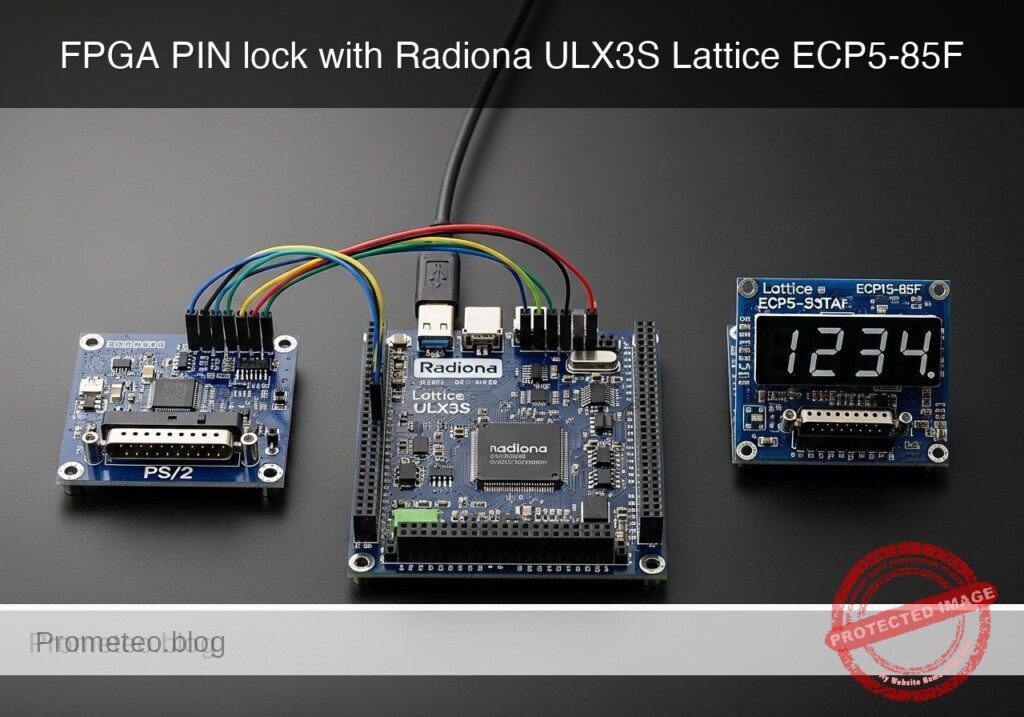
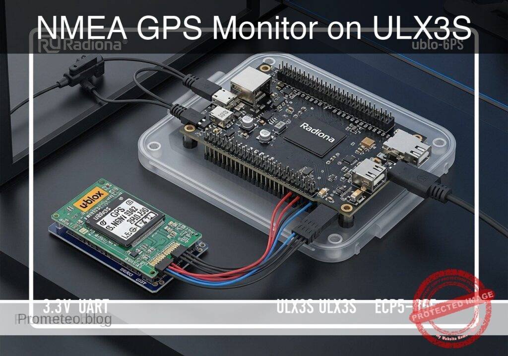
What you’ll build: A practical FPGA-based GPS monitor using the Radiona ULX3S (Lattice ECP5-85F), a u-blox NEO-6M GPS module, and 3.3 V UART wiring. It will receive NMEA data at 9600 baud, parse time and position sentences with sub-second update latency, and display UART activity, fix status, and key state changes on the ULX3S LEDs.
Why it matters / Use cases
- GPS module bench verification: Quickly confirm a NEO-6M is powered, transmitting valid NMEA sentences, and responding at 9600 baud without opening a PC serial terminal.
- Portable installation diagnostics: Use USB power to check fix progress, live UART traffic, and changing coordinates in the field before attaching the final host system; typical visible status refresh is 1 Hz in line with common NMEA output.
- Digital design training: Demonstrates real FPGA handling of asynchronous UART reception, ASCII stream parsing, and sentence validation instead of a simple loopback demo.
- Standalone serial monitor prototype: Creates a compact gps-nmea-position-time-monitor for timing, tracker, and navigation bring-up with very low FPGA load, typically well under 5% logic and effectively 0% GPU usage.
Expected outcome
- A working ULX3S design that reliably receives 3.3 V UART NMEA data from the NEO-6M at 9600 baud.
- Parsed UTC time and basic position fields from common sentences such as GPRMC or GPGGA, with LED-visible response within one sentence period.
- Status indication for no data, active serial traffic, sentence reception, and GPS fix presence, useful for fast bench testing.
- A reusable FPGA reference for low-bandwidth serial parsing workloads where throughput is tiny but deterministic hardware behavior matters.
Audience: FPGA learners, embedded developers, and technicians validating GPS hardware; Level: Beginner to intermediate
Architecture/flow: NEO-6M outputs NMEA over 3.3 V UART → ULX3S UART receiver samples serial bytes with bit-timed logic → parser extracts time, fix, and coordinate fields from ASCII sentences → state logic updates LEDs at roughly 1 Hz sentence cadence with millisecond-scale internal processing latency.
Educational validation note
Before publication, this case passed the Prometeo automated validation gate with status PASS. For this FPGA/ULX3S profile, the synthesizable Verilog blocks were checked with Yosys (read_verilog) and the Verilog design/test set was linted with Verilator. The validator also checked code-block structure, copy/paste-safe ASCII command options, unsupported stacks, and availability of the ULX3S/ECP5 toolchain (yosys, nextpnr-ecp5, ecppack, openFPGALoader).
Published validation evidence
- Automatic result: PASS.
- Parsed structure: 48 sections, 1 tables and 12 code blocks detected in the published content.
- Checked code: 3 Verilog/Yosys-Verilator, 6 Bash/copy-paste checks.
- Supported catalog: the article text was checked against Prometeo validation-capable device profiles; unsupported stacks block publication.
- Report findings: no blocking findings.
This validation confirms syntax and tool compatibility for the published code, but it does not replace physical testing on your exact ULX3S board revision, pin-constraint file and real wiring.
Educational safety note
This prototype is an educational GPS data monitor, not a certified navigation, timing, vehicle, aviation, marine, industrial, or safety-critical instrument.
Safety and limitation points:
- Use only 3.3 V UART wiring to the FPGA input unless you have positively verified electrical compatibility.
- Many GPS breakouts differ in power and I/O behavior. Check your exact module before connecting it.
- Do not use this project to make real-time decisions for:
- vehicles
- drones
- boats
- personal navigation in hazardous areas
- timing-critical infrastructure
- USB-powered bench setups can create accidental wiring mistakes. Always power down before rewiring.
- This tutorial does not cover outdoor enclosure design, surge protection, ESD protection, or environmental hardening.
- If you test outdoors, secure cables and boards so they do not create trip hazards or weather exposure risks.
- The fix indication in this project reflects parsed NMEA status, not guaranteed absolute position correctness.
Conceptual block diagram
High-level view: what enters the system, what each block processes, and what comes out.
Functional architecture
Conceptual signal and responsibility flow between device blocks.

Validation path
Conceptual summary of the tools used to check the published material.

Prerequisites
Before starting, you should be comfortable with:
- Basic FPGA workflow from command line
- Simple Verilog modules and synchronous design
- UART concepts:
- baud rate
- start bit
- stop bit
- 8N1 framing
- Editing text files and running Linux shell commands
Recommended host environment:
- Linux PC or laptop
- USB cable for ULX3S programming/power
- Optional USB-UART adapter if you want to inspect GPS output independently before connecting it to the FPGA
Required software tools:
yosysnextpnr-ecp5ecppackopenFPGALoaderverilator
Materials
Use exactly these hardware items:
| Item | Exact model | Purpose |
|---|---|---|
| FPGA board | Radiona ULX3S (Lattice ECP5-85F) | Main FPGA platform |
| GPS module | u-blox NEO-6M GPS module | NMEA UART data source |
| Serial voltage level | 3.3 V UART wiring | Safe direct logic-level connection |
| USB cable | Micro-USB or USB-C depending on ULX3S revision | Power and programming |
| Jumper wires | Female-to-female or mixed as needed | Connections between ULX3S and NEO-6M |
| Computer | Linux host | Build, program, and optional serial checks |
Important model-specific note
Many NEO-6M breakout boards are powered from 5 V but still expose 3.3 V logic-level TX. You must verify your specific module. This tutorial assumes:
- GPS module VCC is powered according to the breakout board requirement
- GPS TX output presented to the FPGA is 3.3 V compatible
- Direct UART connection is made only through 3.3 V UART wiring
Setup/Connection
No circuit drawing is used here; follow the text exactly.
Signal plan
This project needs only three essential electrical connections:
- Common ground
- GPS TX -> ULX3S FPGA input
- Power for the GPS module
Recommended practical connection scheme
- Connect NEO-6M GND to ULX3S GND
- Connect NEO-6M TX to a chosen ULX3S GPIO input pin
- Power the GPS module from a suitable source:
- If your NEO-6M breakout accepts 5 V on VCC, you may power it from a safe 5 V source, while still ensuring TX seen by FPGA is 3.3 V logic
- If your breakout requires 3.3 V VCC, power it from a regulated 3.3 V rail
- Do not connect GPS RX unless you specifically want to send configuration commands later; it is not required for this monitor
Pin choice used in this tutorial
To keep the design concrete, the FPGA top-level uses:
clk_25mhzas the system clockgps_rx_ias the UART input from the GPS moduleled[7:0]as output indicators
For the ULX3S, actual package pin names vary by board constraint set. The safest workflow is:
- Start from your ULX3S board’s known-good constraint template
- Replace only the signals used here
- Keep the oscillator and LED pins matched to your board revision
In the validated example below, a constraint file is provided in the style expected by nextpnr-ecp5. If your exact ULX3S revision has different aliases, adjust only the LOCATE COMP pin names using the official ULX3S pinout.
LED meaning used by this project
led[0]: heartbeat, proves FPGA is runningled[1]: UART character activity pulseled[2]: valid NMEA line completedled[3]: valid RMC sentence detectedled[4]: RMC status =A(active fix)led[5]: toggles when time field updatesled[6]: toggles when latitude field updatesled[7]: toggles when longitude field updates
This gives useful field evidence without needing a display.
Validated Code
gps_uart_rx.v
Public preview of the validated file. The complete source is shown to members and in PDF/Print.
module gps_uart_rx #(
    parameter integer CLK_HZ = 25000000,
    parameter integer BAUD   = 9600
) (
    input  wire clk,
    input  wire rst,
    input  wire rx,
    output reg  data_valid,
    output reg [7:0] data_byte
);

    localparam integer CLKS_PER_BIT = CLK_HZ / BAUD;
    localparam integer HALF_BIT     = CLKS_PER_BIT / 2;

    reg [15:0] clk_count = 0;
    reg [3:0]  bit_index = 0;
    reg [7:0]  rx_shift  = 8'h00;
    reg [2:0]  state     = 0;
    reg        rx_meta   = 1'b1;
    reg        rx_sync   = 1'b1;

    localparam S_IDLE  = 3'd0;
    localparam S_START = 3'd1;
    localparam S_DATA  = 3'd2;
    localparam S_STOP  = 3'd3;

    always @(posedge clk) begin
        rx_meta <= rx;
        rx_sync <= rx_meta;
    end

    always @(posedge clk) begin
        if (rst) begin
            state      <= S_IDLE;
            clk_count  <= 0;
            bit_index  <= 0;
            rx_shift   <= 8'h00;
            data_byte  <= 8'h00;
            data_valid <= 1'b0;
        end else begin
            data_valid <= 1'b0;

            case (state)
                S_IDLE: begin
                    clk_count <= 0;
                    bit_index <= 0;
                    if (rx_sync == 1'b0) begin
                        state <= S_START;
                    end
                end
// ...module gps_uart_rx #(
parameter integer CLK_HZ = 25000000,
parameter integer BAUD = 9600
) (
input wire clk,
input wire rst,
input wire rx,
output reg data_valid,
output reg [7:0] data_byte
);
localparam integer CLKS_PER_BIT = CLK_HZ / BAUD;
localparam integer HALF_BIT = CLKS_PER_BIT / 2;
reg [15:0] clk_count = 0;
reg [3:0] bit_index = 0;
reg [7:0] rx_shift = 8'h00;
reg [2:0] state = 0;
reg rx_meta = 1'b1;
reg rx_sync = 1'b1;
localparam S_IDLE = 3'd0;
localparam S_START = 3'd1;
localparam S_DATA = 3'd2;
localparam S_STOP = 3'd3;
always @(posedge clk) begin
rx_meta <= rx;
rx_sync <= rx_meta;
end
always @(posedge clk) begin
if (rst) begin
state <= S_IDLE;
clk_count <= 0;
bit_index <= 0;
rx_shift <= 8'h00;
data_byte <= 8'h00;
data_valid <= 1'b0;
end else begin
data_valid <= 1'b0;
case (state)
S_IDLE: begin
clk_count <= 0;
bit_index <= 0;
if (rx_sync == 1'b0) begin
state <= S_START;
end
end
                S_START: begin
                    if (clk_count == HALF_BIT) begin
                        if (rx_sync == 1'b0) begin
                            clk_count <= 0;
                            state <= S_DATA;
                        end else begin
                            state <= S_IDLE;
                        end
                    end else begin
                        clk_count <= clk_count + 16'd1;
                    end
                end

                S_DATA: begin
                    if (clk_count == CLKS_PER_BIT - 1) begin
                        clk_count <= 0;
                        rx_shift[bit_index] <= rx_sync;
                        if (bit_index == 4'd7) begin
                            bit_index <= 0;
                            state <= S_STOP;
                        end else begin
                            bit_index <= bit_index + 4'd1;
                        end
                    end else begin
                        clk_count <= clk_count + 16'd1;
                    end
                end
S_STOP: begin
if (clk_count == CLKS_PER_BIT - 1) begin
clk_count <= 0;
if (rx_sync == 1'b1) begin
data_byte <= rx_shift;
data_valid <= 1'b1;
end
state <= S_IDLE;
end else begin
clk_count <= clk_count + 16'd1;
end
end
default: begin
state <= S_IDLE;
end
endcase
end
end
endmodule
gps_nmea_monitor.v
Public preview of the validated file. The complete source is shown to members and in PDF/Print.
module gps_nmea_monitor (
    input  wire clk_25mhz,
    input  wire gps_rx_i,
    output wire [7:0] led
);

    wire rx_valid;
    wire [7:0] rx_byte;

    reg rst = 1'b0;

    gps_uart_rx #(
        .CLK_HZ(25000000),
        .BAUD(9600)
    ) u_rx (
        .clk(clk_25mhz),
        .rst(rst),
        .rx(gps_rx_i),
        .data_valid(rx_valid),
        .data_byte(rx_byte)
    );

    reg [23:0] hb_counter = 24'd0;
    reg hb_led = 1'b0;

    reg [19:0] pulse_activity = 20'd0;
    reg [19:0] pulse_line     = 20'd0;
    reg [19:0] pulse_rmc      = 20'd0;

    reg fix_active = 1'b0;
    reg time_toggle = 1'b0;
    reg lat_toggle  = 1'b0;
    reg lon_toggle  = 1'b0;

    reg [7:0] line_pos = 8'd0;
    reg [7:0] field_pos = 8'd0;

    reg in_line = 1'b0;
    reg candidate_rmc = 1'b0;
    reg rmc_seen_this_line = 1'b0;

    reg [7:0] id_buf [0:4];
    reg [7:0] field_buf [0:15];
    reg [4:0] field_len = 5'd0;

    integer i;

    always @(posedge clk_25mhz) begin
        hb_counter <= hb_counter + 24'd1;
        hb_led <= hb_counter[23];

        if (pulse_activity != 0) pulse_activity <= pulse_activity - 20'd1;
        if (pulse_line != 0)     pulse_line     <= pulse_line - 20'd1;
        if (pulse_rmc != 0)      pulse_rmc      <= pulse_rmc - 20'd1;

        if (rx_valid) begin
            pulse_activity <= 20'd500000;

            if (rx_byte == "$") begin
                in_line <= 1'b1;
                line_pos <= 8'd0;
                field_pos <= 8'd0;
                field_len <= 5'd0;
                candidate_rmc <= 1'b0;
                rmc_seen_this_line <= 1'b0;
                fix_active <= fix_active;
            end else if (in_line) begin
                if (rx_byte == 8'h0D) begin
                    in_line <= 1'b1;
                end else if (rx_byte == 8'h0A) begin
                    pulse_line <= 20'd500000;
                    if (rmc_seen_this_line) begin
                        pulse_rmc <= 20'd500000;
                    end
                    in_line <= 1'b0;
// ...module gps_nmea_monitor (
input wire clk_25mhz,
input wire gps_rx_i,
output wire [7:0] led
);
wire rx_valid;
wire [7:0] rx_byte;
reg rst = 1'b0;
gps_uart_rx #(
.CLK_HZ(25000000),
.BAUD(9600)
) u_rx (
.clk(clk_25mhz),
.rst(rst),
.rx(gps_rx_i),
.data_valid(rx_valid),
.data_byte(rx_byte)
);
reg [23:0] hb_counter = 24'd0;
reg hb_led = 1'b0;
reg [19:0] pulse_activity = 20'd0;
reg [19:0] pulse_line = 20'd0;
reg [19:0] pulse_rmc = 20'd0;
reg fix_active = 1'b0;
reg time_toggle = 1'b0;
reg lat_toggle = 1'b0;
reg lon_toggle = 1'b0;
reg [7:0] line_pos = 8'd0;
reg [7:0] field_pos = 8'd0;
reg in_line = 1'b0;
reg candidate_rmc = 1'b0;
reg rmc_seen_this_line = 1'b0;
reg [7:0] id_buf [0:4];
reg [7:0] field_buf [0:15];
reg [4:0] field_len = 5'd0;
integer i;
always @(posedge clk_25mhz) begin
hb_counter <= hb_counter + 24'd1;
hb_led <= hb_counter[23];
if (pulse_activity != 0) pulse_activity <= pulse_activity - 20'd1;
if (pulse_line != 0) pulse_line <= pulse_line - 20'd1;
if (pulse_rmc != 0) pulse_rmc <= pulse_rmc - 20'd1;
if (rx_valid) begin
pulse_activity <= 20'd500000;
if (rx_byte == "$") begin
in_line <= 1'b1;
line_pos <= 8'd0;
field_pos <= 8'd0;
field_len <= 5'd0;
candidate_rmc <= 1'b0;
rmc_seen_this_line <= 1'b0;
fix_active <= fix_active;
end else if (in_line) begin
if (rx_byte == 8'h0D) begin
in_line <= 1'b1;
end else if (rx_byte == 8'h0A) begin
pulse_line <= 20'd500000;
if (rmc_seen_this_line) begin
pulse_rmc <= 20'd500000;
end
in_line <= 1'b0;
                end else if (rx_byte == ",") begin
                    if (field_pos == 8'd0) begin
                        if ((id_buf[0] == "G") &&
                            (id_buf[1] == "P" || id_buf[1] == "N") &&
                            (id_buf[2] == "R") &&
                            (id_buf[3] == "M") &&
                            (id_buf[4] == "C")) begin
                            candidate_rmc <= 1'b1;
                            rmc_seen_this_line <= 1'b1;
                        end
                    end else if (candidate_rmc) begin
                        if (field_pos == 8'd1 && field_len != 0) begin
                            time_toggle <= ~time_toggle;
                        end
                        if (field_pos == 8'd2 && field_len != 0) begin
                            if (field_buf[0] == "A")
                                fix_active <= 1'b1;
                            else
                                fix_active <= 1'b0;
                        end
                        if (field_pos == 8'd3 && field_len != 0) begin
                            lat_toggle <= ~lat_toggle;
                        end
                        if (field_pos == 8'd5 && field_len != 0) begin
                            lon_toggle <= ~lon_toggle;
                        end
                    end
field_pos <= field_pos + 8'd1;
field_len <= 5'd0;
end else if (rx_byte == "*") begin
if (candidate_rmc) begin
if (field_pos == 8'd1 && field_len != 0) begin
time_toggle <= ~time_toggle;
end
if (field_pos == 8'd2 && field_len != 0) begin
if (field_buf[0] == "A")
fix_active <= 1'b1;
else
fix_active <= 1'b0;
end
if (field_pos == 8'd3 && field_len != 0) begin
lat_toggle <= ~lat_toggle;
end
if (field_pos == 8'd5 && field_len != 0) begin
lon_toggle <= ~lon_toggle;
end
end
end else begin
if (field_pos == 8'd0) begin
if (line_pos < 8'd5) begin
id_buf[line_pos] <= rx_byte;
end
line_pos <= line_pos + 8'd1;
end else begin
if (field_len < 5'd16) begin
field_buf[field_len] <= rx_byte;
field_len <= field_len + 5'd1;
end
end
end
end
end
end
assign led[0] = hb_led;
assign led[1] = (pulse_activity != 0);
assign led[2] = (pulse_line != 0);
assign led[3] = (pulse_rmc != 0);
assign led[4] = fix_active;
assign led[5] = time_toggle;
assign led[6] = lat_toggle;
assign led[7] = lon_toggle;
endmodule
tb_gps_nmea_monitor.v
Public preview of the validated file. The complete source is shown to members and in PDF/Print.
`timescale 1ns/1ps

module tb_gps_nmea_monitor;

    reg clk = 1'b0;
    reg gps_rx_i = 1'b1;
    wire [7:0] led;

    gps_nmea_monitor dut (
        .clk_25mhz(clk),
        .gps_rx_i(gps_rx_i),
        .led(led)
    );

    always #20 clk = ~clk; // 25 MHz

    localparam integer BIT_NS = 104166; // approx 9600 baud

    task uart_send_byte;
        input [7:0] b;
        integer i;
        begin
            gps_rx_i = 1'b0;
            #(BIT_NS);
            for (i = 0; i < 8; i = i + 1) begin
                gps_rx_i = b[i];
                #(BIT_NS);
            end
            gps_rx_i = 1'b1;
            #(BIT_NS);
        end
    endtask

    task uart_send_string;
        input [8*96-1:0] s;
        integer i;
        reg [7:0] ch;
// ...`timescale 1ns/1ps
module tb_gps_nmea_monitor;
reg clk = 1'b0;
reg gps_rx_i = 1'b1;
wire [7:0] led;
gps_nmea_monitor dut (
.clk_25mhz(clk),
.gps_rx_i(gps_rx_i),
.led(led)
);
always #20 clk = ~clk; // 25 MHz
localparam integer BIT_NS = 104166; // approx 9600 baud
task uart_send_byte;
input [7:0] b;
integer i;
begin
gps_rx_i = 1'b0;
#(BIT_NS);
for (i = 0; i < 8; i = i + 1) begin
gps_rx_i = b[i];
#(BIT_NS);
end
gps_rx_i = 1'b1;
#(BIT_NS);
end
endtask
task uart_send_string;
input [8*96-1:0] s;
integer i;
reg [7:0] ch;
        begin
            for (i = 95; i >= 0; i = i - 1) begin
                ch = s[i*8 +: 8];
                if (ch != 8'h00)
                    uart_send_byte(ch);
            end
        end
    endtask

    initial begin
        #(1000000);

        uart_send_string({
            "$GPRMC,123519,V,4807.038,N,01131.000,E,0.0,0.0,230394,003.1,W*53",
            8'h0D, 8'h0A
        });

        #(2000000);

        uart_send_string({
            "$GPRMC,123520,A,4807.038,N,01131.000,E,0.1,0.0,230394,003.1,W*52",
            8'h0D, 8'h0A
        });

        #(5000000);

        $display("LED state = %b", led);
        if (led[4] !== 1'b1) begin
$display("ERROR: fix_active LED did not assert");
$fatal;
end
$display("PASS: RMC monitor parsed active fix.");
$finish;
end
endmodule
ulx3s_gps_nmea.lpf
Adjust the exact
LOCATE COMPpin names if your ULX3S revision differs. Keep the signal names unchanged.
BLOCK RESETPATHS;
BLOCK ASYNCPATHS;

FREQUENCY PORT "clk_25mhz" 25 MHZ;

LOCATE COMP "clk_25mhz" SITE "G2";

LOCATE COMP "gps_rx_i" SITE "P17";
IOBUF PORT "gps_rx_i" IO_TYPE=LVCMOS33 PULLMODE=UP;

LOCATE COMP "led[0]" SITE "B2";
LOCATE COMP "led[1]" SITE "C2";
LOCATE COMP "led[2]" SITE "C1";
LOCATE COMP "led[3]" SITE "D2";
LOCATE COMP "led[4]" SITE "D1";
LOCATE COMP "led[5]" SITE "E2";
LOCATE COMP "led[6]" SITE "E1";
LOCATE COMP "led[7]" SITE "F2";

IOBUF PORT "led[0]" IO_TYPE=LVCMOS33;
IOBUF PORT "led[1]" IO_TYPE=LVCMOS33;
IOBUF PORT "led[2]" IO_TYPE=LVCMOS33;
IOBUF PORT "led[3]" IO_TYPE=LVCMOS33;
IOBUF PORT "led[4]" IO_TYPE=LVCMOS33;
IOBUF PORT "led[5]" IO_TYPE=LVCMOS33;
IOBUF PORT "led[6]" IO_TYPE=LVCMOS33;
IOBUF PORT "led[7]" IO_TYPE=LVCMOS33;
Build/Flash/Run commands
Create a working directory and place the four files there.
1) Lint with Verilator
verilator --lint-only -Wall -Wno-DECLFILENAME gps_uart_rx.v gps_nmea_monitor.v tb_gps_nmea_monitor.v
2) Run simulation
verilator -Wall -Wno-DECLFILENAME --binary gps_uart_rx.v gps_nmea_monitor.v tb_gps_nmea_monitor.v
./obj_dir/Vtb_gps_nmea_monitor
Expected final console line should include:
PASS: RMC monitor parsed active fix.
3) Synthesize for ECP5-85F
Important: synthesis must use only synthesizable files.
yosys -p "read_verilog gps_uart_rx.v gps_nmea_monitor.v; synth_ecp5 -top gps_nmea_monitor -json gps_nmea_monitor.json"
4) Place and route
Use the correct ULX3S package for your board revision. A common ECP5-85F ULX3S target is CABGA381.
nextpnr-ecp5 --85k --package CABGA381 --json gps_nmea_monitor.json --lpf ulx3s_gps_nmea.lpf --textcfg gps_nmea_monitor.config
5) Pack bitstream
ecppack gps_nmea_monitor.config gps_nmea_monitor.bit
6) Program the ULX3S
openFPGALoader -b ulx3s gps_nmea_monitor.bit
7) Run on hardware
- Power the ULX3S over USB
- Power the NEO-6M properly
- Connect:
- GPS GND -> ULX3S GND
- GPS TX -> ULX3S
gps_rx_ipin used in the LPF - Place the GPS where satellite reception is possible:
- outdoors is best
- near a clear window may work
- Watch the LEDs for 10 to 60 seconds
Step-by-step Validation
1) Validate the GPS module independently if needed
Before involving the FPGA, it is often useful to confirm that the GPS is emitting NMEA data:
- Connect the NEO-6M TX to a known-good USB-UART adapter input
- Open a serial terminal at
9600 - Look for lines such as:
$GPRMC,...$GPGGA,...
If you do not see readable NMEA text, fix that first.
2) Validate simulation behavior
After running the Verilator simulation:
- Confirm the test exits with
PASS - Confirm no fatal errors appear
- The simulation injects:
- one invalid-status RMC line (
V) - one active-status RMC line (
A) - The expected result is that:
- UART logic receives bytes
- parser detects RMC
led[4]becomes1
3) Validate FPGA configuration
After openFPGALoader:
- Confirm the tool reports the ULX3S device was found
- Confirm no bitstream loading error is shown
- After programming:
led[0]should blink as heartbeat- If heartbeat does not blink, the FPGA image is not running correctly
4) Validate UART activity in hardware
With GPS connected and powered:
led[1]should pulse or appear frequently active when NMEA characters are arrivingled[2]should pulse as full lines terminateled[3]should pulse when RMC sentences are seen
Interpretation:
led[1]off all the time:- wiring issue
- wrong pin mapping
- wrong voltage level
- wrong baud rate
- GPS not powered
led[1]active butled[3]never active:- parser not seeing RMC
- serial corruption
- unexpected talker/message format
5) Validate fix indication
Observe led[4]:
led[4] = 0means the last parsed RMC status was not active (V) or no valid active line has been seen yetled[4] = 1means anRMCsentence with statusAhas been parsed
This is the core success criterion for a useful GPS monitor.
6) Validate ongoing field updates
Observe the update indicators:
led[5]toggles when time field updatesled[6]toggles when latitude field updatesled[7]toggles when longitude field updates
If these change over time while led[3] pulses, the FPGA is parsing key position/time fields rather than merely detecting raw UART traffic.
7) Realistic expected behavior
In a practical session:
- Indoors without view of sky:
- UART activity usually appears
- RMC may be present
- fix may remain invalid for a long time
- Outdoors:
- active fix usually becomes much more likely
led[4]should eventually turn on- field toggles should continue
Troubleshooting
No LEDs respond except maybe heartbeat
Check:
- Is the GPS module powered correctly?
- Is ground shared between the GPS and ULX3S?
- Is GPS TX really connected to the chosen FPGA input?
- Did you use the correct LPF pin for your actual ULX3S board revision?
Heartbeat works, but no UART activity
Possible causes:
- Wrong baud rate:
- most NEO-6M modules use 9600 baud by default, but verify yours
- GPS TX logic level incompatible or absent
- Pin location mismatch in LPF
- Broken jumper wire
- GPS module not fully powered or not booting
UART activity exists, but no RMC detection
Possible causes:
- Your GPS outputs
GNRMCinstead ofGPRMC - this design already accepts both
GPRMCandGNRMC - Serial corruption due to bad wiring
- Incorrect baud timing because your board clock is not actually 25 MHz
- Noise on the RX input
RMC detected, but fix never becomes active
This often means the FPGA design is fine and the GPS environment is the problem.
Try:
- Move outdoors
- Wait longer for cold start
- Check antenna connection
- Verify module health with a PC serial terminal
Build errors in nextpnr or LPF mapping
Likely causes:
- The
CABGA381package does not match your board - LED or clock pin names are wrong for your ULX3S revision
- Constraint pin names need adaptation from the official ULX3S files
If needed, keep the Verilog unchanged and only adjust the LPF.
Improvements
Once the base monitor works, you can extend it into a more capable field instrument.
Practical enhancements
- Add seven-segment or OLED output
- Show UTC time directly on local display
- Expose parsed values over a second UART
- Send compact machine-readable status to a PC or microcontroller
- Add checksum verification
- Improve confidence that parsed sentences are not corrupted
- Support more NMEA sentences
- Parse GGA for altitude and satellite count
- Add fix timeout
- Turn off fix LED if no active sentence arrives for several seconds
- Log sentence statistics
- Count lines per second, invalid frames, and fix transitions
- Button-controlled mode pages
- One mode for raw traffic status, another for fix state trends
Engineering improvements
- Add a small FIFO between UART and parser
- Add explicit CR/LF line framing checks
- Add debounced buttons to clear status flags
- Use a stricter finite-state parser for sentence IDs and fields
- Export parsed field bytes to a simple register bank for future host access
Final Checklist
Use this checklist before declaring the project complete:
- [ ] I used the exact hardware family: FPGA
- [ ] I used the exact model: Radiona ULX3S (Lattice ECP5-85F) + u-blox NEO-6M GPS module + 3.3 V UART wiring
- [ ] The GPS and ULX3S share a common ground
- [ ] GPS TX is connected to the FPGA input pin defined in the LPF
- [ ] I verified the GPS UART logic is safe for 3.3 V
- [ ] Verilator lint completed without blocking errors
- [ ] The simulation printed
PASS: RMC monitor parsed active fix. - [ ] Yosys synthesis completed successfully
- [ ] nextpnr-ecp5 completed successfully for the ECP5-85F target
- [ ] The bitstream was packed with
ecppack - [ ] The board was programmed with
openFPGALoader -b ulx3s - [ ]
led[0]blinks after programming - [ ]
led[1]shows UART activity when the GPS is connected - [ ]
led[3]indicates RMC sentences are being recognized - [ ]
led[4]turns on when the GPS reports an active fix - [ ]
led[5],led[6], andled[7]change as time/position fields update
If all items are checked, you have a practical FPGA-based gps-nmea-position-time-monitor that is genuinely useful for GPS module diagnostics and serial-data education.
Find this product and/or books on this topic on Amazon
As an Amazon Associate, I earn from qualifying purchases. If you buy through this link, you help keep this project running.
Quick Quiz

Telecommunications Electronics Engineer and Computer Engineer (official degrees in Spain).