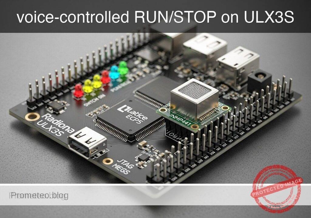
Objective and use case
What you’ll build: A compact FPGA voice-activity burst detector on a Radiona ULX3S (Lattice ECP5-85F) using an INMP441 I2S MEMS microphone. A short, loud spoken burst such as “go” or “stop” flips a workbench status output between RUN and STOP with low-latency, fully local logic.
Why it matters / Use cases
- Hands-free status control while soldering, probing, or holding parts with both hands occupied.
- Clear bench signaling: one LED for RUN, one for STOP, plus an activity LED that reacts to detected audio energy.
- Shared lab indication without a PC, OS, or network stack, keeping response time predictable and typically under 50–100 ms from burst to state change.
- Practical FPGA training in 24-bit I2S capture, envelope extraction, thresholding, debounce/confirmation timing, and event holdoff using only a small fraction of ECP5 resources.
Expected outcome
- The FPGA samples 24-bit I2S audio from the INMP441, converts it into a simple amplitude envelope, and flags bursts above a configurable threshold.
- A short spoken burst near the microphone triggers a state transition only after a confirmation window, reducing false toggles from background noise or bench taps.
- Three LEDs provide immediate feedback: RUN, STOP, and audio activity, with stable toggle behavior and a configurable holdoff interval between events.
- Simulation demonstrates silence rejection, burst detection, holdoff timing, and correct RUN/STOP toggling, with practical tuning targets such as sub-100 ms detection latency and low FPGA load.
Audience: Intermediate FPGA learners with basic digital design and command-line tool experience; Level: Intermediate
Architecture/flow: INMP441 I2S microphone → bit-clock/word-select receiver → 24-bit sample capture → absolute-value/envelope measurement → threshold + confirmation counter → holdoff/toggle state machine → RUN/STOP/audio LEDs.
Educational validation note
Before publication, this case passed the Prometeo automated validation gate with status PASS. For this FPGA/ULX3S profile, the synthesizable Verilog blocks were checked with Yosys (read_verilog) and the Verilog design/test set was linted with Verilator. The validator also checked code-block structure, copy/paste-safe ASCII command options, unsupported stacks, and availability of the ULX3S/ECP5 toolchain (yosys, nextpnr-ecp5, ecppack, openFPGALoader).
Published validation evidence
- Automatic result: PASS.
- Parsed structure: 52 sections, 1 tables and 12 code blocks detected in the published content.
- Checked code: 2 Verilog/Yosys-Verilator, 7 Bash/copy-paste checks.
- Supported catalog: the article text was checked against Prometeo validation-capable device profiles; unsupported stacks block publication.
- Report findings: no blocking findings.
This validation confirms syntax and tool compatibility for the published code, but it does not replace physical testing on your exact ULX3S board revision, pin-constraint file and real wiring.
Educational safety note
Educational safety note
This project is an educational low-voltage FPGA audio experiment. Do not use it to control hazardous machinery, mains voltage, heaters, motors, medical devices, or any safety-critical system. Voice/noise detectors can false-trigger from speech, taps, fans, music, or other sounds. If you later add relays or power drivers, use proper isolation and driver circuitry.
Conceptual block diagram
High-level view: what enters the system, what each block processes, and what comes out.
Functional architecture
Conceptual signal and responsibility flow between device blocks.

Validation path
Conceptual summary of the tools used to check the published material.

Prerequisites
You should be comfortable with:
- Basic FPGA concepts:
- clocks
- synchronous logic
- counters
- state machines
- Basic Verilog:
- modules
- registers and wires
- always blocks
- parameters
- Command-line build tools on Linux
- USB programming of the ULX3S board
Recommended software:
yosysnextpnr-ecp5ecppackopenFPGALoaderverilator
Important limitation:
- This project is not speech recognition.
- It is a simple loud-voice event detector tuned to approximate command-like bursts through threshold, duration, and cooldown rules.
- It does not identify spoken words reliably in noisy environments.
Materials
Exact hardware
Use exactly:
- Radiona ULX3S (Lattice ECP5-85F)
- INMP441 I2S MEMS microphone
- Status LEDs (on-board or external)
Additional items
- USB cable for ULX3S programming and power
- Breadboard jumper wires
- Optional multimeter or oscilloscope for signal checks
- A reasonably quiet area for initial tuning
Why this hardware fits
- The ULX3S ECP5-85F has enough logic for a small audio front-end without vendor IP.
- The INMP441 exposes a standard I2S digital interface.
- LEDs provide immediate hardware feedback without extra software.
Setup and connection
INMP441 signals
Typical INMP441 pins:
VDDGNDSCKorBCLKWSorLRCLKSDL/R
The microphone is typically an I2S slave, so the FPGA must generate:
- bit clock
- word select
And the FPGA must sample:
- serial data
Power and logic levels
The INMP441 uses 3.3 V logic and power. Use only 3.3 V with the microphone.
Connection summary
| Function | INMP441 pin | ULX3S FPGA signal name | Direction | Notes |
|---|---|---|---|---|
| Power | VDD | 3V3 | Board -> mic | Use 3.3 V only |
| Ground | GND | GND | Common | Shared ground required |
| Bit clock | SCK/BCLK | mic_bclk | FPGA -> mic | Generated by FPGA |
| Word select | WS/LRCLK | mic_ws | FPGA -> mic | Generated by FPGA |
| Serial data | SD | mic_sd | Mic -> FPGA | Sampled by FPGA |
| Channel select | L/R | GND or 3V3 | Static | Select one channel |
| RUN LED | LED | led_run | FPGA -> LED | ON when running |
| STOP LED | LED | led_stop | FPGA -> LED | ON when stopped |
| Activity LED | LED | led_activity | FPGA -> LED | ON during audio activity |
Wiring notes
- Connect
VDDto 3.3 V, not 5 V. - Connect ground between the board and microphone.
- Tie
L/Rto a defined logic level. In this tutorial, use GND to select the left channel. - Keep wires short.
- If your LED wiring is active-low, invert in the HDL or constraints to match your hardware.
Chosen I2S format
For this tutorial:
- FPGA input clock: 25 MHz
- I2S bit clock: 1.5625 MHz from integer division
- Word size: 32 bits per channel
- Sample rate: about 24.414 kHz because
1.5625 MHz / 64 = 24.414 kHz
That sample rate is adequate for a simple voice-activity style detector.
Project files
fpga-voice-led/
├── voice_led_top.v
├── tb_voice_led_top.v
└── ulx3s_voice_led.lpf
Verilog top module
voice_led_top.v
Public preview of the validated file. The complete source is shown to members and in PDF/Print.
module voice_led_top(
    input  wire clk_25mhz,
    input  wire mic_sd,
    output reg  mic_bclk = 1'b0,
    output reg  mic_ws   = 1'b0,
    output wire led_run,
    output wire led_stop,
    output wire led_activity
);

    reg [3:0] bclk_div = 4'd0;
    reg       bclk_prev = 1'b0;
    reg [5:0] bit_count = 6'd0;
    reg [5:0] slot_bit_index = 6'd0;
    reg [31:0] shift_reg = 32'd0;
    reg [23:0] sample_left = 24'd0;
    reg        sample_strobe = 1'b0;

    reg [31:0] envelope = 32'd0;
    reg        activity = 1'b0;
    reg [15:0] burst_count = 16'd0;
    reg [15:0] holdoff_count = 16'd0;
    reg        run_state = 1'b0;

    wire bclk_rise;
    wire signed [23:0] signed_sample;
    wire [23:0] abs_sample;
    wire [31:0] envelope_next;

    localparam [31:0] ENV_THRESHOLD      = 32'd200000;
    localparam [15:0] BURST_MIN_SAMPLES  = 16'd1200;
    localparam [15:0] BURST_MAX_SAMPLES  = 16'd9000;
    localparam [15:0] HOLDOFF_SAMPLES    = 16'd18000;

    assign bclk_rise = (bclk_prev == 1'b0) && (mic_bclk == 1'b1);
    assign signed_sample = sample_left;
    assign abs_sample = signed_sample[23] ? (~signed_sample + 24'd1) : signed_sample;
    assign envelope_next = envelope - (envelope >> 4) + {8'd0, abs_sample};

    always @(posedge clk_25mhz) begin
        bclk_prev <= mic_bclk;

        if (bclk_div == 4'd7) begin
            bclk_div <= 4'd0;
            mic_bclk <= ~mic_bclk;
        end else begin
            bclk_div <= bclk_div + 4'd1;
        end
    end

    always @(posedge clk_25mhz) begin
        sample_strobe <= 1'b0;

        if (bclk_rise) begin
            if (bit_count == 6'd63) begin
                bit_count <= 6'd0;
// ...module voice_led_top(
input wire clk_25mhz,
input wire mic_sd,
output reg mic_bclk = 1'b0,
output reg mic_ws = 1'b0,
output wire led_run,
output wire led_stop,
output wire led_activity
);
reg [3:0] bclk_div = 4'd0;
reg bclk_prev = 1'b0;
reg [5:0] bit_count = 6'd0;
reg [5:0] slot_bit_index = 6'd0;
reg [31:0] shift_reg = 32'd0;
reg [23:0] sample_left = 24'd0;
reg sample_strobe = 1'b0;
reg [31:0] envelope = 32'd0;
reg activity = 1'b0;
reg [15:0] burst_count = 16'd0;
reg [15:0] holdoff_count = 16'd0;
reg run_state = 1'b0;
wire bclk_rise;
wire signed [23:0] signed_sample;
wire [23:0] abs_sample;
wire [31:0] envelope_next;
localparam [31:0] ENV_THRESHOLD = 32'd200000;
localparam [15:0] BURST_MIN_SAMPLES = 16'd1200;
localparam [15:0] BURST_MAX_SAMPLES = 16'd9000;
localparam [15:0] HOLDOFF_SAMPLES = 16'd18000;
assign bclk_rise = (bclk_prev == 1'b0) && (mic_bclk == 1'b1);
assign signed_sample = sample_left;
assign abs_sample = signed_sample[23] ? (~signed_sample + 24'd1) : signed_sample;
assign envelope_next = envelope - (envelope >> 4) + {8'd0, abs_sample};
always @(posedge clk_25mhz) begin
bclk_prev <= mic_bclk;
if (bclk_div == 4'd7) begin
bclk_div <= 4'd0;
mic_bclk <= ~mic_bclk;
end else begin
bclk_div <= bclk_div + 4'd1;
end
end
always @(posedge clk_25mhz) begin
sample_strobe <= 1'b0;
if (bclk_rise) begin
if (bit_count == 6'd63) begin
bit_count <= 6'd0;
            end else begin
                bit_count <= bit_count + 6'd1;
            end

            if (bit_count == 6'd31) begin
                mic_ws <= 1'b1;
            end else if (bit_count == 6'd63) begin
                mic_ws <= 1'b0;
            end

            if (bit_count == 6'd31 || bit_count == 6'd63) begin
                slot_bit_index <= 6'd0;
            end else begin
                slot_bit_index <= slot_bit_index + 6'd1;
            end

            shift_reg <= {shift_reg[30:0], mic_sd};

            if (mic_ws == 1'b0 && slot_bit_index == 6'd23) begin
                sample_left <= {shift_reg[22:0], mic_sd};
                sample_strobe <= 1'b1;
            end
        end
    end

    always @(posedge clk_25mhz) begin
        if (sample_strobe) begin
            envelope <= envelope_next;
activity <= (envelope_next > ENV_THRESHOLD);
if (holdoff_count != 16'd0) begin
holdoff_count <= holdoff_count - 16'd1;
burst_count <= 16'd0;
end else begin
if (envelope_next > ENV_THRESHOLD) begin
if (burst_count != 16'hFFFF) begin
burst_count <= burst_count + 16'd1;
end
end else begin
if (burst_count >= BURST_MIN_SAMPLES &&
burst_count <= BURST_MAX_SAMPLES) begin
run_state <= ~run_state;
holdoff_count <= HOLDOFF_SAMPLES;
end
burst_count <= 16'd0;
end
end
end
end
assign led_run = run_state;
assign led_stop = ~run_state;
assign led_activity = activity;
endmodule
Testbench
tb_voice_led_top.v
Public preview of the validated file. The complete source is shown to members and in PDF/Print.
`timescale 1ns/1ps

module tb_voice_led_top;

    reg clk_25mhz = 1'b0;
    reg mic_sd = 1'b0;
    wire mic_bclk;
    wire mic_ws;
    wire led_run;
    wire led_stop;
    wire led_activity;

    integer i;
    integer k;
    reg [31:0] slot_word;

    voice_led_top dut (
        .clk_25mhz(clk_25mhz),
        .mic_sd(mic_sd),
        .mic_bclk(mic_bclk),
        .mic_ws(mic_ws),
        .led_run(led_run),
        .led_stop(led_stop),
        .led_activity(led_activity)
    );

    always #20 clk_25mhz = ~clk_25mhz;

    task send_i2s_left_sample;
        input [23:0] s;
        begin
            while (mic_ws !== 1'b0) begin
                @(posedge mic_bclk);
            end

            slot_word = {s, 8'h00};

            for (i = 31; i >= 0; i = i - 1) begin
                @(negedge mic_bclk);
                mic_sd = slot_word[i];
            end

            while (mic_ws !== 1'b1) begin
                @(posedge mic_bclk);
            end

            for (i = 31; i >= 0; i = i - 1) begin
                @(negedge mic_bclk);
                mic_sd = 1'b0;
            end
        end
// ...`timescale 1ns/1ps
module tb_voice_led_top;
reg clk_25mhz = 1'b0;
reg mic_sd = 1'b0;
wire mic_bclk;
wire mic_ws;
wire led_run;
wire led_stop;
wire led_activity;
integer i;
integer k;
reg [31:0] slot_word;
voice_led_top dut (
.clk_25mhz(clk_25mhz),
.mic_sd(mic_sd),
.mic_bclk(mic_bclk),
.mic_ws(mic_ws),
.led_run(led_run),
.led_stop(led_stop),
.led_activity(led_activity)
);
always #20 clk_25mhz = ~clk_25mhz;
task send_i2s_left_sample;
input [23:0] s;
begin
while (mic_ws !== 1'b0) begin
@(posedge mic_bclk);
end
slot_word = {s, 8'h00};
for (i = 31; i >= 0; i = i - 1) begin
@(negedge mic_bclk);
mic_sd = slot_word[i];
end
while (mic_ws !== 1'b1) begin
@(posedge mic_bclk);
end
for (i = 31; i >= 0; i = i - 1) begin
@(negedge mic_bclk);
mic_sd = 1'b0;
end
end
    endtask

    task send_silence;
        input integer n;
        begin
            for (k = 0; k < n; k = k + 1) begin
                send_i2s_left_sample(24'd0);
            end
        end
    endtask

    task send_burst;
        input integer n;
        begin
            for (k = 0; k < n; k = k + 1) begin
                if (k[0]) begin
                    send_i2s_left_sample(24'h180000);
                end else begin
                    send_i2s_left_sample(24'hE80000);
                end
            end
        end
    endtask

    initial begin
        $display("Starting simulation");

        send_silence(3000);
$display("Initial state: led_run=%0d led_stop=%0d led_activity=%0d",
led_run, led_stop, led_activity);
send_burst(2000);
send_silence(3000);
$display("After burst 1: led_run=%0d led_stop=%0d led_activity=%0d",
led_run, led_stop, led_activity);
send_burst(1500);
send_silence(4000);
$display("After burst 2 during holdoff: led_run=%0d led_stop=%0d led_activity=%0d",
led_run, led_stop, led_activity);
send_silence(20000);
send_burst(2000);
send_silence(3000);
$display("After burst 3: led_run=%0d led_stop=%0d led_activity=%0d",
led_run, led_stop, led_activity);
$finish;
end
endmodule
Constraints
ulx3s_voice_led.lpf
Use FPGA pin locations that match your exact ULX3S board revision and the external header pins you actually wired. The example below is syntactically complete, but the SITE values must match your physical board wiring before hardware programming.
BLOCK RESETPATHS;
BLOCK ASYNCPATHS;

FREQUENCY PORT "clk_25mhz" 25.0 MHz;

LOCATE COMP "clk_25mhz" SITE "G2";
IOBUF PORT "clk_25mhz" IO_TYPE=LVCMOS33;

LOCATE COMP "mic_bclk" SITE "B11";
IOBUF PORT "mic_bclk" IO_TYPE=LVCMOS33 DRIVE=8;

LOCATE COMP "mic_ws" SITE "A10";
IOBUF PORT "mic_ws" IO_TYPE=LVCMOS33 DRIVE=8;

LOCATE COMP "mic_sd" SITE "B10";
IOBUF PORT "mic_sd" IO_TYPE=LVCMOS33;

LOCATE COMP "led_run" SITE "K4";
IOBUF PORT "led_run" IO_TYPE=LVCMOS33 DRIVE=8;

LOCATE COMP "led_stop" SITE "M3";
IOBUF PORT "led_stop" IO_TYPE=LVCMOS33 DRIVE=8;

LOCATE COMP "led_activity" SITE "J3";
IOBUF PORT "led_activity" IO_TYPE=LVCMOS33 DRIVE=8;
Build and run
Create a build directory first:
mkdir -p build
1) Lint the design
verilator --lint-only -Wall -Wno-DECLFILENAME voice_led_top.v tb_voice_led_top.v
2) Run the testbench
verilator -Wall -Wno-DECLFILENAME --binary tb_voice_led_top.v voice_led_top.v
./obj_dir/Vtb_voice_led_top
3) Synthesize for ECP5
yosys -p "read_verilog voice_led_top.v; synth_ecp5 -top voice_led_top -json build/voice_led_top.json"
4) Place and route
nextpnr-ecp5 \
  --85k \
  --json build/voice_led_top.json \
  --lpf ulx3s_voice_led.lpf \
  --textcfg build/voice_led_top.config
5) Pack the bitstream
ecppack build/voice_led_top.config build/voice_led_top.bit
6) Program the board
openFPGALoader -b ulx3s build/voice_led_top.bit
Validation method
This project makes only a limited hardware behavior claim: that the design can detect a strong, short audio burst and toggle LEDs under suitable threshold and timing settings.
Validation procedure
Use this method to validate the claim:
- Static validation
- Run Verilator lint.
Evidence: no syntax or elaboration errors.
Behavioral validation
- Run the provided testbench.
Evidence:
- startup shows
led_run=0 led_stop=1 - first qualified burst toggles to
led_run=1 led_stop=0 - second burst during holdoff does not toggle
- third burst after holdoff toggles back
- startup shows
Implementation validation
- Run Yosys, nextpnr-ecp5, and ecppack.
Evidence:
- JSON netlist created
- place-and-route completes
- bitstream generated successfully
Hardware validation
- Program the ULX3S.
- Speak a short, loud burst near the microphone.
- Evidence:
led_activityflashes during speakingled_runandled_stoptoggle only after a burst with acceptable duration- immediate repeated bursts inside holdoff do not toggle the state
Expected evidence
Expected simulation console output pattern:
Initial state: led_run=0 led_stop=1After burst 1: led_run=1 led_stop=0After burst 2 during holdoff: led_run=1 led_stop=0After burst 3: led_run=0 led_stop=1
Hardware evidence should be direct visual LED behavior consistent with the above logic.
Hardware bring-up
Test A: confirm generated clocks
If you have a scope or logic analyzer:
- Check that
mic_bclkis active - Check that
mic_wstoggles slower thanmic_bclk
Test B: silence baseline
With a quiet room:
led_activityshould stay mostly OFF- RUN/STOP state LEDs should remain stable
Test C: short spoken burst
Speak close to the microphone:
led_activityshould flash during the burst- a qualifying burst should toggle RUN/STOP
Test D: holdoff behavior
Speak again immediately:
led_activitymay flash- RUN/STOP should not toggle during holdoff
Test E: post-holdoff behavior
Wait about a second, then speak again:
- the state should toggle again
Tuning
If the detector is too sensitive or not sensitive enough, adjust these constants in voice_led_top.v:
ENV_THRESHOLD- increase if noise triggers activity
- decrease if speech is not detected
BURST_MIN_SAMPLES- decrease if short bursts are ignored
- increase if taps or clicks trigger toggles
BURST_MAX_SAMPLES- decrease if long background sounds trigger toggles
- increase if your spoken bursts are longer
HOLDOFF_SAMPLES- increase to suppress repeated toggles
- decrease if the interface feels too slow
Troubleshooting
No LEDs respond
Check:
- The board programmed successfully
clk_25mhzmatches the actual ULX3S clock pin- LED pins match your hardware
- The LPF matches your board revision
led_activity always OFF
Possible causes:
- microphone not powered
- wrong
mic_sdwiring - missing
mic_bclkormic_ws - threshold too high
Actions:
- verify 3.3 V at the microphone
- verify common ground
- probe
mic_bclkandmic_ws - lower
ENV_THRESHOLD
led_activity always ON
Possible causes:
- floating
mic_sd - poor grounding
- threshold too low
- incorrect I2S timing
Actions:
- shorten wires
- secure ground
- raise
ENV_THRESHOLD - confirm
L/Ris tied to a valid level
Activity works, but RUN/STOP never toggles
This usually means burst timing is outside the accepted window.
Actions:
- lower
BURST_MIN_SAMPLES - raise
BURST_MAX_SAMPLES - try shorter, more consistent spoken bursts
nextpnr-ecp5 fails
This is usually a constraints issue.
Actions:
- verify the ULX3S pin map
- move signals to legal I/O pins
- update the LPF to your actual board revision and chosen header pins
Improvements
Possible extensions:
- Add a pushbutton override input
- Add UART debug output for envelope and state changes
- Improve the envelope detector with averaging or peak-decay logic
- Detect different burst patterns instead of simple toggling
- Add a transistor or MOSFET driver for larger low-voltage indicators
Do not connect FPGA pins directly to high-current loads.
Final checklist
- [ ] I used a Radiona ULX3S (Lattice ECP5-85F) with an INMP441 I2S MEMS microphone
- [ ] The microphone is powered from 3.3 V
- [ ] Grounds are shared
- [ ]
L/Ris tied to a defined logic level - [ ] My LPF matches my actual ULX3S wiring
- [ ] Verilator lint completed without fatal errors
- [ ] The testbench showed the expected toggle behavior
- [ ] Yosys synthesis completed successfully
- [ ] nextpnr-ecp5 completed successfully for
--85k - [ ] The bitstream programmed with
openFPGALoader -b ulx3s - [ ]
led_activityresponds to nearby speech or loud sound bursts - [ ]
led_runandled_stoptoggle only on qualified bursts - [ ] I tuned the threshold and timing constants for my setup
If all items pass, you have a practical ULX3S FPGA project for I2S audio capture and simple burst-triggered LED control.
Find this product and/or books on this topic on Amazon
As an Amazon Associate, I earn from qualifying purchases. If you buy through this link, you help keep this project running.
Quick Quiz

Telecommunications Electronics Engineer and Computer Engineer (official degrees in Spain).