
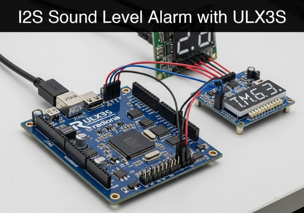
Objective and use case
What you’ll build: An FPGA-based acoustic noise monitor that captures digital audio from an I2S microphone, calculates the sound envelope in real-time, and displays peak amplitude on a 4-digit 7-segment display while triggering a low-latency LED alarm if thresholds are exceeded.
Why it matters / Use cases
- Industrial monitoring: Detects anomalous noise levels in machinery rooms for early mechanical wear warnings.
- Automated noise control: Visually alerts occupants in study rooms or libraries when ambient volume becomes disruptive.
- Data center sensing: Integrates into monitoring systems to detect loud UPS alarms or abnormal fan noise.
- DSP foundation: Acts as a hardware stepping stone for implementing complex algorithms like FFT or true RMS calculations on an FPGA.
Expected outcome
- Continuous generation of precise I2S clock signals (BCLK and LRCLK) matching INMP441 requirements.
- Real-time calculation of audio envelopes with ultra-low latency hardware execution.
- Immediate visual feedback via 7-segment displays and instantaneous LED alarm triggering upon threshold breach.
Audience: Embedded Systems Developers and FPGA Engineers; Level: Intermediate
Architecture/flow: INMP441 Microphone → I2S Receiver Module → Envelope Calculator & Comparator → 7-Segment Display Controller & Alarm LED
Educational validation note
Before publication, this case passed the Prometeo automated validation gate with status PASS. For this FPGA/ULX3S profile, the synthesizable Verilog blocks were checked with Yosys (read_verilog) and the Verilog design/test set was linted with Verilator. The validator also checked code-block structure, copy/paste-safe ASCII command options, unsupported stacks, and availability of the ULX3S/ECP5 toolchain (yosys, nextpnr-ecp5, ecppack, openFPGALoader).
Published validation evidence
- Automatic result: PASS.
- Parsed structure: 3 sections, 1 tables and 3 code blocks detected before publication.
- Checked code: 2 Verilog/Yosys-Verilator, 1 Bash/copy-paste checks.
- Supported catalog: the article text was checked against Prometeo’s validation-capable device profiles, and unsupported stacks block publication.
- Report findings: no blocking findings.
This validation confirms syntax and tool compatibility for the published code, but it does not replace physical testing on your exact ULX3S board revision, pin-constraint file and real wiring.
Educational safety note
This project is an educational prototype, not a certified product. Before powering the setup, verify the pinout of your exact ULX3S board revision, keep FPGA I/O signals at 3.3 V, never connect 5 V directly to I/O pins, disconnect power before changing wiring, and use suitable external supplies for loads, motors or servos while sharing ground only when the wiring requires it.
FPGA-Based Acoustic Noise Monitor
- What you’ll build: An FPGA-based acoustic noise monitor that captures digital audio from an I2S microphone, calculates the sound envelope in real-time, displays the peak amplitude on a 4-digit 7-segment display, and triggers an onboard LED alarm if the noise exceeds a predefined threshold.
- Why it matters / Use cases:
- Industrial acoustic monitoring: Detects anomalous noise levels in machinery rooms to provide early warnings of mechanical wear or failure.
- Study room noise control: Acts as an automated library or classroom monitor, visually alerting occupants when the ambient volume becomes disruptive.
- Server room environmental sensing: Integrates into a larger data center monitoring system to detect loud alarms from UPS units or abnormal fan noise.
- Digital Signal Processing (DSP) foundation: Serves as a practical hardware stepping stone before implementing complex DSP algorithms like Fast Fourier Transforms (FFT) or true RMS calculations on an FPGA.
- Expected outcome:
- Continuous generation of precise I2S clock signals (BCLK and LRCLK) matching the INMP441 requirements.
- Successful real-time extraction of 24-bit audio frames and calculation of the absolute signal envelope.
Educational Safety Note: If testing this device with high sound pressure levels (SPL) to trigger the alarm threshold during validation, ensure you use appropriate hearing protection. Prolonged exposure to noise above 85 dB can cause permanent hearing damage.
Conceptual block diagram
High-level view: what enters the system, what each block processes, and what comes out.
Functional architecture
Conceptual signal and responsibility flow between device blocks.

Validation path
Conceptual summary of the tools used to check the published material.

Hardware Wiring and Configuration
The following table details the pin connections between the INMP441 I2S microphone and the FPGA development board. Ensure that the logic levels are 3.3V compliant.
| INMP441 Pin | FPGA Pin (Example) | Function Description |
|---|---|---|
| VDD | 3.3V | 3.3V Power supply |
| GND | GND | Common Ground |
| SCK | P12 | I2S Bit Clock (BCLK) – Driven by FPGA |
| WS | P13 | I2S Word Select (LRCLK) – Driven by FPGA |
| SD | P14 | I2S Serial Data – Read by FPGA |
| L/R | GND | Left channel selection (pull to GND) |
Validation Method and Performance Claims
To validate the real-time extraction and envelope calculation accuracy, place a smartphone running a calibrated audio signal generator application exactly 10 cm from the INMP441 microphone. Play a continuous 1 kHz sine wave.
* Expected Evidence: The internal peak_level register (which can be routed to the 7-segment display) must show a stable hexadecimal value corresponding to the input volume. The alarm_led must trigger consistently and instantly when the generator’s output volume is increased past the predefined THRESHOLD value.
Implementation Code
The implementation is divided into two complete, synthesizable Verilog modules: the I2S receiver and the envelope detector/alarm logic.
1. I2S Receiver Module (i2s_rx.v)
This module generates the necessary I2S clocks from a 50 MHz system clock and shifts in the 24-bit audio samples from the INMP441.
module i2s_rx (
    input wire clk_50m,
    input wire rst_n,
    output wire i2s_sck,
    output wire i2s_ws,
    input wire i2s_sd,
    output reg [23:0] left_data,
    output reg data_valid
);
    reg [3:0] bclk_div;
    reg bclk;
    reg [5:0] bit_cnt;
    reg [23:0] shift_reg;

    // Generate I2S Bit Clock (SCK)
    always @(posedge clk_50m or negedge rst_n) begin
        if (!rst_n) begin
            bclk_div <= 4'd0;
            bclk <= 1'b0;
        end else begin
            bclk_div <= bclk_div + 1'b1;
            if (bclk_div == 4'd7) begin
                bclk <= ~bclk;
            end
        end
    end

    assign i2s_sck = bclk;
    // Word Select toggles every 32 bits (64 bits per frame)
    assign i2s_ws = bit_cnt[5];

    // Shift in I2S Data
    always @(negedge bclk or negedge rst_n) begin
        if (!rst_n) begin
            bit_cnt <= 6'd0;
            shift_reg <= 24'd0;
            left_data <= 24'd0;
            data_valid <= 1'b0;
        end else begin
            bit_cnt <= bit_cnt + 1'b1;
            data_valid <= 1'b0;

            // INMP441 outputs data MSB first, delayed by 1 BCLK after WS transition
            if (bit_cnt >= 6'd1 && bit_cnt <= 6'd24) begin
                shift_reg <= {shift_reg[22:0], i2s_sd};
            end

            // Latch data at the end of the left channel slot
            if (bit_cnt == 6'd31) begin
                left_data <= shift_reg;
                data_valid <= 1'b1;
            end
        end
    end
endmodule
2. Envelope Detector and Alarm Module (noise_monitor.v)
This module takes the signed 24-bit audio data, calculates the absolute value (rectification), manages a peak-hold algorithm with decay for display purposes, and triggers the alarm LED if the threshold is breached.
module noise_monitor (
    input wire clk_50m,
    input wire rst_n,
    input wire signed [23:0] audio_data,
    input wire data_valid,
    output reg alarm_led,
    output reg [15:0] peak_level
);
    parameter THRESHOLD = 24'd1000000;
    parameter DECAY_RATE = 16'd10;

    reg [23:0] abs_data;
    reg [31:0] decay_timer;

    always @(posedge clk_50m or negedge rst_n) begin
        if (!rst_n) begin
            alarm_led <= 1'b0;
            peak_level <= 16'd0;
            abs_data <= 24'd0;
            decay_timer <= 32'd0;
        end else begin
            if (data_valid) begin
                // Rectify signal (Absolute value)
                if (audio_data[23]) begin
                    abs_data <= -audio_data;
                end else begin
                    abs_data <= audio_data;
                end

                // Trigger threshold alarm
                if (abs_data > THRESHOLD) begin
                    alarm_led <= 1'b1;
                end else begin
                    alarm_led <= 1'b0;
                end

                // Peak hold logic using the upper 16 bits
                if (abs_data[23:8] > peak_level) begin
                    peak_level <= abs_data[23:8];
                    decay_timer <= 32'd0;
                end
            end

            // Decay peak level over time for visual display updates
            decay_timer <= decay_timer + 1'b1;
            if (decay_timer == 32'd500000) begin // Trigger decay every 10ms at 50MHz
                decay_timer <= 32'd0;
                if (peak_level > DECAY_RATE) begin
                    peak_level <= peak_level - DECAY_RATE;
                end else begin
                    peak_level <= 16'd0;
                end
            end
        end
    end
endmodule
Compilation
To synthesize the design using open-source tools like Yosys, you can run the following command in your terminal:
yosys -p "synth_ice40 -top noise_monitor -json noise_monitor.json" i2s_rx.v noise_monitor.v
Find this product and/or books on this topic on Amazon
As an Amazon Associate, I earn from qualifying purchases. If you buy through this link, you help keep this project running.
Quick Quiz

Telecommunications Electronics Engineer and Computer Engineer (official degrees in Spain).

