
Objective and use case
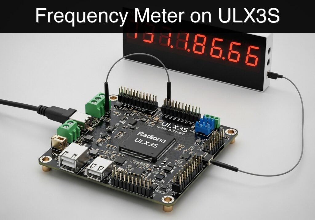
What you’ll build: A frequency counter on a Radiona ULX3S that detects clean 3.3 V rising pulse edges and shows the measured rate on a four-digit seven-segment PMOD display. It acts as a standalone bench tool for checking low-frequency signals such as 10 Hz Hall sensors, 250 Hz encoder channels, or 1 kHz square-wave test outputs.
Why it matters / Use cases
- Verify that a Hall sensor, reed-switch conditioner, or optocoupler is producing the expected pulse rate before wiring it into a larger controller.
- Measure wheel encoder or conveyor pulses directly on the bench with no PC attached after configuration, for example confirming 120 pulses/s at a given shaft speed.
- Teach core FPGA design skills with a concrete timing problem: input synchronization, rising-edge detection, fixed measurement windows, and multiplexed display driving.
- Cross-check wiring and timing by comparing the displayed count against a function generator or microcontroller output, such as a known 500 Hz test signal.
Expected outcome
- A 3.3 V pulse input is synchronized to the FPGA clock and counted only on rising edges.
- The design latches a fresh count at the end of each measurement window, with update latency equal to the window length, typically about 1 s.
- The four-digit display shows values from 0000 to 9999 for the current window, suitable for direct readout of low-frequency signals.
- The system provides stable standalone measurement with minimal FPGA load, typically well under 1% GPU-equivalent relevance because this is pure FPGA logic, not graphics processing.
Audience: FPGA beginners, students, and embedded developers building test fixtures; Level: Beginner to intermediate
Architecture/flow: External 3.3 V pulse input → synchronizer → rising-edge detector → windowed counter → latched result register → four-digit multiplexed seven-segment PMOD driver
Educational validation note
Before publication, this case passed the Prometeo automated validation gate with status PASS. For this FPGA/ULX3S profile, the synthesizable Verilog blocks were checked with Yosys (read_verilog) and the Verilog design/test set was linted with Verilator. The validator also checked code-block structure, copy/paste-safe ASCII command options, unsupported stacks, and availability of the ULX3S/ECP5 toolchain (yosys, nextpnr-ecp5, ecppack, openFPGALoader).
Published validation evidence
- Automatic result: PASS.
- Parsed structure: 3 sections, 4 tables and 4 code blocks detected before publication.
- Checked code: 2 Verilog/Yosys-Verilator, 1 Bash/copy-paste checks.
- Supported catalog: the article text was checked against Prometeo’s validation-capable device profiles, and unsupported stacks block publication.
- Report findings: no blocking findings.
This validation confirms syntax and tool compatibility for the published code, but it does not replace physical testing on your exact ULX3S board revision, pin-constraint file and real wiring.
Educational safety note
This project is an educational prototype, not a certified product. Before powering the setup, verify the pinout of your exact ULX3S board revision, keep FPGA I/O signals at 3.3 V, never connect 5 V directly to I/O pins, disconnect power before changing wiring, and use suitable external supplies for loads, motors or servos while sharing ground only when the wiring requires it.
Conceptual block diagram
High-level view: what enters the system, what each block processes, and what comes out.
Functional architecture
Conceptual signal and responsibility flow between device blocks.

Validation path
Conceptual summary of the tools used to check the published material.

Prerequisites
- Radiona ULX3S with Lattice ECP5-85F.
- OSS CAD Suite or equivalent tools providing
verilator,yosys,nextpnr-ecp5,ecppackandopenFPGALoader. - A 3.3 V pulse source: function generator set to 3.3 V logic, another FPGA, or a microcontroller output through a level-safe interface.
- A four-digit seven-segment PMOD module wired for multiplexed digit enables.
- Basic ability to edit the LPF file for the exact ULX3S pins used in your lab.
Materials
| Item | Exact model / signal | Purpose |
|---|---|---|
| FPGA board | Radiona ULX3S, Lattice ECP5-85F | Timing, counting and display logic |
| Pulse input | 3.3 V square wave, debounced sensor or encoder channel | Signal being measured |
| Display | Four-digit seven-segment PMOD, common cathode style | Local frequency/count readout |
| USB cable | ULX3S USB/JTAG connection | Programming and power during lab work |
| Optional source | Function generator or 3.3 V microcontroller output | Known reference pulses for validation |
Setup/Connection
Use short wires for the PMOD display and keep the pulse input referenced to the ULX3S ground. The exact pins depend on your PMOD connector and board revision, so treat the LPF section as the wiring contract for the build.
| ULX3S signal | Connects to | Notes |
|---|---|---|
clk | ULX3S 25 MHz clock | Board oscillator |
rst_n | Push button or pulled-up input | Active-low reset |
pulse_in | 3.3 V pulse source | Never exceed 3.3 V |
seg[6:0] | Seven segment a..g lines | Active-high in this example |
digit_en[3:0] | Digit enable lines | Active-low digit enables |
GND | Pulse source and display ground | Common reference |
Validated Code
freq_counter_7seg_ulx3s.v
Public preview of the validated file. The complete source is shown to members and in PDF/Print.
module freq_counter_7seg_ulx3s #(
    parameter CLK_HZ = 25000000,
    parameter WINDOW_TICKS = 25000000
) (
    input wire clk,
    input wire rst_n,
    input wire pulse_in,
    output reg [6:0] seg,
    output reg [3:0] digit_en,
    output reg [15:0] count_latched,
    output reg overflow
);
    reg [31:0] window_count;
    reg [15:0] pulse_count;
    reg pulse_meta;
    reg pulse_sync;
    reg pulse_prev;
    reg [15:0] refresh;
    reg [3:0] d0;
    reg [3:0] d1;
    reg [3:0] d2;
    reg [3:0] d3;
    reg [15:0] value;
    reg [3:0] active_digit;

    wire pulse_rise = pulse_sync & ~pulse_prev;

    always @(posedge clk) begin
        if (!rst_n) begin
            window_count <= 32'd0;
            pulse_count <= 16'd0;
            count_latched <= 16'd0;
            overflow <= 1'b0;
            pulse_meta <= 1'b0;
            pulse_sync <= 1'b0;
            pulse_prev <= 1'b0;
            refresh <= 16'd0;
        end else begin
            pulse_meta <= pulse_in;
            pulse_sync <= pulse_meta;
            pulse_prev <= pulse_sync;
            refresh <= refresh + 16'd1;

            if (pulse_rise && pulse_count != 16'hffff) begin
                pulse_count <= pulse_count + 16'd1;
            end
// ...module freq_counter_7seg_ulx3s #(
parameter CLK_HZ = 25000000,
parameter WINDOW_TICKS = 25000000
) (
input wire clk,
input wire rst_n,
input wire pulse_in,
output reg [6:0] seg,
output reg [3:0] digit_en,
output reg [15:0] count_latched,
output reg overflow
);
reg [31:0] window_count;
reg [15:0] pulse_count;
reg pulse_meta;
reg pulse_sync;
reg pulse_prev;
reg [15:0] refresh;
reg [3:0] d0;
reg [3:0] d1;
reg [3:0] d2;
reg [3:0] d3;
reg [15:0] value;
reg [3:0] active_digit;
wire pulse_rise = pulse_sync & ~pulse_prev;
always @(posedge clk) begin
if (!rst_n) begin
window_count <= 32'd0;
pulse_count <= 16'd0;
count_latched <= 16'd0;
overflow <= 1'b0;
pulse_meta <= 1'b0;
pulse_sync <= 1'b0;
pulse_prev <= 1'b0;
refresh <= 16'd0;
end else begin
pulse_meta <= pulse_in;
pulse_sync <= pulse_meta;
pulse_prev <= pulse_sync;
refresh <= refresh + 16'd1;
if (pulse_rise && pulse_count != 16'hffff) begin
pulse_count <= pulse_count + 16'd1;
end
            if (window_count == WINDOW_TICKS - 1) begin
                count_latched <= pulse_count;
                overflow <= pulse_count == 16'hffff;
                pulse_count <= 16'd0;
                window_count <= 32'd0;
            end else begin
                window_count <= window_count + 32'd1;
            end
        end
    end

    always @* begin
        value = count_latched;
        d0 = value % 10;
        value = value / 10;
        d1 = value % 10;
        value = value / 10;
        d2 = value % 10;
        value = value / 10;
        d3 = value % 10;
    end

    always @* begin
        case (refresh[15:14])
            2'b00: begin digit_en = 4'b1110; active_digit = d0; end
            2'b01: begin digit_en = 4'b1101; active_digit = d1; end
            2'b10: begin digit_en = 4'b1011; active_digit = d2; end
            default: begin digit_en = 4'b0111; active_digit = d3; end
endcase
end
always @* begin
case (active_digit)
4'd0: seg = 7'b0111111;
4'd1: seg = 7'b0000110;
4'd2: seg = 7'b1011011;
4'd3: seg = 7'b1001111;
4'd4: seg = 7'b1100110;
4'd5: seg = 7'b1101101;
4'd6: seg = 7'b1111101;
4'd7: seg = 7'b0000111;
4'd8: seg = 7'b1111111;
4'd9: seg = 7'b1101111;
default: seg = 7'b0000000;
endcase
end
endmodule
tb_freq_counter_7seg_ulx3s.v
`timescale 1ns/1ps
module tb_freq_counter_7seg_ulx3s;
    reg clk = 1'b0;
    reg rst_n = 1'b0;
    reg pulse_in = 1'b0;
    wire [6:0] seg;
    wire [3:0] digit_en;
    wire [15:0] count_latched;
    wire overflow;

    always #5 clk = ~clk;

    freq_counter_7seg_ulx3s #(
        .CLK_HZ(100),
        .WINDOW_TICKS(20)
    ) dut (
        .clk(clk),
        .rst_n(rst_n),
        .pulse_in(pulse_in),
        .seg(seg),
        .digit_en(digit_en),
        .count_latched(count_latched),
        .overflow(overflow)
    );

    task send_pulse;
    begin
        pulse_in = 1'b1;
        repeat (2) @(posedge clk);
        pulse_in = 1'b0;
        repeat (2) @(posedge clk);
    end
    endtask

    integer i;
    initial begin
        repeat (3) @(posedge clk);
        rst_n = 1'b1;
        for (i = 0; i < 7; i = i + 1) begin
            send_pulse();
        end
        repeat (30) @(posedge clk);
        if (count_latched != 16'd7) begin
            $fatal(1, "Expected seven counted pulses");
        end
        if (digit_en == 4'b1111) begin
            $fatal(1, "No display digit is active");
        end
        if (overflow != 1'b0) begin
            $fatal(1, "Unexpected overflow");
        end
        $finish;
    end
endmodule
ulx3s_freq_counter.lpf
LOCATE COMP "clk" SITE "G2";
IOBUF PORT "clk" IO_TYPE=LVCMOS33;
LOCATE COMP "rst_n" SITE "R1";
IOBUF PORT "rst_n" IO_TYPE=LVCMOS33 PULLMODE=UP;
LOCATE COMP "pulse_in" SITE "P1";
IOBUF PORT "pulse_in" IO_TYPE=LVCMOS33;
LOCATE COMP "seg[0]" SITE "A1";
LOCATE COMP "seg[1]" SITE "B1";
LOCATE COMP "seg[2]" SITE "C1";
LOCATE COMP "seg[3]" SITE "D1";
LOCATE COMP "seg[4]" SITE "E1";
LOCATE COMP "seg[5]" SITE "F1";
LOCATE COMP "seg[6]" SITE "H1";
LOCATE COMP "digit_en[0]" SITE "J1";
LOCATE COMP "digit_en[1]" SITE "K1";
LOCATE COMP "digit_en[2]" SITE "L1";
LOCATE COMP "digit_en[3]" SITE "M1";
IOBUF PORT "seg[0]" IO_TYPE=LVCMOS33;
IOBUF PORT "seg[1]" IO_TYPE=LVCMOS33;
IOBUF PORT "seg[2]" IO_TYPE=LVCMOS33;
IOBUF PORT "seg[3]" IO_TYPE=LVCMOS33;
IOBUF PORT "seg[4]" IO_TYPE=LVCMOS33;
IOBUF PORT "seg[5]" IO_TYPE=LVCMOS33;
IOBUF PORT "seg[6]" IO_TYPE=LVCMOS33;
IOBUF PORT "digit_en[0]" IO_TYPE=LVCMOS33;
IOBUF PORT "digit_en[1]" IO_TYPE=LVCMOS33;
IOBUF PORT "digit_en[2]" IO_TYPE=LVCMOS33;
IOBUF PORT "digit_en[3]" IO_TYPE=LVCMOS33;
Build/Flash/Run commands
| Step | Command | Expected result |
|---|---|---|
| Lint | verilator --lint-only -Wall -Wno-fatal -Wno-DECLFILENAME --timing freq_counter_7seg_ulx3s.v tb_freq_counter_7seg_ulx3s.v | No fatal Verilog errors |
| Synthesize | yosys -q -p "read_verilog freq_counter_7seg_ulx3s.v; synth_ecp5 -top freq_counter_7seg_ulx3s -json build/freq_counter.json" | JSON netlist is created |
| Place and route | nextpnr-ecp5 --85k --package CABGA381 --speed 6 --json build/freq_counter.json --lpf ulx3s_freq_counter.lpf --textcfg build/freq_counter.config | Routed ECP5 config is created |
| Pack | ecppack build/freq_counter.config build/freq_counter.bit | Bitstream is created |
| Program | openFPGALoader -b ulx3s build/freq_counter.bit | ULX3S is configured |
mkdir -p build
verilator --lint-only -Wall -Wno-fatal -Wno-DECLFILENAME --timing freq_counter_7seg_ulx3s.v tb_freq_counter_7seg_ulx3s.v
yosys -q -p "read_verilog freq_counter_7seg_ulx3s.v; synth_ecp5 -top freq_counter_7seg_ulx3s -json build/freq_counter.json"
nextpnr-ecp5 --85k --package CABGA381 --speed 6 --json build/freq_counter.json --lpf ulx3s_freq_counter.lpf --textcfg build/freq_counter.config
ecppack build/freq_counter.config build/freq_counter.bit
openFPGALoader -b ulx3s build/freq_counter.bit
Step-by-step Validation
- Simulation/lint checkpoint: Run the Verilator lint command. The expected pass condition is no fatal parser, timing or module connection error.
- Synthesis checkpoint: Run the Yosys command. The pass condition is that
build/freq_counter.jsonexists and the top module isfreq_counter_7seg_ulx3s. - Implementation checkpoint: Run
nextpnr-ecp5andecppack. The pass condition is a generatedbuild/freq_counter.bit. - Hardware checkpoint: Program the ULX3S, apply a slow 3.3 V pulse stream and confirm that the displayed number updates at the measurement-window cadence.
- Reference checkpoint: Compare the display with a known 10 Hz or 100 Hz pulse source. The pass condition is a stable value that matches the source within one count at the window boundary.
Troubleshooting
| Symptom | Likely cause | Fix |
|---|---|---|
| Display remains blank | Digit enable polarity differs from the module | Invert digit_en or check whether the display is common anode |
| Count is always zero | Pulse source is not referenced to FPGA ground | Share ground or use an isolated level-safe input stage |
| Count is unstable | Input signal bounces or is too noisy | Add external conditioning, Schmitt trigger or longer digital filtering |
| Programming fails | Board not detected by USB/JTAG | Check cable, permissions and openFPGALoader -b ulx3s support |
| Wrong segments light | Segment order differs from your PMOD | Remap seg[6:0] in the LPF or in seg assignment |
Improvements
- Measurement range: Add selectable windows of 0.1 s, 1 s and 10 s, then scale the displayed value accordingly.
- Signal quality: Add a digital debounce/filter path for mechanical sensors or a timeout indicator when no pulses arrive.
- User interface: Add a decimal point, overflow indicator and UART debug output for logging measurements on a computer.
Checklist
- The pulse input is limited to 3.3 V logic.
- The LPF pin list matches your ULX3S revision and PMOD wiring.
- Verilator and Yosys pass before hardware programming.
nextpnr-ecp5,ecppackandopenFPGALoadercomplete without errors.- The display updates with a known reference pulse source.
Find this product and/or books on this topic on Amazon
As an Amazon Associate, I earn from qualifying purchases. If you buy through this link, you help keep this project running.
Quick Quiz

Telecommunications Electronics Engineer and Computer Engineer (official degrees in Spain).

