
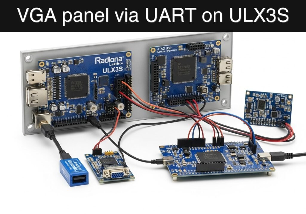
Objective and use case
What you’ll build: A compact UART-driven VGA status panel on the Radiona ULX3S. At 115200 baud, a serial source sends R, Y, or G, and the FPGA updates the full-screen VGA background to red, yellow, or green while matching the state on three LEDs.
Why it matters / Use cases
- Turn a simple 3.3 V UART signal into a large, always-visible local status display without keeping a PC attached.
- Show production, lab, or test-bench state on a monitor with near-instant visual feedback; each command byte arrives in about 87 µs at 115200 baud.
- Teach an end-to-end FPGA pipeline: UART reception, byte decode, registered state storage, VGA timing, and LED/video output.
- Create a reusable debugging module for ULX3S projects where human-readable status is more useful than raw serial logs.
Expected outcome
- A UART receiver running from the ULX3S 25 MHz clock reliably latches one byte at 115200 baud.
- ASCII
Rselects red,Yselects yellow, andGselects green, with invalid bytes ignored. - VGA sync runs continuously while the visible frame updates to the last valid command; at 60 FPS, worst-case screen change is typically visible within one frame.
- A simulation testbench uses a reduced UART divisor and confirms that receiving
Gdrives the green LED/state output.
Audience: FPGA students who know registers and want to combine serial input with video output; Level: Intermediate
Architecture/flow: USB-UART → UART RX @ 25 MHz → command decode/state register → VGA color generation + RGB LEDs
Educational validation note
Before publication, this case passed the Prometeo automated validation gate with status PASS. For this FPGA/ULX3S profile, the synthesizable Verilog blocks were checked with Yosys (read_verilog) and the Verilog design/test set was linted with Verilator. The validator also checked code-block structure, copy/paste-safe ASCII command options, unsupported stacks, and availability of the ULX3S/ECP5 toolchain (yosys, nextpnr-ecp5, ecppack, openFPGALoader).
Published validation evidence
- Automatic result: PASS.
- Parsed structure: 3 sections, 4 tables and 4 code blocks detected before publication.
- Checked code: 2 Verilog/Yosys-Verilator, 1 Bash/copy-paste checks.
- Supported catalog: the article text was checked against Prometeo’s validation-capable device profiles, and unsupported stacks block publication.
- Report findings: no blocking findings.
This validation confirms syntax and tool compatibility for the published code, but it does not replace physical testing on your exact ULX3S board revision, pin-constraint file and real wiring.
Educational safety note
This project is an educational prototype, not a certified product. Before powering the setup, verify the pinout of your exact ULX3S board revision, keep FPGA I/O signals at 3.3 V, never connect 5 V directly to I/O pins, disconnect power before changing wiring, and use suitable external supplies for loads, motors or servos while sharing ground only when the wiring requires it.
Conceptual block diagram
High-level view: what enters the system, what each block processes, and what comes out.
Functional architecture
Conceptual signal and responsibility flow between device blocks.

Validation path
Conceptual summary of the tools used to check the published material.

Prerequisites
- Radiona ULX3S with Lattice ECP5-85F.
- OSS CAD Suite with
verilator,yosys,nextpnr-ecp5,ecppackandopenFPGALoader. - 3.3 V USB-UART adapter connected to the selected
uart_rxpin and common ground. - VGA PMOD or a tested ULX3S VGA wiring adapter.
- Terminal program able to send single characters at 115200 baud.
Materials
| Item | Exact model / signal | Purpose |
|---|---|---|
| FPGA board | Radiona ULX3S, Lattice ECP5-85F | UART decoding and VGA generation |
| Serial adapter | 3.3 V USB-UART, TX connected to FPGA RX | Sends status commands |
| Video output | VGA PMOD or ULX3S VGA wiring | Human-visible dashboard |
| LEDs | Three ULX3S LEDs or PMOD LEDs | Local state mirror |
Setup/Connection
Connect the adapter TX output to the FPGA uart_rx input, connect grounds, and leave the adapter RX disconnected unless you extend the design later. Wire the VGA PMOD according to the LPF pins used in your lab.
| ULX3S signal | Connects to | Notes |
|---|---|---|
clk | 25 MHz board clock | Pixel and UART timing base |
uart_rx | USB-UART TX, 3.3 V | Serial command input |
vga_hsync, vga_vsync | VGA sync pins | 640×480 timing |
vga_r[3:0], vga_g[3:0], vga_b[3:0] | VGA color pins | Simple solid-color status screen |
status_led[2:0] | LEDs | Red/yellow/green mirror |
Validated Code
uart_vga_status_ulx3s.v
Public preview of the validated file. The complete source is shown to members and in PDF/Print.
module uart_vga_status_ulx3s #(
    parameter CLK_HZ = 25000000,
    parameter BAUD = 115200,
    parameter CLKS_PER_BIT = 217
) (
    input wire clk,
    input wire rst_n,
    input wire uart_rx,
    output reg vga_hsync,
    output reg vga_vsync,
    output reg [3:0] vga_r,
    output reg [3:0] vga_g,
    output reg [3:0] vga_b,
    output reg [2:0] status_led
);
    reg [9:0] h_count;
    reg [9:0] v_count;
    reg [1:0] status;
    reg [1:0] rx_state;
    reg [15:0] rx_clk_count;
    reg [2:0] rx_bit_index;
    reg [7:0] rx_shift;
    reg [7:0] rx_byte;
    reg rx_ready;
    reg rx_sync_0;
    reg rx_sync_1;

    localparam RX_IDLE = 2'd0;
    localparam RX_START = 2'd1;
    localparam RX_DATA = 2'd2;
    localparam RX_STOP = 2'd3;

    wire visible = h_count < 10'd640 && v_count < 10'd480;

    always @(posedge clk) begin
        if (!rst_n) begin
            h_count <= 10'd0;
            v_count <= 10'd0;
        end else if (h_count == 10'd799) begin
            h_count <= 10'd0;
            if (v_count == 10'd524) begin
                v_count <= 10'd0;
            end else begin
                v_count <= v_count + 10'd1;
            end
        end else begin
            h_count <= h_count + 10'd1;
        end
    end

    always @(posedge clk) begin
        if (!rst_n) begin
            rx_state <= RX_IDLE;
            rx_clk_count <= 16'd0;
            rx_bit_index <= 3'd0;
            rx_shift <= 8'd0;
            rx_byte <= 8'd0;
            rx_ready <= 1'b0;
            rx_sync_0 <= 1'b1;
            rx_sync_1 <= 1'b1;
        end else begin
            rx_sync_0 <= uart_rx;
            rx_sync_1 <= rx_sync_0;
            rx_ready <= 1'b0;
            case (rx_state)
                RX_IDLE: begin
                    rx_clk_count <= 16'd0;
                    rx_bit_index <= 3'd0;
                    if (!rx_sync_1) begin
                        rx_state <= RX_START;
                    end
                end
// ...module uart_vga_status_ulx3s #(
parameter CLK_HZ = 25000000,
parameter BAUD = 115200,
parameter CLKS_PER_BIT = 217
) (
input wire clk,
input wire rst_n,
input wire uart_rx,
output reg vga_hsync,
output reg vga_vsync,
output reg [3:0] vga_r,
output reg [3:0] vga_g,
output reg [3:0] vga_b,
output reg [2:0] status_led
);
reg [9:0] h_count;
reg [9:0] v_count;
reg [1:0] status;
reg [1:0] rx_state;
reg [15:0] rx_clk_count;
reg [2:0] rx_bit_index;
reg [7:0] rx_shift;
reg [7:0] rx_byte;
reg rx_ready;
reg rx_sync_0;
reg rx_sync_1;
localparam RX_IDLE = 2'd0;
localparam RX_START = 2'd1;
localparam RX_DATA = 2'd2;
localparam RX_STOP = 2'd3;
wire visible = h_count < 10'd640 && v_count < 10'd480;
always @(posedge clk) begin
if (!rst_n) begin
h_count <= 10'd0;
v_count <= 10'd0;
end else if (h_count == 10'd799) begin
h_count <= 10'd0;
if (v_count == 10'd524) begin
v_count <= 10'd0;
end else begin
v_count <= v_count + 10'd1;
end
end else begin
h_count <= h_count + 10'd1;
end
end
always @(posedge clk) begin
if (!rst_n) begin
rx_state <= RX_IDLE;
rx_clk_count <= 16'd0;
rx_bit_index <= 3'd0;
rx_shift <= 8'd0;
rx_byte <= 8'd0;
rx_ready <= 1'b0;
rx_sync_0 <= 1'b1;
rx_sync_1 <= 1'b1;
end else begin
rx_sync_0 <= uart_rx;
rx_sync_1 <= rx_sync_0;
rx_ready <= 1'b0;
case (rx_state)
RX_IDLE: begin
rx_clk_count <= 16'd0;
rx_bit_index <= 3'd0;
if (!rx_sync_1) begin
rx_state <= RX_START;
end
end
                RX_START: begin
                    if (rx_clk_count == (CLKS_PER_BIT / 2)) begin
                        rx_clk_count <= 16'd0;
                        rx_state <= rx_sync_1 ? RX_IDLE : RX_DATA;
                    end else begin
                        rx_clk_count <= rx_clk_count + 16'd1;
                    end
                end
                RX_DATA: begin
                    if (rx_clk_count == CLKS_PER_BIT - 1) begin
                        rx_clk_count <= 16'd0;
                        rx_shift[rx_bit_index] <= rx_sync_1;
                        if (rx_bit_index == 3'd7) begin
                            rx_state <= RX_STOP;
                        end else begin
                            rx_bit_index <= rx_bit_index + 3'd1;
                        end
                    end else begin
                        rx_clk_count <= rx_clk_count + 16'd1;
                    end
                end
                default: begin
                    if (rx_clk_count == CLKS_PER_BIT - 1) begin
                        rx_byte <= rx_shift;
                        rx_ready <= 1'b1;
                        rx_clk_count <= 16'd0;
                        rx_state <= RX_IDLE;
                    end else begin
rx_clk_count <= rx_clk_count + 16'd1;
end
end
endcase
end
end
always @(posedge clk) begin
if (!rst_n) begin
status <= 2'd0;
end else if (rx_ready) begin
if (rx_byte == 8'h52) begin
status <= 2'd0;
end else if (rx_byte == 8'h59) begin
status <= 2'd1;
end else if (rx_byte == 8'h47) begin
status <= 2'd2;
end
end
end
always @* begin
vga_hsync = ~((h_count >= 10'd656) && (h_count < 10'd752));
vga_vsync = ~((v_count >= 10'd490) && (v_count < 10'd492));
status_led = 3'b000;
vga_r = 4'h0;
vga_g = 4'h0;
vga_b = 4'h0;
if (visible) begin
if (status == 2'd0) begin
vga_r = 4'hf;
status_led = 3'b100;
end else if (status == 2'd1) begin
vga_r = 4'hf;
vga_g = 4'hc;
status_led = 3'b110;
end else begin
vga_g = 4'hf;
status_led = 3'b001;
end
end
end
endmodule
tb_uart_vga_status_ulx3s.v
`timescale 1ns/1ps
module tb_uart_vga_status_ulx3s;
    reg clk = 1'b0;
    reg rst_n = 1'b0;
    reg uart_rx = 1'b1;
    wire vga_hsync;
    wire vga_vsync;
    wire [3:0] vga_r;
    wire [3:0] vga_g;
    wire [3:0] vga_b;
    wire [2:0] status_led;

    always #5 clk = ~clk;

    uart_vga_status_ulx3s #(
        .CLKS_PER_BIT(4)
    ) dut (
        .clk(clk),
        .rst_n(rst_n),
        .uart_rx(uart_rx),
        .vga_hsync(vga_hsync),
        .vga_vsync(vga_vsync),
        .vga_r(vga_r),
        .vga_g(vga_g),
        .vga_b(vga_b),
        .status_led(status_led)
    );

    task uart_send;
        input [7:0] value;
        integer i;
    begin
        uart_rx = 1'b0;
        repeat (4) @(posedge clk);
        for (i = 0; i < 8; i = i + 1) begin
            uart_rx = value[i];
            repeat (4) @(posedge clk);
        end
        uart_rx = 1'b1;
        repeat (8) @(posedge clk);
    end
    endtask

    initial begin
        repeat (4) @(posedge clk);
        rst_n = 1'b1;
        uart_send(8'h47);
        repeat (12) @(posedge clk);
        if (status_led != 3'b001) begin
            $fatal(1, "Green status was not latched");
        end
        if (vga_g == 4'h0) begin
            $fatal(1, "VGA green channel is not active");
        end
        $finish;
    end
endmodule
ulx3s_uart_vga_status.lpf
LOCATE COMP "clk" SITE "G2";
IOBUF PORT "clk" IO_TYPE=LVCMOS33;
LOCATE COMP "rst_n" SITE "R1";
IOBUF PORT "rst_n" IO_TYPE=LVCMOS33 PULLMODE=UP;
LOCATE COMP "uart_rx" SITE "P1";
IOBUF PORT "uart_rx" IO_TYPE=LVCMOS33 PULLMODE=UP;
LOCATE COMP "vga_hsync" SITE "A1";
LOCATE COMP "vga_vsync" SITE "B1";
IOBUF PORT "vga_hsync" IO_TYPE=LVCMOS33;
IOBUF PORT "vga_vsync" IO_TYPE=LVCMOS33;
LOCATE COMP "status_led[0]" SITE "C1";
LOCATE COMP "status_led[1]" SITE "D1";
LOCATE COMP "status_led[2]" SITE "E1";
IOBUF PORT "status_led[0]" IO_TYPE=LVCMOS33;
IOBUF PORT "status_led[1]" IO_TYPE=LVCMOS33;
IOBUF PORT "status_led[2]" IO_TYPE=LVCMOS33;
Build/Flash/Run commands
| Step | Command | Expected result |
|---|---|---|
| Lint | verilator --lint-only -Wall -Wno-fatal -Wno-DECLFILENAME --timing uart_vga_status_ulx3s.v tb_uart_vga_status_ulx3s.v | Verilog parses without fatal errors |
| Synthesize | yosys -q -p "read_verilog uart_vga_status_ulx3s.v; synth_ecp5 -top uart_vga_status_ulx3s -json build/uart_vga_status.json" | ECP5 JSON netlist |
| Route | nextpnr-ecp5 --85k --package CABGA381 --speed 6 --json build/uart_vga_status.json --lpf ulx3s_uart_vga_status.lpf --textcfg build/uart_vga_status.config | Routed config |
| Pack | ecppack build/uart_vga_status.config build/uart_vga_status.bit | Bitstream file |
| Program | openFPGALoader -b ulx3s build/uart_vga_status.bit | Board configured |
mkdir -p build
verilator --lint-only -Wall -Wno-fatal -Wno-DECLFILENAME --timing uart_vga_status_ulx3s.v tb_uart_vga_status_ulx3s.v
yosys -q -p "read_verilog uart_vga_status_ulx3s.v; synth_ecp5 -top uart_vga_status_ulx3s -json build/uart_vga_status.json"
nextpnr-ecp5 --85k --package CABGA381 --speed 6 --json build/uart_vga_status.json --lpf ulx3s_uart_vga_status.lpf --textcfg build/uart_vga_status.config
ecppack build/uart_vga_status.config build/uart_vga_status.bit
openFPGALoader -b ulx3s build/uart_vga_status.bit
Step-by-step Validation
- Run the Verilator lint command and confirm that no fatal UART/VGA syntax issue appears.
- Run Yosys and confirm that
build/uart_vga_status.jsonis created from the synthesizable file only. - Route and pack the bitstream with the LPF used in your wiring.
- Program the ULX3S, open a serial terminal at 115200 baud and send
R,YandG. - Confirm that the monitor background and LEDs follow the latest valid byte.
Troubleshooting
| Symptom | Likely cause | Fix |
|---|---|---|
| Screen has sync but wrong color | UART byte is not being received | Check baud rate, ground and adapter TX-to-FPGA RX wiring |
| No VGA image | PMOD pin mapping differs | Update the LPF for your connector |
| Random state changes | UART RX is floating | Keep pull-up enabled and connect a real 3.3 V adapter |
| Upload fails | USB/JTAG not available | Check openFPGALoader -b ulx3s and cable permissions |
Improvements
- Add a small text renderer so the screen shows
RUN,WAITorSTOP. - Add a UART echo transmitter for easier terminal debugging.
- Add a timeout that turns the screen blue if no command arrives for several seconds.
Checklist
- UART adapter is 3.3 V compatible.
- LPF pins match your ULX3S wiring.
- Verilator and Yosys pass before programming.
- VGA sync appears on the monitor.
- Sending
R,YandGchanges the displayed state.
Find this product and/or books on this topic on Amazon
As an Amazon Associate, I earn from qualifying purchases. If you buy through this link, you help keep this project running.
Quick Quiz

Telecommunications Electronics Engineer and Computer Engineer (official degrees in Spain).

