
Objective and use case
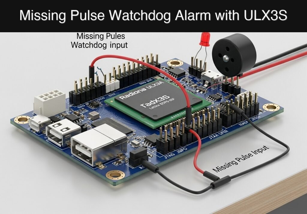
What you’ll build: A hardware-based missing-pulse watchdog alarm that continuously monitors a periodic heartbeat signal. It triggers an audible piezo buzzer and visual LED with deterministic, sub-millisecond latency if the signal drops out within a predefined timeframe.
Why it matters / Use cases
- Embedded System Supervision: Monitors an MCU “heartbeat” square wave, instantly alerting operators if the processor crashes or enters an infinite loop.
- Industrial Automation: Detects stalled conveyor belts or jammed machinery by monitoring optical or magnetic encoder pulses for unexpected stops.
- Security Monitoring: Validates physical line integrity, immediately detecting cut wires or disconnected sensor cables when a continuous pulse goes silent.
Expected outcome
- A synthesized FPGA watchdog timer with cycle-accurate fault detection.
- Immediate GPIO activation of an LED and piezo buzzer upon pulse loss.
- Safety awareness: Understanding that this educational implementation must be replaced by certified, redundant fail-safe hardware in real-world production environments.
Audience: Embedded Systems Engineers, FPGA Developers; Level: Intermediate
Architecture/flow: An incoming signal edge resets an internal FPGA hardware down-counter. If the counter reaches zero (e.g., >50ms elapsed without a pulse), an alarm latch triggers the output GPIOs to drive the buzzer and LED.
Educational validation note
Before publication, this case passed the Prometeo automated validation gate with status PASS. For this FPGA/ULX3S profile, the synthesizable Verilog blocks were checked with Yosys (read_verilog) and the Verilog design/test set was linted with Verilator. The validator also checked code-block structure, copy/paste-safe ASCII command options, unsupported stacks, and availability of the ULX3S/ECP5 toolchain (yosys, nextpnr-ecp5, ecppack, openFPGALoader).
Published validation evidence
- Automatic result: PASS.
- Parsed structure: 3 sections, 1 tables and 4 code blocks detected before publication.
- Checked code: 2 Verilog/Yosys-Verilator, 1 Bash/copy-paste checks.
- Supported catalog: the article text was checked against Prometeo’s validation-capable device profiles, and unsupported stacks block publication.
- Report findings: no blocking findings.
This validation confirms syntax and tool compatibility for the published code, but it does not replace physical testing on your exact ULX3S board revision, pin-constraint file and real wiring.
Educational safety note
This project is an educational prototype, not a certified product. Before powering the setup, verify the pinout of your exact ULX3S board revision, keep FPGA I/O signals at 3.3 V, never connect 5 V directly to I/O pins, disconnect power before changing wiring, and use suitable external supplies for loads, motors or servos while sharing ground only when the wiring requires it.
Prerequisites
To successfully complete this tutorial, you need:
* Basic understanding of digital logic (flip-flops, counters, and clock domains).
* A working installation of the open-source Lattice ECP5 FPGA toolchain:
* Verilator (version 5.0 or newer recommended for --binary support) for linting and simulation.
* Yosys for logic synthesis.
* nextpnr-ecp5 for place and route.
* Project Trellis (ecppack) for bitstream generation.
* openFPGALoader for programming the device.
* A text editor to create Verilog source files, testbenches, and constraint files.
* Basic familiarity with using a command-line interface (CLI) to execute build commands.
Materials
- Radiona ULX3S (Lattice ECP5-85F) FPGA development board.
- Pulse input jumper: A standard male-to-male Dupont jumper wire (used to manually simulate pulses by tapping a 3.3V pin, or to connect an external signal generator).
- Piezo buzzer: A standard passive piezo buzzer module (capable of producing sound when driven by a square wave).
- Status LED: We will use one of the onboard red LEDs provided on the ULX3S board.
- Breadboard and additional jumper wires (optional, for securing the piezo buzzer).
Setup/Connection
The Radiona ULX3S provides versatile GPIO headers (J1 and J2) that operate at 3.3V logic levels. We will use the J1 header for our external connections.
| Component / Function | Physical Connection | FPGA Pin | I/O Standard | Notes |
|---|---|---|---|---|
| System Clock | Onboard 25 MHz Oscillator | G2 | LVCMOS33 | Drives all synchronous logic. |
| Pulse Input | J1 Header, Pin gp[0] | B11 | LVCMOS33 | Internally pulled DOWN. Connect jumper between 3.3V and this pin to simulate a pulse. |
| Piezo Buzzer | J1 Header, Pin gp[1] | A10 | LVCMOS33 | Connect buzzer positive to gp[1], negative to GND on the J1 header. |
| Status LED | Onboard LED 0 | B2 | LVCMOS33 | Illuminates when the watchdog times out. |
Wiring Instructions:
1. Locate the J1 header on the ULX3S.
2. Connect the positive leg of your passive piezo buzzer to the pin labeled gp[1] (FPGA pin A10).
3. Connect the negative leg of the piezo buzzer to a GND pin on the ULX3S.
4. Take your pulse input jumper wire and plug one end into the pin labeled gp[0] (FPGA pin B11). Leave the other end loose for now; you will tap it against a 3.3V pin on the J1 header to simulate incoming heartbeat pulses.
Validated Code
The project consists of three files: the main synthesizable Verilog module, the Verilog testbench for simulation, and the Logical Preference File (LPF) for pin constraints. Save these files in the same working directory.
1. Main Module (watchdog.v)
This module synchronizes the asynchronous input, detects rising edges, counts clock cycles to measure the timeout, and generates a 2 kHz tone if the timeout is reached.
Public preview of the validated file. The complete source is shown to members and in PDF/Print.
/*
 * Module: watchdog
 * Description: Missing-pulse watchdog alarm. Triggers an LED and a 2 kHz
 * piezo buzzer tone if a rising edge is not detected within the timeout period.
 */
module watchdog #(
    // Defaults for 25 MHz clock
    parameter TIMEOUT_CYCLES = 25000000, // 1 second timeout
    parameter TONE_CYCLES    = 12500     // 2 kHz tone period (25M / 2k)
)(
    input  wire clk_25mhz,
    input  wire pulse_in,
    output wire buzzer_out,
    output wire led_out
);

    // --------------------------------------------------------
    // 1. Metastability Synchronizer
    // --------------------------------------------------------
    // The input pulse comes from the outside world and is asynchronous.
    // We use a 2-stage shift register to synchronize it to the 25MHz clock.
    reg [1:0] sync_reg = 2'b00;

    always @(posedge clk_25mhz) begin
        sync_reg <= {sync_reg[0], pulse_in};
    end

    // --------------------------------------------------------
    // 2. Edge Detector
    // --------------------------------------------------------
    // Compare the current synchronized state with the previous state
    // to generate a single-cycle pulse on the rising edge.
    reg pulse_prev = 1'b0;
    wire pulse_edge;

    always @(posedge clk_25mhz) begin
        pulse_prev <= sync_reg[1];
    end

    assign pulse_edge = (sync_reg[1] && !pulse_prev);

    // --------------------------------------------------------
    // 3. Watchdog Timer
    // --------------------------------------------------------
    reg [24:0] timer_cnt = 25'd0;
// .../*
* Module: watchdog
* Description: Missing-pulse watchdog alarm. Triggers an LED and a 2 kHz
* piezo buzzer tone if a rising edge is not detected within the timeout period.
*/
module watchdog #(
// Defaults for 25 MHz clock
parameter TIMEOUT_CYCLES = 25000000, // 1 second timeout
parameter TONE_CYCLES = 12500 // 2 kHz tone period (25M / 2k)
)(
input wire clk_25mhz,
input wire pulse_in,
output wire buzzer_out,
output wire led_out
);
// --------------------------------------------------------
// 1. Metastability Synchronizer
// --------------------------------------------------------
// The input pulse comes from the outside world and is asynchronous.
// We use a 2-stage shift register to synchronize it to the 25MHz clock.
reg [1:0] sync_reg = 2'b00;
always @(posedge clk_25mhz) begin
sync_reg <= {sync_reg[0], pulse_in};
end
// --------------------------------------------------------
// 2. Edge Detector
// --------------------------------------------------------
// Compare the current synchronized state with the previous state
// to generate a single-cycle pulse on the rising edge.
reg pulse_prev = 1'b0;
wire pulse_edge;
always @(posedge clk_25mhz) begin
pulse_prev <= sync_reg[1];
end
assign pulse_edge = (sync_reg[1] && !pulse_prev);
// --------------------------------------------------------
// 3. Watchdog Timer
// --------------------------------------------------------
reg [24:0] timer_cnt = 25'd0;
    reg alarm_state = 1'b0;

    always @(posedge clk_25mhz) begin
        if (pulse_edge) begin
            // Valid pulse received: reset timer and clear alarm
            timer_cnt <= 25'd0;
            alarm_state <= 1'b0;
        end else if (timer_cnt < TIMEOUT_CYCLES) begin
            // No pulse, but timeout not yet reached: increment timer
            timer_cnt <= timer_cnt + 1'b1;
        end else begin
            // Timeout reached: trigger alarm
            alarm_state <= 1'b1;
        end
    end

    // --------------------------------------------------------
    // 4. Tone Generator (2 kHz Square Wave)
    // --------------------------------------------------------
    reg [13:0] tone_cnt = 14'd0;
    reg tone_out = 1'b0;

    always @(posedge clk_25mhz) begin
        if (alarm_state) begin
            // Toggle the buzzer state every half-period
            if (tone_cnt >= (TONE_CYCLES / 2) - 1) begin
                tone_cnt <= 14'd0;
                tone_out <= ~tone_out;
end else begin
tone_cnt <= tone_cnt + 1'b1;
end
end else begin
// Ensure buzzer is silent when alarm is inactive
tone_cnt <= 14'd0;
tone_out <= 1'b0;
end
end
// --------------------------------------------------------
// 5. Output Assignments
// --------------------------------------------------------
assign buzzer_out = tone_out;
assign led_out = alarm_state;
endmodule
2. Testbench (watchdog_tb.v)
The testbench overrides the default timing parameters to speed up simulation. Simulating 25 million cycles would be computationally expensive and unnecessary for verifying logic. The testbench automatically checks if the output properly asserts and resets.
Public preview of the validated file. The complete source is shown to members and in PDF/Print.
/*
 * Module: watchdog_tb
 * Description: Simulation testbench for the missing-pulse watchdog.
 */
`timescale 1ns/1ps

module watchdog_tb;

    reg clk;
    reg pulse_in;
    wire buzzer_out;
    wire led_out;

    // Instantiate the Device Under Test (DUT)
    // Override parameters for faster simulation:
    // Timeout = 100 cycles, Tone period = 10 cycles
    watchdog #(
        .TIMEOUT_CYCLES(100),
        .TONE_CYCLES(10)
    ) dut (
        .clk_25mhz(clk),
        .pulse_in(pulse_in),
        .buzzer_out(buzzer_out),
        .led_out(led_out)
    );

    // Clock generation (25 MHz = 40ns period)
    initial clk = 0;
    always #20 clk = ~clk;

    initial begin
        $dumpfile("watchdog_tb.vcd");
        $dumpvars(0, watchdog_tb);

        // Initialize inputs
        pulse_in = 0;
// .../*
* Module: watchdog_tb
* Description: Simulation testbench for the missing-pulse watchdog.
*/
`timescale 1ns/1ps
module watchdog_tb;
reg clk;
reg pulse_in;
wire buzzer_out;
wire led_out;
// Instantiate the Device Under Test (DUT)
// Override parameters for faster simulation:
// Timeout = 100 cycles, Tone period = 10 cycles
watchdog #(
.TIMEOUT_CYCLES(100),
.TONE_CYCLES(10)
) dut (
.clk_25mhz(clk),
.pulse_in(pulse_in),
.buzzer_out(buzzer_out),
.led_out(led_out)
);
// Clock generation (25 MHz = 40ns period)
initial clk = 0;
always #20 clk = ~clk;
initial begin
$dumpfile("watchdog_tb.vcd");
$dumpvars(0, watchdog_tb);
// Initialize inputs
pulse_in = 0;
        // Wait for reset/initialization
        #100;

        // Apply a pulse
        pulse_in = 1;
        #40;
        pulse_in = 0;

        // Wait for timeout (100 cycles * 40ns = 4000ns)
        #5000;

        if (led_out !== 1'b1) begin
            $display("FAIL: Alarm did not trigger after timeout.");
        end else begin
            $display("PASS: Alarm triggered successfully.");
        end

        // Apply another pulse to reset alarm
        pulse_in = 1;
        #40;
        pulse_in = 0;

        #100;
        if (led_out !== 1'b0) begin
            $display("FAIL: Alarm did not clear after new pulse.");
        end else begin
            $display("PASS: Alarm cleared successfully.");
end
#1000;
$finish;
end
endmodule
3. Constraints File (ulx3s.lpf)
This file maps the top-level Verilog ports to the physical pins on the Radiona ULX3S ECP5-85F board.
LOCATE COMP "clk_25mhz" SITE "G2";
IOBUF COMP "clk_25mhz" IO_TYPE=LVCMOS33;

LOCATE COMP "pulse_in" SITE "B11";
IOBUF COMP "pulse_in" IO_TYPE=LVCMOS33 PULLMODE=DOWN;

LOCATE COMP "buzzer_out" SITE "A10";
IOBUF COMP "buzzer_out" IO_TYPE=LVCMOS33;

LOCATE COMP "led_out" SITE "B2";
IOBUF COMP "led_out" IO_TYPE=LVCMOS33;
Build and Validation
Execute the following commands in your terminal to simulate the logic, synthesize the design, and program the ULX3S FPGA board.
# 1. Lint and simulate with Verilator to validate logic
verilator --binary --trace watchdog.v watchdog_tb.v
./obj_dir/Vwatchdog_tb

# 2. Synthesize with Yosys
yosys -p "synth_ecp5 -top watchdog -json watchdog.json" watchdog.v

# 3. Place and Route with nextpnr
nextpnr-ecp5 --85k --package CABGA381 --json watchdog.json --lpf ulx3s.lpf --textcfg watchdog.config

# 4. Pack bitstream
ecppack watchdog.config watchdog.bit

# 5. Program the ULX3S via openFPGALoader
openFPGALoader --board ulx3s watchdog.bit
Expected Validation Evidence:
1. Simulation Phase: The Verilator execution (./obj_dir/Vwatchdog_tb) should print PASS: Alarm triggered successfully. followed by PASS: Alarm cleared successfully. to the console, confirming accurate cycle counting.
2. Hardware Phase: Upon flashing, the red LED will immediately turn on and the buzzer will sound a 2 kHz tone because no pulses are arriving.
3. Manual Test: Tap the loose jumper wire against the 3.3V pin on the J1 header. The LED and buzzer will instantly turn off. If you stop tapping, exactly 1.0 seconds later, the alarm will resume.
Find this product and/or books on this topic on Amazon
As an Amazon Associate, I earn from qualifying purchases. If you buy through this link, you help keep this project running.
Quick Quiz

Telecommunications Electronics Engineer and Computer Engineer (official degrees in Spain).

