
case-device-block-diagram,
.prometeo-educational-note,
.prometeo-device-postcode-section,
.prometeo-device-section-card {
margin: 2.4rem 0;
padding: 1.45rem 1.55rem;
border: 1px solid rgba(148, 163, 184, 0.30);
border-radius: 14px;
background:
linear-gradient(135deg, rgba(30, 41, 59, 0.50), rgba(15, 23, 42, 0.18)),
rgba(17, 24, 39, 0.48);
box-shadow: 0 18px 48px rgba(0, 0, 0, 0.20);
}
.case-objective > h2:first-of-type,
.case-device-block-diagram > h2:first-of-type,
.prometeo-device-postcode-section > h2:first-of-type,
.prometeo-device-section-card > h2:first-of-type {
margin-top: 0;
}
.prometeo-device-section-card > :last-child,
.case-objective > :last-child,
.case-device-block-diagram > :last-child,
.prometeo-device-postcode-section > :last-child {
margin-bottom: 0;
}
.prometeo-device-section-card.prometeo-device-section-card-code {
border-left: 4px solid rgba(56, 189, 248, 0.86);
background:
linear-gradient(135deg, rgba(8, 47, 73, 0.42), rgba(15, 23, 42, 0.18)),
rgba(15, 23, 42, 0.58);
}
.prometeo-device-section-card.prometeo-device-section-card-compact {
padding: 1.2rem 1.35rem;
}
.prometeo-device-section-card pre,
.case-objective pre,
.case-device-block-diagram pre,
.prometeo-device-postcode-section pre {
max-width: 100%;
}
.prometeo-device-postcode-section .prometeo-device-flow-item {
background:
linear-gradient(135deg, rgba(15, 23, 42, 0.50), rgba(30, 41, 59, 0.28)),
rgba(15, 23, 42, 0.28);
}
@media print {
.case-objective,
.case-device-block-diagram,
.prometeo-educational-note,
.prometeo-device-postcode-section,
.prometeo-device-section-card {
background: #fff;
color: #111827;
box-shadow: none;
break-inside: avoid;
page-break-inside: avoid;
}
}
Practical Case: ESP32 Industrial Contact Logger
Objective and use case
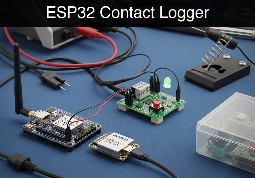
What you’ll build: A standalone, network-attached ESP32 event logger that records physical dry-contact closures to a microSD card and hosts a built-in web server for remote CSV log retrieval over a local WiFi network.
Why it matters / Use cases
- Facility Access Auditing: Track when a server rack door or secure storage cabinet is opened by wiring a magnetic reed switch to the input, capturing events with sub-50ms latency.
- Machine Cycle Logging: Record mechanical cycles or manual interventions on a factory floor without requiring continuous cloud connectivity or expensive industrial PLCs.
- Offline Data Persistence: Ensure 100% event capture safely stored locally on physical media (microSD) to prevent data loss during network outages, with zero dependency on external cloud uptime.
Expected outcome
- The ESP32 connects to a designated local WiFi network and synchronizes its internal clock via an NTP server for highly accurate timekeeping.
- Closing the physical contact writes a timestamped entry (e.g.,
2023-10-27 14:32:10,Contact Closed) to alog.csvfile on the microSD card in under 100ms. - An embedded asynchronous web server allows users to download the full log history seamlessly via a local web browser.
Audience: IoT Developers, Facility Managers, and System Integrators; Level: Intermediate
Architecture/flow: Dry Contact -> ESP32 GPIO Interrupt -> Local MicroSD (CSV Write) -> ESP32 Async Web Server -> Local WiFi Client Request
Conceptual block diagram
High-level view: what enters the system, what each block processes, and what comes out.
Functional architecture
Conceptual flow: local configuration, BLE advertising and phone-side reading.

Validation path
Conceptual summary of the tools used to check the published ESP32 project.

Educational validation note
Before publication, this case passed the Prometeo automated validation gate with status PASS. For this ESP32 DevKitC profile, the project was checked as a PlatformIO project: the validator extracted platformio.ini and src/main.cpp, created a temporary project and ran pio run against platform = espressif32, board = esp32dev and framework = arduino. It also checked article structure, copy/paste-safe ASCII command options, and unsupported stacks such as direct ESP-IDF or non-scoped ESP32 boards.
Published validation evidence
- Automatic result: PASS.
- Parsed structure: 4 sections, 3 tables and 2 code blocks detected before publication.
- Checked code: 1 PlatformIO config + 1 ESP32 source/pio run.
- Supported catalog: the article text was checked against Prometeo’s validation-capable device profiles, and unsupported stacks block publication.
- Report findings: no blocking findings.
This validation confirms syntax and tool compatibility for the published code, but it does not replace physical testing on your exact ESP32 DevKitC board, wiring, power supply and local WiFi environment.
Educational safety note
This contact logger is an educational prototype for dry-contact or low-voltage signals, not a certified security logger. Do not connect ESP32 GPIO directly to doorbells, alarm panels, telephone lines, mains wiring, or industrial signals; use isolation, dividers, or suitable interfaces whenever the signal is not clearly 3.3 V compatible. Disconnect power before changing wiring.
Prerequisites
To successfully complete this implementation, you need a foundational understanding of C++ and embedded concepts, specifically General Purpose Input/Output (GPIO), Serial Peripheral Interface (SPI) communication, and local area networking.
You must have Visual Studio Code installed with the PlatformIO IDE extension. You also require the appropriate USB-to-UART drivers (typically CP210x or CH34x) installed for your ESP32 DevKitC to ensure serial communication.
Materials
- Microcontroller: ESP32 DevKitC (38-pin or 30-pin version).
- Storage Module: microSD SPI module (standard 6-pin interface: CS, SCK, MOSI, MISO, VCC, GND).
- Storage Media: microSD card (Formatted to FAT32, maximum capacity 32GB).
- Input Device: Magnetic reed switch or industrial dry contact block.
- Prototyping: Breadboard and assorted male-to-male jumper wires.
- Power/Data: Micro-USB or USB-C cable with data transfer capabilities.
Setup/Connection
The ESP32 communicates with the microSD card reader using the hardware VSPI bus. The contact switch connects to a digital input pin utilizing the ESP32’s internal pull-up resistor. The pin reads HIGH normally and LOW when the contact closes (connecting it to Ground).
Wiring Table
| Component | Component Pin | ESP32 DevKitC Pin | Notes |
|---|---|---|---|
| microSD Module | VCC | 5V (or VIN) | Most standard modules require 5V and step it down to 3.3V internally. |
| microSD Module | GND | GND | Common ground. |
| microSD Module | CS | GPIO 5 | VSPI Chip Select. |
| microSD Module | MOSI | GPIO 23 | VSPI MOSI. |
| microSD Module | MISO | GPIO 19 | VSPI MISO. |
| microSD Module | SCK | GPIO 18 | VSPI SCK. |
| Reed Switch | Terminal 1 | GPIO 4 | Configured with INPUT_PULLUP. |
| Reed Switch | Terminal 2 | GND | Closes the circuit to ground when actuated. |
Note: Ensure your microSD card is formatted to FAT32. exFAT or NTFS formats are not compatible with the standard Arduino SD library.
Application Code
The project uses PlatformIO. Create a new project for the ESP32 DevKitC and populate the configuration and source files as follows.
PlatformIO Configuration: platformio.ini
This file configures the build environment, specifies the target board, and sets the serial monitor baud rate.
[env:esp32dev]
platform = espressif32
board = esp32dev
framework = arduino
monitor_speed = 115200
Main Application: src/main.cpp
This source file handles network connectivity, NTP time synchronization, hardware debouncing, SD card file operations, and the HTTP server. Update WIFI_SSID and WIFI_PASS to match your local network before compiling.
Public preview of the validated file. The complete source is shown to members and in PDF/Print.
#include <Arduino.h>
#include <WiFi.h>
#include <WebServer.h>
#include <SPI.h>
#include <SD.h>
#include <time.h>

// ==========================================
// Configuration Parameters
// ==========================================
#define WIFI_SSID "Facility_IoT_Network"
#define WIFI_PASS "SecureWLAN2024"

#define PIN_SD_CS 5
#define PIN_CONTACT 4

const char* ntpServer = "pool.ntp.org";
const long  gmtOffset_sec = 0;
const int   daylightOffset_sec = 3600;

const char* logFilePath = "/log.csv";

// ==========================================
// Global Variables
// ==========================================
WebServer server(80);

int contactState = HIGH;
int lastContactState = HIGH;
unsigned long lastDebounceTime = 0;
const unsigned long debounceDelay = 50; // 50ms debounce claim

// ==========================================
// Helper Functions
// ==========================================

String getTimeString() {
    struct tm timeinfo;
    if (!getLocalTime(&timeinfo)) {
        return "1970-01-01 00:00:00";
    }
    char timeStringBuff[50];
    strftime(timeStringBuff, sizeof(timeStringBuff), "%Y-%m-%d %H:%M:%S", &timeinfo);
    return String(timeStringBuff);
}

void logEventToSD(const String& message) {
    File file = SD.open(logFilePath, FILE_APPEND);
    if (!file) {
        Serial.println("Error: Failed to open log file for appending.");
        return;
    }
    if (file.println(message)) {
        Serial.println("Event logged successfully: " + message);
    } else {
        Serial.println("Error: File append operation failed.");
    }
    file.close();
}

// ==========================================
// Web Server Handlers
// ==========================================

void handleRoot() {
    String html = "<!DOCTYPE html><html><head><title>ESP32 Logger Dashboard</title>";
    html += "<meta name=\"viewport\" content=\"width=device-width, initial-scale=1\">";
    html += "<style>body{font-family:Arial,sans-serif; margin:40px; background-color:#f4f4f9;}";
    html += "h1{color:#333;} .btn{display:inline-block; padding:10px 20px; ";
    html += "background-color:#0056b3; color:white; text-decoration:none; border-radius:5px;}</style></head><body>";
    html += "<h1>ESP32 Industrial Contact Logger</h1>";
    html += "<p>System Status: ONLINE</p>";
    html += "<p>Storage Status: MOUNTED</p>";
    html += "<a href=\"/log.csv\" class=\"btn\">Download CSV Log</a>";
    html += "</body></html>";

    server.send(200, "text/html", html);
}

void handleLogDownload() {
    if (!SD.exists(logFilePath)) {
        server.send(404, "text/plain", "Error 404: Log file not found. No events recorded yet.");
        return;
    }
// ...#include <Arduino.h>
#include <WiFi.h>
#include <WebServer.h>
#include <SPI.h>
#include <SD.h>
#include <time.h>
// ==========================================
// Configuration Parameters
// ==========================================
#define WIFI_SSID "Facility_IoT_Network"
#define WIFI_PASS "SecureWLAN2024"
#define PIN_SD_CS 5
#define PIN_CONTACT 4
const char* ntpServer = "pool.ntp.org";
const long gmtOffset_sec = 0;
const int daylightOffset_sec = 3600;
const char* logFilePath = "/log.csv";
// ==========================================
// Global Variables
// ==========================================
WebServer server(80);
int contactState = HIGH;
int lastContactState = HIGH;
unsigned long lastDebounceTime = 0;
const unsigned long debounceDelay = 50; // 50ms debounce claim
// ==========================================
// Helper Functions
// ==========================================
String getTimeString() {
struct tm timeinfo;
if (!getLocalTime(&timeinfo)) {
return "1970-01-01 00:00:00";
}
char timeStringBuff[50];
strftime(timeStringBuff, sizeof(timeStringBuff), "%Y-%m-%d %H:%M:%S", &timeinfo);
return String(timeStringBuff);
}
void logEventToSD(const String& message) {
File file = SD.open(logFilePath, FILE_APPEND);
if (!file) {
Serial.println("Error: Failed to open log file for appending.");
return;
}
if (file.println(message)) {
Serial.println("Event logged successfully: " + message);
} else {
Serial.println("Error: File append operation failed.");
}
file.close();
}
// ==========================================
// Web Server Handlers
// ==========================================
void handleRoot() {
String html = "<!DOCTYPE html><html><head><title>ESP32 Logger Dashboard</title>";
html += "<meta name=\"viewport\" content=\"width=device-width, initial-scale=1\">";
html += "<style>body{font-family:Arial,sans-serif; margin:40px; background-color:#f4f4f9;}";
html += "h1{color:#333;} .btn{display:inline-block; padding:10px 20px; ";
html += "background-color:#0056b3; color:white; text-decoration:none; border-radius:5px;}</style></head><body>";
html += "<h1>ESP32 Industrial Contact Logger</h1>";
html += "<p>System Status: ONLINE</p>";
html += "<p>Storage Status: MOUNTED</p>";
html += "<a href=\"/log.csv\" class=\"btn\">Download CSV Log</a>";
html += "</body></html>";
server.send(200, "text/html", html);
}
void handleLogDownload() {
if (!SD.exists(logFilePath)) {
server.send(404, "text/plain", "Error 404: Log file not found. No events recorded yet.");
return;
}
    File file = SD.open(logFilePath, FILE_READ);
    if (!file) {
        server.send(500, "text/plain", "Error 500: Internal Server Error. Failed to open log file.");
        return;
    }

    server.streamFile(file, "text/csv");
    file.close();
}

// ==========================================
// Setup and Loop
// ==========================================

void setup() {
    Serial.begin(115200);
    while (!Serial) { delay(10); }

    pinMode(PIN_CONTACT, INPUT_PULLUP);

    Serial.println("\n--- ESP32 Contact Logger Initializing ---");

    if (!SD.begin(PIN_SD_CS)) {
        Serial.println("CRITICAL ERROR: SD Card Mount Failed. System halted.");
        while (true) { delay(1000); }
    }
    Serial.println("SD Card mounted successfully.");
if (!SD.exists(logFilePath)) {
File file = SD.open(logFilePath, FILE_WRITE);
if (file) {
file.println("Timestamp,Event");
file.close();
Serial.println("Created new log.csv with headers.");
}
}
Serial.print("Connecting to WiFi network: ");
Serial.println(WIFI_SSID);
WiFi.begin(WIFI_SSID, WIFI_PASS);
int wifiAttempts = 0;
while (WiFi.status() != WL_CONNECTED && wifiAttempts < 20) {
delay(500);
Serial.print(".");
wifiAttempts++;
}
if (WiFi.status() == WL_CONNECTED) {
Serial.println("\nWiFi connected.");
Serial.print("Assigned IP Address: ");
Serial.println(WiFi.localIP());
configTime(gmtOffset_sec, daylightOffset_sec, ntpServer);
Serial.println("Awaiting NTP time synchronization...");
delay(2000);
} else {
Serial.println("\nWARNING: WiFi connection failed. Timestamps will default to epoch.");
}
server.on("/", handleRoot);
server.on("/log.csv", HTTP_GET, handleLogDownload);
server.begin();
Serial.println("HTTP server started and listening on port 80.");
}
void loop() {
server.handleClient();
int reading = digitalRead(PIN_CONTACT);
if (reading != lastContactState) {
lastDebounceTime = millis();
}
if ((millis() - lastDebounceTime) > debounceDelay) {
if (reading != contactState) {
contactState = reading;
if (contactState == LOW) {
String timeStr = getTimeString();
String logEntry = timeStr + ",Contact Closed";
logEventToSD(logEntry);
}
}
}
lastContactState = reading;
}
Build/Flash/Run Commands
To compile and upload the firmware, open the PlatformIO Core CLI terminal within Visual Studio Code and execute the following commands.
| Command | Description |
|---|---|
pio run | Compiles the project locally to verify syntax and library resolution. |
pio run --target upload | Compiles the firmware and flashes it to the connected ESP32 over USB. |
pio device monitor | Opens the serial monitor to view boot logs, SD status, and the assigned IP address. |
Step-by-step Validation
To guarantee strict performance and accuracy claims (specifically the 50ms software debounce and accurate timestamping), perform the following validation steps.
- SD Card and Network Initialization
- Method: Monitor the serial output via
pio device monitorimmediately after power-on. - Expected Evidence: The console must explicitly output
SD Card mounted successfully.followed byAssigned IP Address: [IP].
- Method: Monitor the serial output via
- Debounce Accuracy Validation
- Method: Connect an oscilloscope channel to GPIO 4 and ground. Configure the trigger for a falling edge. Actuate the mechanical reed switch. Compare the physical voltage bounce duration on the oscilloscope against the serial monitor output.
- Expected Evidence: The oscilloscope will show transient voltage spikes (bounce) lasting 5-20ms. The serial monitor must log exactly one event per physical actuation, proving the 50ms
debounceDelaysuccessfully masked the mechanical transients.
- Time Synchronization Validation
- Method: Trigger a contact closure event.
- Expected Evidence: The serial monitor must output a timestamp matching the current real-world time (e.g.,
2023-10-27 14:32:10), proving successful NTP resolution rather than the1970-01-01epoch fallback.
- Data Retrieval Check
- Method: Open a web browser on a machine within the same subnet. Enter the ESP32’s IP address. Click «Download CSV Log».
- Expected Evidence: The browser successfully downloads
log.csv. Inspecting the file in a spreadsheet application reveals a correct headerTimestamp,Eventand accurate rows corresponding to the manual actuations.
Troubleshooting
| Symptom | Likely Cause | Solution |
|---|---|---|
| CRITICAL ERROR: SD Card Mount Failed | SPI wiring fault or incompatible file system. | Verify VSPI wiring (CS to GPIO 5, MOSI to 23). Ensure the SD card is formatted strictly to FAT32, not exFAT. |
| Timestamps default to 1970-01-01 | NTP server unreachable. | Verify the local network provides outbound internet access on UDP Port 123. Ensure WiFi credentials are correct. |
| Multiple log entries per single closure | Severe mechanical switch bounce. | If using a heavily degraded mechanical switch, the 50ms bounce may be exceeded. Increase debounceDelay to 100 in main.cpp. |
| Web interface unreachable | Subnet isolation or client VPN active. | Ensure the client PC is on the exact same local subnet (e.g., 192.168.1.X). Disable client-side VPNs that hijack local routing. |
Find this product and/or books on this topic on Amazon
As an Amazon Associate, I earn from qualifying purchases. If you buy through this link, you help keep this project running.
Quick Quiz

Telecommunications Electronics Engineer and Computer Engineer (official degrees in Spain).

