Level: Basic – Implement an OR gate to activate an alert from two independent switches.
Objective and use case
You will build a basic nurse call circuit using a digital OR gate to trigger a visual alert whenever either of two patient bed switches is pressed.
Why it is useful:
* Allows centralized monitoring of multiple independent trigger points.
* Demonstrates how basic digital logic simplifies parallel alarm systems without cross-wiring physical switches.
* Forms the foundation for larger, more complex call bell or security systems.
Expected outcome:
* Pressing switch A drives the output HIGH (near 5 V), lighting the LED.
* Pressing switch B drives the output HIGH (near 5 V), lighting the LED.
* Pressing both switches simultaneously drives the output HIGH, lighting the LED.
* The output remains LOW (0 V) and the LED stays off when no switches are pressed.
Target audience and level: Beginners learning digital logic gates and the importance of pull-down networks.
Materials
- V1: 5 V DC supply
- U1: 74HC32 quad 2-input OR gate IC
- SW1: Push button switch, normally open, function: Bed A trigger
- SW2: Push button switch, normally open, function: Bed B trigger
- R1: 10 kΩ resistor, function: pull-down for VA
- R2: 10 kΩ resistor, function: pull-down for VB
- R3: 330 Ω resistor, function: LED current limiting
- D1: Red LED, function: alert indicator
Pin-out of the IC used
74HC32 (Quad 2-Input OR Gate)
| Pin | Name | Logic function | Connection in this case |
|---|---|---|---|
| 1 | 1 A | Input 1 for Gate 1 | Node VA (Switch A) |
| 2 | 1B | Input 2 for Gate 1 | Node VB (Switch B) |
| 3 | 1Y | Output of Gate 1 | Node VOUT (to LED circuit) |
| 7 | GND | Ground | Node 0 |
| 14 | VCC | Power Supply | Node VCC |
(Note: Pins 4, 5, 8, 9, 10, 11, 12, 13 are unused inputs and should be tied to Ground in a permanent circuit to prevent CMOS latch-up).
Wiring guide
- V1: positive terminal connects to VCC; negative terminal connects to 0.
- SW1: connects between VCC and VA.
- SW2: connects between VCC and VB.
- R1: connects between VA and 0.
- R2: connects between VB and 0.
- U1 (pin 14): connects to VCC.
- U1 (pin 7): connects to 0.
- U1 (pin 1): connects to VA.
- U1 (pin 2): connects to VB.
- U1 (pin 3): connects to VOUT.
- R3: connects between VOUT and the anode of D1.
- D1: cathode connects to 0.
Conceptual block diagram
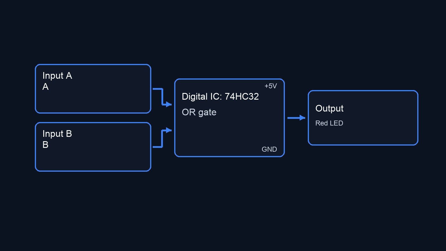
Schematic
VCC --> [ SW1: Bed A ] --(VA)--> [ R1: 10 kΩ Pull-down ] --> GND
                             \
                              -->(Pin 1) \
                                          [ U1: 74HC32 OR Gate ] --(VOUT, Pin 3)--> [ R3: 330 Ω ] --> [ D1: Red LED ] --> GND
                                          /
                              -->(Pin 2) /
                             /
VCC --> [ SW2: Bed B ] --(VB)--> [ R2: 10 kΩ Pull-down ] --> GND
Truth table
Input A (VA) | Input B (VB) | Output Y (VOUT) | LED State |
|---|---|---|---|
| 0 (LOW) | 0 (LOW) | 0 (LOW) | OFF |
| 0 (LOW) | 1 (HIGH) | 1 (HIGH) | ON |
| 1 (HIGH) | 0 (LOW) | 1 (HIGH) | ON |
| 1 (HIGH) | 1 (HIGH) | 1 (HIGH) | ON |
Measurements and tests
- Power Verification: Measure the voltage between VCC and 0 using a multimeter to ensure it is exactly 5 V.
- Idle State Testing: Without pressing any buttons, measure the voltage at nodes VA and VB. Both should read exactly 0 V. The node VOUT should also read 0 V.
- Logic HIGH Testing: Press and hold SW1. Measure node VA (should be ~5 V) and measure node VOUT (should be ~5 V). Verify the LED is ON. Repeat this process for SW2 and node VB.
- Current Measurement (Optional): Place your multimeter in series with R3 and D1 to measure the forward current of the LED (it should be roughly 8-10 mA depending on the LED’s forward voltage drop).
SPICE netlist and simulation
Reference SPICE Netlist (ngspice) — excerptFull SPICE netlist (ngspice)
* Practical case: Nurse call bell
.width out=256

* Power Supply
V1 VCC 0 DC 5

* Bed A Trigger (SW1)
* Modeled as a voltage-controlled switch activated by a pulse to simulate a user pressing the button
VctrlA ctrlA 0 PULSE(0 5 10u 1u 1u 40u 100u)
S1 VCC VA ctrlA 0 my_switch

* Bed B Trigger (SW2)
* Modeled as a voltage-controlled switch activated by a pulse to simulate a user pressing the button
VctrlB ctrlB 0 PULSE(0 5 10u 1u 1u 90u 200u)
S2 VCC VB ctrlB 0 my_switch

* Pull-down resistors for switch inputs
R1 VA 0 10k
R2 VB 0 10k

* ... (truncated in public view) ...
Copy this content into a .cir file and run with ngspice.
* Practical case: Nurse call bell
.width out=256

* Power Supply
V1 VCC 0 DC 5

* Bed A Trigger (SW1)
* Modeled as a voltage-controlled switch activated by a pulse to simulate a user pressing the button
VctrlA ctrlA 0 PULSE(0 5 10u 1u 1u 40u 100u)
S1 VCC VA ctrlA 0 my_switch

* Bed B Trigger (SW2)
* Modeled as a voltage-controlled switch activated by a pulse to simulate a user pressing the button
VctrlB ctrlB 0 PULSE(0 5 10u 1u 1u 90u 200u)
S2 VCC VB ctrlB 0 my_switch

* Pull-down resistors for switch inputs
R1 VA 0 10k
R2 VB 0 10k

* U1: 74HC32 quad 2-input OR gate IC (using 1 gate)
* Wiring: Pin 1 -> VA, Pin 2 -> VB, Pin 3 -> VOUT, Pin 14 -> VCC, Pin 7 -> 0
XU1 VA VB VOUT VCC 0 74HC32_OR

* Alert Indicator (LED and current limiting resistor)
R3 VOUT D1_A 330
D1 D1_A 0 DLED

* --- Models and Subcircuits ---

* Ideal switch model
.model my_switch SW(vt=2.5 vh=0.5 ron=1 roff=100MEG)

* Generic Red LED model
.model DLED D(IS=1e-20 N=2.2 RS=2)

* Behavioral model for a 74HC32 OR gate (Continuous functions for robust convergence)
.subckt 74HC32_OR A B Y VCC GND
RinA A GND 10MEG
RinB B GND 10MEG
* OR Logic: V_out = VCC * (1 - (1-A)*(1-B)) implemented with sigmoids
B1 Y_int GND V = V(VCC) * (1 - (1 - 1/(1+exp(-50*(V(A)-2.5)))) * (1 - 1/(1+exp(-50*(V(B)-2.5)))))
Rout Y_int Y 10
.ends

* --- Analysis Directives ---

.tran 1u 250u
.print tran V(VA) V(VB) V(VOUT) V(D1_A)
.op
.end
Simulation Results (Transient Analysis)

Show raw data table (354 rows)
Index   time            v(va)           v(vb)           v(vout)         v(d1_a)
0	0.000000e+00	4.994506e-04	4.994506e-04	-1.00582e-35	-3.41977e-34
1	1.000000e-08	4.994506e-04	4.994506e-04	-6.04520e-52	-2.05537e-50
2	2.000000e-08	4.994506e-04	4.994506e-04	6.045198e-52	2.055367e-50
3	4.000000e-08	4.994506e-04	4.994506e-04	1.816637e-67	6.176631e-66
4	8.000000e-08	4.994506e-04	4.994506e-04	-7.26682e-68	-2.47066e-66
5	1.600000e-07	4.994506e-04	4.994506e-04	-1.94609e-72	-1.94609e-72
6	3.200000e-07	4.994506e-04	4.994506e-04	-1.94609e-72	-1.94609e-72
7	6.400000e-07	4.994506e-04	4.994506e-04	-1.94609e-72	-1.94609e-72
8	1.280000e-06	4.994506e-04	4.994506e-04	-1.94609e-72	-1.94609e-72
9	2.280000e-06	4.994506e-04	4.994506e-04	-1.94609e-72	-1.94609e-72
10	3.280000e-06	4.994506e-04	4.994506e-04	-1.94609e-72	-1.94609e-72
11	4.280000e-06	4.994506e-04	4.994506e-04	-1.94609e-72	-1.94609e-72
12	5.280000e-06	4.994506e-04	4.994506e-04	-1.94609e-72	-1.94609e-72
13	6.280000e-06	4.994506e-04	4.994506e-04	-1.94609e-72	-1.94609e-72
14	7.280000e-06	4.994506e-04	4.994506e-04	-1.94609e-72	-1.94609e-72
15	8.280000e-06	4.994506e-04	4.994506e-04	-1.94609e-72	-1.94609e-72
16	9.280000e-06	4.994506e-04	4.994506e-04	-1.94609e-72	-1.94609e-72
17	1.000000e-05	4.994506e-04	4.994506e-04	-1.94609e-72	-1.94609e-72
18	1.010000e-05	4.994506e-04	4.994506e-04	-1.94609e-72	-1.94609e-72
19	1.030000e-05	4.994506e-04	4.994506e-04	-1.94609e-72	-1.94609e-72
20	1.035875e-05	4.994506e-04	4.994506e-04	-1.94609e-72	-1.94609e-72
21	1.046156e-05	4.994506e-04	4.994506e-04	-1.94609e-72	-1.94609e-72
22	1.049002e-05	4.994506e-04	4.994506e-04	-1.94609e-72	-1.94609e-72
23	1.053982e-05	4.994506e-04	4.994506e-04	-1.94609e-72	-1.94609e-72
... (330 more rows) ...
Reference SPICE netlist (ngspice)
* Practical case: Nurse call bell
.width out=256

* Power Supply
V1 VCC 0 DC 5

* Bed A Trigger (SW1)
* Modeled as a voltage-controlled switch activated by a pulse to simulate a user pressing the button
VctrlA ctrlA 0 PULSE(0 5 10u 1u 1u 40u 100u)
S1 VCC VA ctrlA 0 my_switch

* Bed B Trigger (SW2)
* Modeled as a voltage-controlled switch activated by a pulse to simulate a user pressing the button
VctrlB ctrlB 0 PULSE(0 5 10u 1u 1u 90u 200u)
S2 VCC VB ctrlB 0 my_switch

* Pull-down resistors for switch inputs
R1 VA 0 10k
R2 VB 0 10k

* U1: 74HC32 quad 2-input OR gate IC (using 1 gate)
* Wiring: Pin 1 -> VA, Pin 2 -> VB, Pin 3 -> VOUT, Pin 14 -> VCC, Pin 7 -> 0
XU1 VA VB VOUT VCC 0 74HC32_OR

* Alert Indicator (LED and current limiting resistor)
R3 VOUT D1_A 330
D1 D1_A 0 DLED

* --- Models and Subcircuits ---

* Ideal switch model
.model my_switch SW(vt=2.5 vh=0.5 ron=1 roff=100MEG)

* Generic Red LED model
.model DLED D(IS=1e-20 N=2.2 RS=2)

* Behavioral model for a 74HC32 OR gate (Continuous functions for robust convergence)
.subckt 74HC32_OR A B Y VCC GND
RinA A GND 10MEG
RinB B GND 10MEG
* OR Logic: V_out = VCC * (1 - (1-A)*(1-B)) implemented with sigmoids
B1 Y_int GND V = V(VCC) * (1 - (1 - 1/(1+exp(-50*(V(A)-2.5)))) * (1 - 1/(1+exp(-50*(V(B)-2.5)))))
Rout Y_int Y 10
.ends

* --- Analysis Directives ---

.tran 1u 250u
.print tran V(VA) V(VB) V(VOUT) V(D1_A)
.op
.end
Simulation Results (Transient Analysis)
Common mistakes and how to avoid them
- Floating inputs: Forgetting the pull-down resistors (R1 and R2). Without them, the voltage at the gate inputs will float when the switches are open, causing random, unpredictable triggering of the alarm.
- Omitting power connections to the IC: Forgetting to connect pins 7 and 14 to Ground and VCC, respectively. The logic gate cannot function without its own power supply.
- Leaving unused CMOS inputs floating: The 74HC32 is a CMOS device. Any unused input pins (e.g., pins 4, 5, 9, 10, 12, 13) should be tied to Ground (0) to prevent excess power consumption or erratic behavior.
Troubleshooting
- Symptom: The LED stays ON constantly, even when no buttons are pressed.
- Cause: One of the pull-down resistors (R1 or R2) is missing or not properly connected to ground.
- Fix: Verify the connection of the resistors between inputs VA or VB and node 0.
- Symptom: The LED never turns ON.
- Cause: LED is installed backward, missing VCC/GND to the IC, or a disconnected R3.
- Fix: Check LED polarity (flat side / shorter leg goes to node 0). Ensure pins 7 and 14 on U1 have power.
- Symptom: The LED turns ON randomly when my hand is near the breadboard.
- Cause: The circuit is experiencing a «floating input» acting as an antenna picking up stray capacitance.
- Fix: Check your pull-down resistors. Make sure they firmly connect the input pins to ground.
- Symptom: Output is logic HIGH (measured at pin 3), but LED is extremely dim.
- Cause: The current limiting resistor R3 is too large (e.g., 10 kΩ instead of 330 Ω).
- Fix: Replace R3 with the correct 330 Ω value.
Possible improvements and extensions
- Add an audible alert: Connect an active 5 V buzzer in parallel with the LED/resistor combination so that triggering the switch produces both a light and a sound.
- Implement a latching circuit: In a real hospital, the light must stay ON until a nurse arrives to reset it. Feed the output of the OR gate into the SET pin of an SR Latch (or use logic gates to build one), and add a third «Reset» button at the nurse station.
More Practical Cases on Prometeo.blog
Find this product and/or books on this topic on Amazon
As an Amazon Associate, I earn from qualifying purchases. If you buy through this link, you help keep this project running.
Quick Quiz

Telecommunications Electronics Engineer and Computer Engineer (official degrees in Spain).