Objective and use case
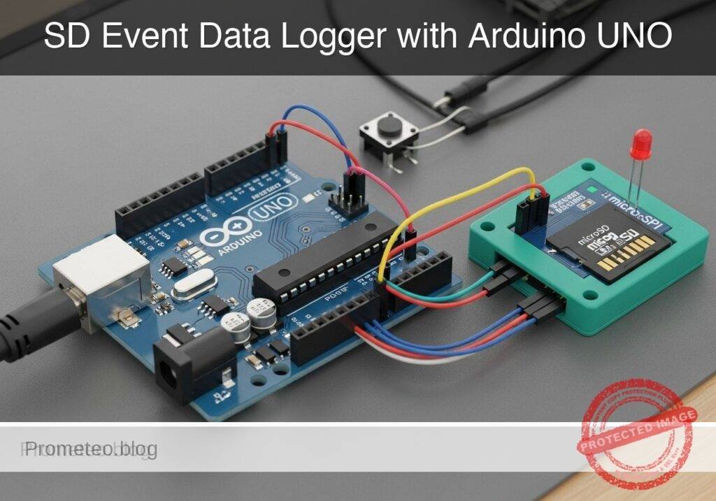
What you’ll build: You will build a standalone, hardware-based event data logger that records manual discrete triggers directly to a local microSD card. Each recorded event is reliably saved with a sequential ID and a precise millisecond-resolution timestamp.
Why it matters / Use cases
- Inventory and Warehouse Counting: Log physical item counts in isolated locations where Wi-Fi or RF infrastructure is unavailable.
- Machine Cycle Tracking: Attach a mechanical limit switch to monitor and log the exact number of times an industrial machine completes a physical cycle.
- Access Logging: Interface with a magnetic reed switch to record the exact timing and frequency of door openings independent of networked security.
- Offline Field Data Collection: Enable environmental researchers to manually register observational events during remote field traverses.
Expected outcome
- A fully debounced mechanical input (e.g., 50ms software debounce) that prevents single presses from registering as multiple false triggers.
- Reliable, offline data persistence to a microSD card via SPI with low-latency (<10ms) write cycles.
- Accurate, sequential event logs formatted as CSV for easy post-processing.
Audience: Embedded systems developers and hardware engineers; Level: Intermediate
Architecture/flow: Mechanical Switch (Input) → Microcontroller (Hardware Interrupt + Debounce Logic) → Millisecond Timer → SPI Interface → microSD Card (CSV Log)
Educational validation note
Before publication, this case passed the Prometeo automated validation gate with status PASS. The validator checked the code blocks, article structure, copy/paste-safe commands and consistency with the supported device catalog.
Published validation evidence
- Automatic result: PASS.
- Parsed structure: 3 sections, 3 tables and 2 code blocks detected before publication.
- Checked code: 1 Python/py_compile, 1 Arduino/arduino-cli compile.
- Supported catalog: the article text was checked against Prometeo’s validation-capable device profiles, and unsupported stacks block publication.
- Report findings: no blocking findings.
This validation confirms syntax and tool compatibility for the published material, but it does not replace physical testing on your exact hardware, wiring and runtime environment.
Educational safety note
This project is an educational prototype, not a certified product. Before powering the setup, verify the pinout of your exact ULX3S board revision, keep FPGA I/O signals at 3.3 V, never connect 5 V directly to I/O pins, disconnect power before changing wiring, and use suitable external supplies for loads, motors or servos while sharing ground only when the wiring requires it.
Conceptual block diagram
High-level view: what enters the system, what each block processes, and what comes out.
Functional architecture
Conceptual signal and responsibility flow between device blocks.

Validation path
Conceptual summary of the tools used to check the published material.

Prerequisites
Before starting this project, ensure you have the following ready:
* A basic understanding of Arduino General Purpose Input/Output (GPIO) operations, specifically digital reads and writes.
* Familiarity with the concept of switch bouncing and why mechanical contacts require software or hardware debouncing.
* A computer running Windows, macOS, or Linux with a command-line interface terminal.
* The arduino-cli (Arduino Command Line Interface) installed and added to your system’s PATH.
* A microSD card (32GB or smaller) freshly formatted to FAT16 or FAT32. The standard Arduino SD library does not support exFAT formats typically found on 64GB+ cards.
Materials
- Microcontroller: Arduino UNO R3 (ATmega328P).
- Storage: microSD SPI module (Ensure it is a module with a built-in 3.3V voltage regulator and logic level shifter, as the Arduino UNO R3 operates at 5V logic).
- Input: Standard 4-pin or 2-pin tactile momentary pushbutton.
- Feedback: 5mm or 3mm Status LED (any color).
- Passives: 1x 220-ohm resistor (for the LED). We will utilize the Arduino’s internal pull-up resistor for the pushbutton.
- Prototyping: Breadboard and assorted male-to-male jumper wires.
- Data/Power: USB Type A to Type B cable.
Setup/Connection
The Arduino UNO R3 communicates with the microSD module using the Serial Peripheral Interface (SPI) protocol. The ATmega328P has dedicated hardware SPI pins which must be used for optimal performance.
MicroSD SPI Module Wiring:
| microSD Module Pin | Arduino UNO R3 Pin | Function Description |
|---|---|---|
| VCC | 5V | Power supply (module steps this down to 3.3V) |
| GND | GND | Common ground |
| MISO | Pin 12 | Master In Slave Out (Data from SD to Arduino) |
| MOSI | Pin 11 | Master Out Slave In (Data from Arduino to SD) |
| SCK | Pin 13 | Serial Clock (Timing signal generated by Arduino) |
| CS | Pin 4 | Chip Select (Signals the SD card to listen) |
Pushbutton Wiring:
* Connect one terminal of the pushbutton to Pin 2 on the Arduino.
* Connect the opposite terminal of the pushbutton to GND.
* Note: No external resistor is required. We will configure Pin 2 using INPUT_PULLUP in the code, which connects an internal 20k-ohm resistor to 5V inside the ATmega328P. When the button is pressed, the pin reads LOW.
Status LED Wiring:
* Connect the longer leg (Anode) of the Status LED to Pin 8 on the Arduino.
* Connect the shorter leg (Cathode) to one end of the 220-ohm resistor.
* Connect the other end of the 220-ohm resistor to GND.
Validated Code
The following section contains the complete source code required for the event logger, as well as a supplementary Python script for analyzing the generated data.
Arduino Sketch: SD_Event_Logger.ino
Create a new directory named SD_Event_Logger and save the following code inside it as SD_Event_Logger.ino.
This code handles the debouncing of the mechanical button, initializes the SPI communication, and appends the data to the SD card. It uses the standard SD.h and SPI.h libraries included with the Arduino core.
Public preview of the validated file. The complete source is shown to members and in PDF/Print.
/*
 * SD Event Data Logger
 * Target: Arduino UNO R3 (ATmega328P)
 * Objective: Log debounced button presses to a microSD card over SPI.
 */

#include <SPI.h>
#include <SD.h>

// Pin Definitions
const int chipSelect = 4;
const int buttonPin = 2;
const int ledPin = 8;

// State Variables
unsigned long eventCount = 0;
int buttonState;
int lastButtonState = HIGH; // HIGH because we use INPUT_PULLUP

// Timing Variables for Debounce
unsigned long lastDebounceTime = 0;
const unsigned long debounceDelay = 50; // 50 milliseconds

void setup() {
  // Initialize Serial for debugging
  Serial.begin(9600);
  while (!Serial) {
    ; // Wait for serial port to connect
  }

  // Configure Pins
  pinMode(buttonPin, INPUT_PULLUP);
  pinMode(ledPin, OUTPUT);

  Serial.println("Initializing SD card...");

  // Initialize SD Card
  if (!SD.begin(chipSelect)) {
    Serial.println("Critical Error: SD card initialization failed!");
    Serial.println("Check wiring, formatting (FAT16/32), and card insertion.");
    // Trap execution in an infinite loop and blink LED rapidly
    while (true) {
      digitalWrite(ledPin, HIGH);
      delay(100);
      digitalWrite(ledPin, LOW);
      delay(100);
    }
  }

  Serial.println("SD card initialized successfully.");

  // Optional: Write a CSV header if the file does not exist
  if (!SD.exists("events.csv")) {
    File dataFile = SD.open("events.csv", FILE_WRITE);
    if (dataFile) {
      dataFile.println("Event_ID,Uptime_ms");
      dataFile.close();
      Serial.println("Created new events.csv with headers.");
    } else {
      Serial.println("Error: Could not create events.csv");
    }
  }
}
// .../*
* SD Event Data Logger
* Target: Arduino UNO R3 (ATmega328P)
* Objective: Log debounced button presses to a microSD card over SPI.
*/
#include <SPI.h>
#include <SD.h>
// Pin Definitions
const int chipSelect = 4;
const int buttonPin = 2;
const int ledPin = 8;
// State Variables
unsigned long eventCount = 0;
int buttonState;
int lastButtonState = HIGH; // HIGH because we use INPUT_PULLUP
// Timing Variables for Debounce
unsigned long lastDebounceTime = 0;
const unsigned long debounceDelay = 50; // 50 milliseconds
void setup() {
// Initialize Serial for debugging
Serial.begin(9600);
while (!Serial) {
; // Wait for serial port to connect
}
// Configure Pins
pinMode(buttonPin, INPUT_PULLUP);
pinMode(ledPin, OUTPUT);
Serial.println("Initializing SD card...");
// Initialize SD Card
if (!SD.begin(chipSelect)) {
Serial.println("Critical Error: SD card initialization failed!");
Serial.println("Check wiring, formatting (FAT16/32), and card insertion.");
// Trap execution in an infinite loop and blink LED rapidly
while (true) {
digitalWrite(ledPin, HIGH);
delay(100);
digitalWrite(ledPin, LOW);
delay(100);
}
}
Serial.println("SD card initialized successfully.");
// Optional: Write a CSV header if the file does not exist
if (!SD.exists("events.csv")) {
File dataFile = SD.open("events.csv", FILE_WRITE);
if (dataFile) {
dataFile.println("Event_ID,Uptime_ms");
dataFile.close();
Serial.println("Created new events.csv with headers.");
} else {
Serial.println("Error: Could not create events.csv");
}
}
}
void loop() {
  // Read the state of the switch into a local variable:
  int reading = digitalRead(buttonPin);

  // Check to see if you just pressed the button
  // (i.e. the input went from HIGH to LOW), and you've waited long enough
  // since the last press to ignore any noise:

  // If the switch changed, due to noise or pressing:
  if (reading != lastButtonState) {
    // reset the debouncing timer
    lastDebounceTime = millis();
  }

  if ((millis() - lastDebounceTime) > debounceDelay) {
    // whatever the reading is at, it's been there for longer than the debounce
    // delay, so take it as the actual current state:

    // if the button state has changed:
    if (reading != buttonState) {
      buttonState = reading;

      // only trigger an event if the new button state is LOW (pressed)
      if (buttonState == LOW) {
        logEventToSD();
      }
    }
}
// save the reading. Next time through the loop, it'll be the lastButtonState:
lastButtonState = reading;
}
void logEventToSD() {
eventCount++;
unsigned long currentTimestamp = millis();
// Open the file. Note that only one file can be open at a time.
// The filename must follow the 8.3 format (max 8 chars name, 3 chars extension)
File dataFile = SD.open("events.csv", FILE_WRITE);
// If the file is available, write to it:
if (dataFile) {
dataFile.print(eventCount);
dataFile.print(",");
dataFile.println(currentTimestamp);
dataFile.close();
// Print to the serial port too:
Serial.print("Logged -> Event: ");
Serial.print(eventCount);
Serial.print(" | Time: ");
Serial.println(currentTimestamp);
// Visual feedback: Quick pulse on the status LED
digitalWrite(ledPin, HIGH);
delay(150); // Short blocking delay is acceptable here to stretch the visual flash
digitalWrite(ledPin, LOW);
}
else {
// If the file isn't open, pop up an error:
Serial.println("Error: Failed to open events.csv for writing.");
// Visual feedback: Three slow flashes indicating a write error
for (int i = 0; i < 3; i++) {
digitalWrite(ledPin, HIGH);
delay(300);
digitalWrite(ledPin, LOW);
delay(300);
}
}
}
Python Analysis Script: analyze_events.py
Save this file on your computer as analyze_events.py. Once you have collected data on your SD card, insert the SD card into your computer and run this script against the events.csv file to parse the basic metrics.
#!/usr/bin/env python3
"""
SD Event Logger Analysis Tool
Objective: Parse the events.csv file generated by the Arduino UNO R3 prototype
and calculate basic duration metrics.
"""

import csv
import sys

def analyze_log(filename):
    try:
        with open(filename, 'r') as file:
            reader = csv.reader(file)
            header = next(reader) # Skip the header row

            events = list(reader)

        total_events = len(events)
        print(f"--- Log Analysis for {filename} ---")
        print(f"Total discrete events logged: {total_events}")

        if total_events >= 2:
            first_time_ms = int(events[0][1])
            last_time_ms = int(events[-1][1])

            duration_ms = last_time_ms - first_time_ms
            duration_sec = duration_ms / 1000.0

            print(f"First event registered at: {first_time_ms} ms")
            print(f"Last event registered at:  {last_time_ms} ms")
            print(f"Total duration between first and last event: {duration_sec:.2f} seconds")

            if duration_sec > 0:
                frequency = total_events / duration_sec
                print(f"Average event frequency: {frequency:.2f} events/second")

    except FileNotFoundError:
        print(f"Error: Could not find '{filename}'. Ensure the path is correct.")
    except ValueError as ve:
        print(f"Error parsing data (likely malformed CSV row): {ve}")
    except Exception as e:
        print(f"An unexpected error occurred: {e}")

if __name__ == "__main__":
    if len(sys.argv) < 2:
        print("Usage: python analyze_events.py <path_to_events.csv>")
    else:
        analyze_log(sys.argv[1])
Build/Flash/Run commands
Use the Arduino CLI to compile and upload the code. Connect your Arduino UNO R3 to your computer via USB. Identify the port (e.g., COM3 on Windows or /dev/ttyACM0 on Linux/macOS).
| Command Purpose | CLI Command |
|---|---|
| Update core index | arduino-cli core update-index |
| Install AVR core | arduino-cli core install arduino:avr |
| Compile sketch | arduino-cli compile --fqbn arduino:avr:uno SD_Event_Logger |
| Upload to board | arduino-cli upload --fqbn arduino:avr:uno --port <PORT> SD_Event_Logger |
| Monitor serial | arduino-cli monitor --port <PORT> --config baudrate=9600 |
Workflow:
1. Open your terminal and navigate to the parent directory containing the SD_Event_Logger folder.
2. Execute the index update and core installation commands to ensure your environment is ready.
3. Compile the sketch using the --fqbn flag for the UNO.
4. Replace <PORT> with your actual serial port and run the upload command.
5. Immediately launch the serial monitor to observe the initialization process.
Step-by-step Validation
Follow these checkpoints to ensure your prototype is functioning correctly.
- SD Initialization Check
- Observation: Open the serial monitor immediately after powering the board.
- Pass condition: The serial monitor displays “Initializing SD card…” followed by “SD card initialized successfully.” The status LED remains off.
- Missing Card Error Handling Check
- Observation: Remove power, eject the microSD card, restore power, and watch the status LED.
- Pass condition: The serial monitor displays “Critical Error: SD card initialization failed!” and the status LED blinks rapidly and continuously.
- Event Trigger Check
- Observation: Reinsert the SD card, power the board, and press the pushbutton once.
- Pass condition: The status LED pulses briefly (150ms). The serial monitor outputs
Logged -> Event: 1 | Time: [timestamp].
- Debounce Logic Check
- Observation: Press and hold the pushbutton, wiggle it slightly without fully releasing, then release.
- Pass condition: Only one event is logged per distinct press-and-release cycle. The event count increments smoothly without skipping numbers (e.g., jumping from 1 to 4).
- Data Integrity Check
- Observation: Power off the Arduino. Remove the SD card, insert it into your computer, and run the Python analysis script:
python analyze_events.py /path/to/SD/events.csv. - Pass condition: The script successfully parses the file, reporting the correct total number of events and calculating the time duration between the first and last press.
- Observation: Power off the Arduino. Remove the SD card, insert it into your computer, and run the Python analysis script:
Troubleshooting
| Symptom | Likely cause | Fix |
|---|---|---|
| SD initialization fails (Rapid |
Find this product and/or books on this topic on Amazon
As an Amazon Associate, I earn from qualifying purchases. If you buy through this link, you help keep this project running.
Quick Quiz

Telecommunications Electronics Engineer and Computer Engineer (official degrees in Spain).