Objective and use case
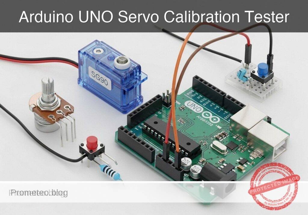
What you’ll build: A standalone, multi-mode servo calibration tester that allows users to manually sweep, automatically center (1500µs), and test the physical limits of standard hobby servos.
Why it matters / Use cases
- RC Vehicle Setup: Perfectly center steering and throttle servos before attaching mechanical servo horns to ensure symmetrical steering geometry.
- Robotic Arm Assembly: Identify exact PWM microsecond values (e.g., 500µs to 2500µs) for physical joint limits to prevent hard mechanical binding and motor burnout in your code.
- Hardware Diagnostics: Quickly test salvaged or suspect servos for dead spots, gear stripping, or excessive jitter without needing to write or flash a custom test script.
- Rapid Prototyping: Establish a permanent benchtop tool to manually actuate linkages and test mechanisms during the mechanical design phase.
Expected outcome
- A reliable hardware control interface utilizing an ADC-read potentiometer for smooth, low-latency manual angle adjustments.
- A software-debounced pushbutton input that seamlessly cycles the microcontroller state machine through three operational modes: Manual Control, Center (90°), and Auto Sweep.
Audience: Hardware hobbyists, robotics developers, and RC builders; Level: Intermediate
Architecture/flow: User Inputs (Potentiometer & Pushbutton) → Microcontroller (ADC Reading & Debounce Logic) → 50Hz PWM Signal Output → Servo Motor Actuation
Educational validation note
Before publication, this case passed the Prometeo automated validation gate with status PASS. The validator checked the code blocks, article structure, copy/paste-safe commands and consistency with the supported device catalog.
Published validation evidence
- Automatic result: PASS.
- Parsed structure: 3 sections, 3 tables and 2 code blocks detected before publication.
- Checked code: 1 Arduino/arduino-cli compile, 1 Bash/copy-paste checks.
- Supported catalog: the article text was checked against Prometeo’s validation-capable device profiles, and unsupported stacks block publication.
- Report findings: no blocking findings.
This validation confirms syntax and tool compatibility for the published material, but it does not replace physical testing on your exact hardware, wiring and runtime environment.
Educational safety note
This prototype is designed strictly for educational laboratory use and benchtop calibration of small, unloaded hobby servos.
* Power Limits: Do not attempt to power high-torque servos (e.g., MG995, MG996R) or multi-servo robotic arms directly from the Arduino UNO’s 5V pin. Doing so will exceed the onboard voltage regulator’s thermal and current limits, potentially destroying the Arduino board or your computer’s USB port.
* Mechanical Hazards: Even small servos can present a pinch hazard if attached to rigid mechanical linkages. Always perform initial calibration tests with the servo horn removed or completely free of mechanical obstructions.
* Suitability: This device is not suitable for, nor intended to be used in, critical control systems, aerospace RC applications, or any environment where failure could result in property damage or injury.
Conceptual block diagram
High-level view: what enters the system, what each block processes, and what comes out.
Functional architecture
Conceptual signal and responsibility flow between device blocks.

Validation path
Conceptual summary of the tools used to check the published material.

Prerequisites
To successfully complete this tutorial, you should have:
* A basic understanding of how to use a terminal or command prompt.
* The Arduino CLI installed on your workstation.
* Familiarity with basic breadboard prototyping (understanding continuity along power rails and terminal strips).
* Understanding of basic Pulse Width Modulation (PWM) concepts, specifically the standard 20 millisecond period and 1–2 millisecond duty cycle used by standard hobby servos.
Materials
For this prototype, you will need the following exact components:
* Arduino UNO R3 (ATmega328P): The primary microcontroller board.
* SG90 Micro Servo: A standard 9-gram hobby servo motor.
* 10 kΩ Potentiometer: A standard rotary potentiometer (linear taper preferred).
* Pushbutton: A standard momentary tactile switch.
* Breadboard and Jumper Wires: For making solderless connections.
* USB Type A to Type B Cable: To connect the Arduino UNO R3 to your computer.
Setup/Connection
The hardware setup is designed to be minimal, utilizing the Arduino’s internal pull-up resistor for the pushbutton to reduce external component count.
Component Wiring Guide:
| Component | Pin / Terminal | Arduino UNO R3 Connection | Notes |
|---|---|---|---|
| SG90 Servo | Brown / Black Wire | GND | Ground connection. |
| SG90 Servo | Red Wire | 5V | Power connection (Unloaded testing only). |
| SG90 Servo | Orange / Yellow Wire | Digital Pin 9 | PWM control signal. |
| Potentiometer | Left Terminal (Pin 1) | 5V | Reference voltage for the analog read. |
| Potentiometer | Middle Terminal (Wiper) | Analog Pin A0 | Variable voltage output (0-5V). |
| Potentiometer | Right Terminal (Pin 3) | GND | Ground reference. |
| Pushbutton | Terminal 1 | Digital Pin 2 | Input signal. |
| Pushbutton | Terminal 2 | GND | Closes circuit to ground when pressed. |
Note on the Pushbutton: We connect the button directly between Digital Pin 2 and Ground. In the software, we will configure Pin 2 with INPUT_PULLUP. This holds the pin at a HIGH logic level (5V) internally. When the button is pressed, it connects the pin to ground, driving the logic level LOW.
Note on the Servo Power: The SG90 is a small servo. When completely unloaded (no mechanical linkages attached), it can safely draw power from the Arduino UNO’s 5V pin, which is supplied by the USB connection. If you attach a mechanical load to the servo, it will draw more current and may cause the Arduino to reset.
Validated Code
The project requires two files. The first is the main Arduino sketch containing the logic. The second is a simple shell script to automate the compilation and upload process using the Arduino CLI.
Main Sketch: servo_tester.ino
Create a directory named servo_tester and save the following code inside it as servo_tester.ino.
Public preview of the validated file. The complete source is shown to members and in PDF/Print.
/*
 * Project: Servo Calibration Tester
 * Target: Arduino UNO R3 (ATmega328P)
 * Description: A multi-mode servo testing tool. Uses a potentiometer for manual
 * control and a pushbutton to cycle between Manual, Center, and Sweep modes.
 */

#include <Servo.h>

// Pin Definitions
const int SERVO_PIN = 9;
const int POT_PIN = A0;
const int BUTTON_PIN = 2;

// Servo Object
Servo testServo;

// State Machine Variables
enum TesterMode {
  MODE_MANUAL = 0,
  MODE_CENTER = 1,
  MODE_SWEEP  = 2
};

TesterMode currentMode = MODE_MANUAL;

// Button Debouncing Variables
int buttonState = HIGH;             // Current reading from the input pin
int lastButtonState = HIGH;         // Previous reading from the input pin
unsigned long lastDebounceTime = 0; // The last time the output pin was toggled
const unsigned long debounceDelay = 50;   // Debounce time in milliseconds

// Servo Sweep Variables
int sweepAngle = 0;
int sweepDirection = 1;
unsigned long lastSweepUpdate = 0;
const unsigned long sweepInterval = 15; // Milliseconds between sweep steps

// Telemetry Variables
unsigned long lastTelemetryTime = 0;
const unsigned long telemetryInterval = 500; // Update Serial every 500ms

void setup() {
  // Initialize Serial Monitor
  Serial.begin(115200);
  while (!Serial) {
    ; // Wait for serial port to connect
  }

  Serial.println("Initializing Servo Calibration Tester...");

  // Configure Pins
  pinMode(POT_PIN, INPUT);
  pinMode(BUTTON_PIN, INPUT_PULLUP); // Use internal pull-up resistor

  // Attach Servo
  // Using standard min/max pulse widths (1000us to 2000us)
  // Some SG90 servos respond better to 500us to 2400us, adjust if necessary.
  testServo.attach(SERVO_PIN, 1000, 2000);

  // Set initial position
  testServo.write(90);
  Serial.println("System Ready. Mode: MANUAL");
}

void loop() {
  handleButton();
  updateServo();
  sendTelemetry();
}

void handleButton() {
  int reading = digitalRead(BUTTON_PIN);

  // Check if the button state has changed
  if (reading != lastButtonState) {
    lastDebounceTime = millis();
  }
// .../*
* Project: Servo Calibration Tester
* Target: Arduino UNO R3 (ATmega328P)
* Description: A multi-mode servo testing tool. Uses a potentiometer for manual
* control and a pushbutton to cycle between Manual, Center, and Sweep modes.
*/
#include <Servo.h>
// Pin Definitions
const int SERVO_PIN = 9;
const int POT_PIN = A0;
const int BUTTON_PIN = 2;
// Servo Object
Servo testServo;
// State Machine Variables
enum TesterMode {
MODE_MANUAL = 0,
MODE_CENTER = 1,
MODE_SWEEP = 2
};
TesterMode currentMode = MODE_MANUAL;
// Button Debouncing Variables
int buttonState = HIGH; // Current reading from the input pin
int lastButtonState = HIGH; // Previous reading from the input pin
unsigned long lastDebounceTime = 0; // The last time the output pin was toggled
const unsigned long debounceDelay = 50; // Debounce time in milliseconds
// Servo Sweep Variables
int sweepAngle = 0;
int sweepDirection = 1;
unsigned long lastSweepUpdate = 0;
const unsigned long sweepInterval = 15; // Milliseconds between sweep steps
// Telemetry Variables
unsigned long lastTelemetryTime = 0;
const unsigned long telemetryInterval = 500; // Update Serial every 500ms
void setup() {
// Initialize Serial Monitor
Serial.begin(115200);
while (!Serial) {
; // Wait for serial port to connect
}
Serial.println("Initializing Servo Calibration Tester...");
// Configure Pins
pinMode(POT_PIN, INPUT);
pinMode(BUTTON_PIN, INPUT_PULLUP); // Use internal pull-up resistor
// Attach Servo
// Using standard min/max pulse widths (1000us to 2000us)
// Some SG90 servos respond better to 500us to 2400us, adjust if necessary.
testServo.attach(SERVO_PIN, 1000, 2000);
// Set initial position
testServo.write(90);
Serial.println("System Ready. Mode: MANUAL");
}
void loop() {
handleButton();
updateServo();
sendTelemetry();
}
void handleButton() {
int reading = digitalRead(BUTTON_PIN);
// Check if the button state has changed
if (reading != lastButtonState) {
lastDebounceTime = millis();
}
  // If the state has been stable longer than the debounce delay
  if ((millis() - lastDebounceTime) > debounceDelay) {
    // If the button state has physically changed
    if (reading != buttonState) {
      buttonState = reading;

      // Only toggle mode if the new button state is LOW (pressed)
      if (buttonState == LOW) {
        cycleMode();
      }
    }
  }
  lastButtonState = reading;
}

void cycleMode() {
  if (currentMode == MODE_MANUAL) {
    currentMode = MODE_CENTER;
    Serial.println(">>> Mode Switched: CENTER (90 deg) <<<");
  } else if (currentMode == MODE_CENTER) {
    currentMode = MODE_SWEEP;
    Serial.println(">>> Mode Switched: AUTO-SWEEP <<<");
  } else {
    currentMode = MODE_MANUAL;
    Serial.println(">>> Mode Switched: MANUAL <<<");
  }
}
void updateServo() {
switch (currentMode) {
case MODE_MANUAL:
{
int potValue = analogRead(POT_PIN);
// Map 10-bit ADC (0-1023) to Servo Angle (0-180)
int targetAngle = map(potValue, 0, 1023, 0, 180);
testServo.write(targetAngle);
}
break;
case MODE_CENTER:
{
testServo.write(90);
}
break;
case MODE_SWEEP:
{
if (millis() - lastSweepUpdate > sweepInterval) {
lastSweepUpdate = millis();
sweepAngle += sweepDirection;
if (sweepAngle >= 180) {
sweepAngle = 180;
sweepDirection = -1;
} else if (sweepAngle <= 0) {
sweepAngle = 0;
sweepDirection = 1;
}
testServo.write(sweepAngle);
}
}
break;
}
}
void sendTelemetry() {
if (millis() - lastTelemetryTime > telemetryInterval) {
lastTelemetryTime = millis();
int currentAngle = testServo.read();
int currentMicroseconds = testServo.readMicroseconds();
Serial.print("Mode: ");
switch (currentMode) {
case MODE_MANUAL: Serial.print("MANUAL\t"); break;
case MODE_CENTER: Serial.print("CENTER\t"); break;
case MODE_SWEEP: Serial.print("SWEEP \t"); break;
}
Serial.print(" | Angle: ");
Serial.print(currentAngle);
Serial.print(" deg | Pulse: ");
Serial.print(currentMicroseconds);
Serial.println(" us");
}
}
Build Script: build.sh
Save this file in the parent directory of servo_tester (or adjust the path accordingly). Make it executable with chmod +x build.sh. Replace <PORT> with your actual serial port (e.g., /dev/ttyACM0 on Linux, COM3 on Windows).
#!/bin/bash

PORT="/dev/ttyACM0" # CHANGE THIS TO YOUR ACTUAL PORT
FQBN="arduino:avr:uno"
SKETCH_DIR="servo_tester"

echo "Updating Arduino core index..."
arduino-cli core update-index

echo "Installing AVR core if not present..."
arduino-cli core install arduino:avr

echo "Compiling sketch..."
arduino-cli compile --fqbn $FQBN $SKETCH_DIR

if [ $? -eq 0 ]; then
    echo "Compilation successful. Uploading to $PORT..."
    arduino-cli upload --fqbn $FQBN --port $PORT $SKETCH_DIR
    echo "Upload complete. Open your serial monitor at 115200 baud."
else
    echo "Compilation failed. Aborting upload."
    exit 1
fi
Build/Flash/Run commands
To compile and upload the firmware manually (if you choose not to use the provided shell script), follow this standardized workflow using the Arduino CLI.
Command Reference
| Action | Command |
|---|---|
| Update Index | arduino-cli core update-index |
| Install Core | arduino-cli core install arduino:avr |
| Compile | arduino-cli compile --fqbn arduino:avr:uno servo_tester |
| Upload | arduino-cli upload --fqbn arduino:avr:uno --port <PORT> servo_tester |
| Monitor | arduino-cli monitor --port <PORT> --config baudrate=115200 |
Workflow
- Identify your port: Connect your Arduino UNO R3 to your computer. Run
arduino-cli board listto find the port identifier (e.g.,/dev/ttyUSB0,/dev/ttyACM0, orCOM3). - Prepare the environment: Run the core update and install commands to ensure your system has the latest ATmega328P toolchain.
- Compile the code: Execute the compile command targeting the
servo_testerdirectory. Verify that no syntax errors are returned. - Flash the device: Execute the upload command, replacing
<PORT>with the port identified in step 1. - Monitor the output: Launch the serial monitor command to observe the boot sequence and telemetry.
Step-by-step Validation
Once the code is uploaded and the serial monitor is open, perform the following grouped checks to validate the system.
Checkpoint 1: Power-on and Initialization
- Action: Reset the Arduino.
- Expected Observation: The serial monitor displays “Initializing Servo Calibration Tester…” followed by “System Ready. Mode: MANUAL”. The servo should snap to an initial 90-degree position.
- Pass Condition: Telemetry begins printing every 500ms showing “Mode: MANUAL”.
Checkpoint 2: Manual Sweep Mode
- Action: While in MANUAL mode, turn the potentiometer from the far left to the far right.
- Expected Observation: The servo horn rotates smoothly in tandem with the potentiometer movement.
- Pass Condition: The serial monitor reports angles changing smoothly from ~0° to ~180°, and pulse widths changing from ~1000 µs to ~2000 µs.
Checkpoint 3: Mode Switching & Centering
- Action: Press the pushbutton once.
- Expected Observation: The serial monitor outputs “>>> Mode Switched: CENTER (90 deg) <<<“. The servo immediately moves to its mechanical center point and locks there.
- Pass Condition: Turning the potentiometer now has no effect on the servo. Telemetry outputs exactly 90 deg and 1500 µs.
Checkpoint 4: Auto-Sweep Mode
- Action: Press the pushbutton a second time.
- Expected Observation: The serial monitor outputs “>>> Mode Switched: AUTO-SWEEP <<<“. The servo begins oscillating back and forth automatically.
- Pass Condition: The telemetry shows the angle incrementing to 180, reversing, decrementing to 0, and repeating.
Checkpoint 5: Return to Manual
- Action: Press the pushbutton a third time.
- Expected Observation: The system returns to MANUAL mode.
- Pass Condition: The servo immediately snaps to the angle currently dictated by the physical position of the potentiometer wiper.
Troubleshooting
| Symptom | Likely Cause | Fix |
|---|---|---|
| Servo jitters erratically | Unstable power supply or poor ground connection. | Ensure all ground pins (Arduino, Potentiometer, Servo) are tied to a common rail. Check jumper wires. |
| Arduino resets when servo moves | Servo is drawing too much current (brownout). | The servo is under mechanical load. Disconnect the load, or power the servo from an external 5V source (sharing grounds). |
| Button press is ignored / double-triggers | Debounce delay is too short or wiring is loose. | Increase debounceDelay in the code to 100ms. Verify the button is firmly seated in the breadboard. |
| Servo only turns 90 degrees total | PWM pulse width mapping mismatch. | Change testServo.attach(SERVO_PIN, 1000, 2000) to testServo.attach(SERVO_PIN, 500, 2400) to match your specific SG90’s limits. |
| Compile error: “Servo.h: No such file” | Missing standard library. | Run arduino-cli lib install Servo to ensure the standard library is available to the compiler. |
Improvements
Once the base prototype is functioning, consider these grouped enhancements:
Hardware Upgrades
* External Power Supply: Add a dedicated 5V, 2A power supply (like a UBEC or bench supply) to the breadboard power rails to test heavy-duty, high-torque metal gear servos without browning out the Arduino.
* OLED Display: Add an I2C 0.96″ OLED screen to display the current angle and pulse width directly on the device, removing the need for a connected computer and serial monitor.
Software Enhancements
* Custom Pulse Width Tuning: Add a fourth mode that uses the potentiometer to finely adjust the minimum and maximum microsecond limits, allowing you to map the exact physical endpoints of off-brand servos.
* Speed Testing Mode: Implement a mode that commands instantaneous 0° to 180° jumps and times the physical response, helping to verify servo speed specifications.
Checklist
- [ ] Arduino CLI is installed and the AVR core is updated.
- [ ] Components are wired according to the Setup table (checking common ground).
- [ ] Pushbutton is wired correctly to utilize the internal pull-up resistor.
- [ ]
servo_tester.inois saved in the correct directory. - [ ] The sketch compiles successfully using
arduino-cli compile. - [ ] The firmware uploads successfully to the correct serial port.
- [ ] The Serial Monitor displays the initialization sequence at 115200 baud.
- [ ] The servo responds smoothly to the potentiometer in MANUAL mode.
- [ ] The pushbutton successfully cycles through all three operational modes.
Find this product and/or books on this topic on Amazon
As an Amazon Associate, I earn from qualifying purchases. If you buy through this link, you help keep this project running.
Quick Quiz

Telecommunications Electronics Engineer and Computer Engineer (official degrees in Spain).