Objective and use case
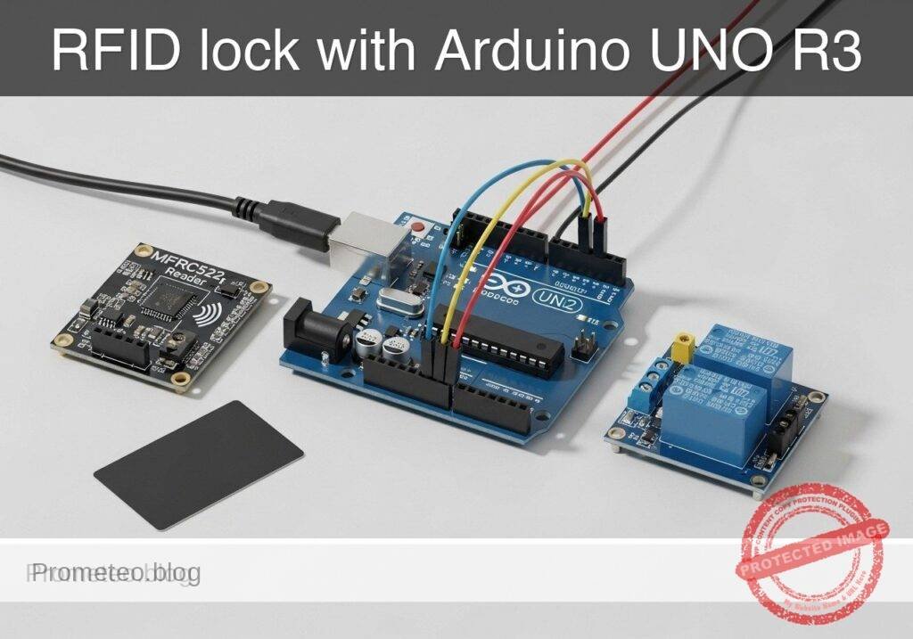
What you’ll build: A basic RFID-controlled door-lock prototype using an Arduino UNO R3, MFRC522 RFID reader, and 1-channel relay. When an authorized card or key fob is detected, the Arduino validates the UID and energizes the relay for 2–5 seconds to drive an electric strike, maglock interface, or low-voltage lock circuit.
Why it matters / Use cases
- Small workshop or cabinet access prototype: Control access to a tool cabinet, lab drawer, or demo enclosure so only known RFID tags can unlock it.
- Entry system concept demonstrator: Practice the same flow used in larger systems: credential read, UID match, timed unlock, and relay-based lock control.
- Electromechanical integration practice: Combine SPI-based RFID sensing with a relay output, moving beyond LED-only projects into real actuator switching.
- Serial-monitor troubleshooting and auditing: Print detected UIDs and allow/deny events over serial at 9600 baud for fast debugging and basic access logs during testing.
Expected outcome
- An RFID card is detected and matched in typically under 200 ms from presentation to decision.
- The relay switches on for a configurable unlock window, commonly 3 seconds, then returns to the locked state automatically.
- Unauthorized tags are rejected immediately, with the UID shown in the Serial Monitor for enrollment or diagnostics.
- The prototype runs comfortably on the UNO’s 16 MHz ATmega328P with low CPU load and no GPU requirement.
Audience: Arduino beginners, students, and embedded/electronics learners building access-control demos; Level: beginner to intermediate
Architecture/flow: MFRC522 reads tag UID over SPI → Arduino UNO compares UID against an authorized list in code → if matched, digital output activates 1-channel relay → relay drives lock interface for a timed interval → Serial Monitor reports allow/deny status and UID values.
Educational validation note
Before publication, this case passed the Prometeo automated validation gate with status PASS. The validator checked the code blocks, article structure, copy/paste-safe commands and consistency with the supported device catalog.
Published validation evidence
- Automatic result: PASS.
- Parsed structure: 3 sections, 1 tables and 24 code blocks detected before publication.
- Checked code: 7 C/C++ static checks, 12 Bash/copy-paste checks.
- Supported catalog: the article text was checked against Prometeo’s validation-capable device profiles, and unsupported stacks block publication.
- Report findings: no blocking findings.
This validation confirms syntax and tool compatibility for the published material, but it does not replace physical testing on your exact hardware, wiring and runtime environment.
Educational safety note
This prototype is for educational low-voltage access-control learning. It is not a certified security product and should not be trusted as the sole protection for homes, businesses, hazardous areas, or life-safety exits.
Important limits and precautions:
- Do not switch mains voltage directly unless you are trained and using properly rated hardware and enclosure practices.
- For student use, validate the relay with a safe low-voltage load first.
- RFID UID-only authorization is weak security.
- Many low-cost RFID tags can be cloned, and UID checking alone is not secure enough for serious protection.
- MFRC522 module voltage matters.
- The reader is a 3.3 V device. Review your specific module’s logic tolerance before connecting it to 5 V Arduino SPI lines.
- Real electric locks may require separate power and protection.
- Follow the lock manufacturer’s current, voltage, and suppression requirements.
- Do not use this project for emergency egress doors or safety-critical locks.
- A software bug, relay failure, power loss, or wiring fault could prevent expected operation.
- Mount and insulate wiring properly.
- Loose wires can cause resets, false triggering, or damaged modules.
Conceptual block diagram
High-level view: what enters the system, what each block processes, and what comes out.
Functional architecture
Conceptual signal and responsibility flow between device blocks.

Validation path
Conceptual summary of the tools used to check the published material.

Prerequisites
Before starting, you should be comfortable with:
- Uploading a sketch to an Arduino UNO
- Opening the Serial Monitor
- Making simple jumper-wire connections on a breadboard or module headers
- Understanding that a relay is an electrically controlled switch
You do not need prior RFID experience. This tutorial explains the minimum required to make a usable access-control prototype.
Materials
Use the exact device family and model requested:
- Arduino UNO R3 (ATmega328P) + MFRC522 RFID module + 1-channel relay module
Recommended full parts list:
- 1 x Arduino UNO R3 (ATmega328P)
- 1 x MFRC522 RFID reader module with matching RFID card or key fob
- 1 x 1-channel relay module
- Prefer a module with transistor driver and opto-isolation or built-in flyback protection
- Coil side usually powered from 5 V
- Jumper wires
- USB cable for Arduino UNO
- Breadboard or stable wiring surface
- Optional but strongly recommended for visible testing:
- 1 x LED
- 1 x 220 ohm resistor
- Optional lock-side educational load:
- Low-voltage lamp, LED indicator, or small DC load controlled through relay contacts
- If you later connect a real electric strike or maglock interface, use the lock manufacturer’s recommended external power source
Setup/Connection
How the system works
The MFRC522 reads the UID of a nearby RFID tag over SPI.
The Arduino compares that UID against a small list of authorized UIDs stored in the sketch.
If the UID matches, the Arduino drives the relay module input for a short time.
The relay contacts can then switch a separate lock circuit or educational test load.
Important voltage note before wiring
The MFRC522 reader is a 3.3 V device. Most common breakout boards expose pins labeled SDA, SCK, MOSI, MISO, RST, 3.3V, and GND. On typical hobby tutorials, the module is powered from 3.3 V, while SPI lines connect directly to the UNO. Many students do this successfully in practice, but electrically the UNO outputs 5 V logic. If your MFRC522 board does not tolerate 5 V on logic pins, use proper level shifting. For a basic educational build, follow the common module usage pattern only if your specific module is known to work that way.
Pin mapping
Use the common MFRC522-to-UNO SPI wiring and one digital pin for the relay.
| Module/Signal | Arduino UNO R3 Pin | Notes |
|---|---|---|
| MFRC522 SDA / SS | D10 | SPI slave select |
| MFRC522 SCK | D13 | SPI clock |
| MFRC522 MOSI | D11 | SPI MOSI |
| MFRC522 MISO | D12 | SPI MISO |
| MFRC522 RST | D9 | Reset pin for reader |
| MFRC522 3.3V | 3.3V | Do not use 5V for reader power |
| MFRC522 GND | GND | Common ground |
| Relay IN | D7 | Relay control signal |
| Relay VCC | 5V | Typical relay module power |
| Relay GND | GND | Common ground |
| Optional LED anode via 220 ohm resistor | D6 | Status indicator |
| Optional LED cathode | GND | LED return |
Text-only connection steps
- Power off the Arduino before making or changing wiring.
- Connect the MFRC522:
- MFRC522 3.3V -> UNO 3.3V
- MFRC522 GND -> UNO GND
- MFRC522 SDA/SS -> UNO D10
- MFRC522 SCK -> UNO D13
- MFRC522 MOSI -> UNO D11
- MFRC522 MISO -> UNO D12
- MFRC522 RST -> UNO D9
- Connect the relay module:
- Relay VCC -> UNO 5V
- Relay GND -> UNO GND
- Relay IN -> UNO D7
- Optional visible status LED:
- UNO D6 -> 220 ohm resistor
- Resistor -> LED anode
- LED cathode -> GND
- If testing relay contacts with a safe low-voltage load:
- Use relay COM and NO for “normally off, on only when unlocked”
- Wire the low-voltage supply path through COM and NO
- Keep the switched circuit electrically appropriate for the relay ratings and module design
Relay contact concept
The relay module has two sides:
- Control side
- VCC, GND, IN
- Connected to Arduino
- Switching side
- COM, NO, NC
- Connected to the lock circuit or test load
For a door unlock action, COM + NO is usually the simplest:
– Idle: open circuit
– Authorized card: relay closes COM to NO for a few seconds
Validated Code
Arduino sketch: rfid_door_lock_relay.ino
Public preview of the validated file. The complete source is shown to members and in PDF/Print.
#include <SPI.h>
#include <MFRC522.h>

static const uint8_t SS_PIN = 10;
static const uint8_t RST_PIN = 9;
static const uint8_t RELAY_PIN = 7;
static const uint8_t STATUS_LED_PIN = 6;

// Many relay modules are ACTIVE LOW.
// Set to true if your relay turns on when the Arduino pin goes LOW.
// Set to false if your relay turns on when the Arduino pin goes HIGH.
static const bool RELAY_ACTIVE_LOW = true;

// Unlock timing in milliseconds
static const unsigned long UNLOCK_TIME_MS = 3000;

// Example authorized UIDs.
// Replace these with the UIDs printed by your own cards during enrollment/testing.
const byte AUTHORIZED_UIDS[][4] = {
  {0xDE, 0xAD, 0xBE, 0xEF},
  {0x12, 0x34, 0x56, 0x78}
};
const size_t AUTHORIZED_UID_COUNT = sizeof(AUTHORIZED_UIDS) / sizeof(AUTHORIZED_UIDS[0]);

MFRC522 mfrc522(SS_PIN, RST_PIN);

bool relayActive = false;
unsigned long relayActivatedAt = 0;
String lastUidString = "";
unsigned long lastScanAt = 0;

// Ignore repeated reads of the same card within this time window
static const unsigned long SAME_CARD_DEBOUNCE_MS = 1500;

void setRelay(bool on) {
  relayActive = on;

  if (RELAY_ACTIVE_LOW) {
    digitalWrite(RELAY_PIN, on ? LOW : HIGH);
  } else {
    digitalWrite(RELAY_PIN, on ? HIGH : LOW);
  }

  digitalWrite(STATUS_LED_PIN, on ? HIGH : LOW);
}
// ...#include <SPI.h>
#include <MFRC522.h>
static const uint8_t SS_PIN = 10;
static const uint8_t RST_PIN = 9;
static const uint8_t RELAY_PIN = 7;
static const uint8_t STATUS_LED_PIN = 6;
// Many relay modules are ACTIVE LOW.
// Set to true if your relay turns on when the Arduino pin goes LOW.
// Set to false if your relay turns on when the Arduino pin goes HIGH.
static const bool RELAY_ACTIVE_LOW = true;
// Unlock timing in milliseconds
static const unsigned long UNLOCK_TIME_MS = 3000;
// Example authorized UIDs.
// Replace these with the UIDs printed by your own cards during enrollment/testing.
const byte AUTHORIZED_UIDS[][4] = {
{0xDE, 0xAD, 0xBE, 0xEF},
{0x12, 0x34, 0x56, 0x78}
};
const size_t AUTHORIZED_UID_COUNT = sizeof(AUTHORIZED_UIDS) / sizeof(AUTHORIZED_UIDS[0]);
MFRC522 mfrc522(SS_PIN, RST_PIN);
bool relayActive = false;
unsigned long relayActivatedAt = 0;
String lastUidString = "";
unsigned long lastScanAt = 0;
// Ignore repeated reads of the same card within this time window
static const unsigned long SAME_CARD_DEBOUNCE_MS = 1500;
void setRelay(bool on) {
relayActive = on;
if (RELAY_ACTIVE_LOW) {
digitalWrite(RELAY_PIN, on ? LOW : HIGH);
} else {
digitalWrite(RELAY_PIN, on ? HIGH : LOW);
}
digitalWrite(STATUS_LED_PIN, on ? HIGH : LOW);
}
void printUid(const MFRC522::Uid *uid) {
  for (byte i = 0; i < uid->size; i++) {
    if (uid->uidByte[i] < 0x10) {
      Serial.print("0");
    }
    Serial.print(uid->uidByte[i], HEX);
    if (i < uid->size - 1) {
      Serial.print(":");
    }
  }
}

String uidToString(const MFRC522::Uid *uid) {
  String s = "";
  for (byte i = 0; i < uid->size; i++) {
    if (uid->uidByte[i] < 0x10) {
      s += "0";
    }
    s += String(uid->uidByte[i], HEX);
    if (i < uid->size - 1) {
      s += ":";
    }
  }
  s.toUpperCase();
  return s;
}
bool isAuthorized(const MFRC522::Uid *uid) {
// This basic example checks only 4-byte UIDs against a fixed list.
if (uid->size != 4) {
return false;
}
for (size_t i = 0; i < AUTHORIZED_UID_COUNT; i++) {
bool match = true;
for (byte j = 0; j < 4; j++) {
if (uid->uidByte[j] != AUTHORIZED_UIDS[i][j]) {
match = false;
break;
}
// ...Library dependency installation
The MFRC522 library is not part of the standard built-in Arduino core, so install it explicitly with Arduino CLI.
arduino-cli lib install "MFRC522"
Build/Flash/Run commands
The following commands match the required Arduino CLI workflow for Arduino UNO R3.
1) Update board index
arduino-cli core update-index
2) Install the AVR core
arduino-cli core install arduino:avr
3) Install the RFID library
arduino-cli lib install "MFRC522"
4) Create the sketch folder
Example directory:
mkdir -p rfid-door-lock-relay
Save the sketch as:
rfid-door-lock-relay/rfid_door_lock_relay.ino
5) Compile
Run this from the parent directory of the sketch folder, or specify the full path.
arduino-cli compile --fqbn arduino:avr:uno rfid-door-lock-relay
6) Find your serial port
On Linux:
arduino-cli board list
On Windows, the port may appear like COM3, COM4, etc.
On Linux, something like /dev/ttyACM0 or /dev/ttyUSB0.
On macOS, something like /dev/cu.usbmodem....
7) Upload
Replace <PORT> with your actual detected port.
arduino-cli upload --fqbn arduino:avr:uno --port <PORT> rfid-door-lock-relay
8) Open serial monitor
arduino-cli monitor --port <PORT> --config baudrate=9600
Step-by-step Validation
This section helps you prove the prototype behaves as intended.
1. Validate the compile stage
Goal:
– Confirm the sketch syntax, board target, and installed library are correct.
Procedure:
1. Run:
bash

arduino-cli compile --fqbn arduino:avr:uno rfid-door-lock-relay
2. Expected result:
– Compilation completes successfully.
– No missing-library errors for MFRC522.h.
What this validates:
– The code is structurally valid for Arduino UNO.
– The library dependency is correctly installed.
What this does not validate:
– Wiring
– Card readability
– Relay polarity
– Physical lock compatibility
2. Validate idle startup behavior
Goal:
– Confirm the board boots and the relay starts in the locked/idle state.
Procedure:
1. Upload the sketch.
2. Open the serial monitor at 9600 baud.
3. Reset the board if needed.
Expected log pattern:
RFID Door Lock Relay Prototype
Present a card/tag to the MFRC522 reader.
Known 4-byte UIDs will activate the relay.
Expected hardware behavior:
– Relay should be idle, not continuously energized.
– Optional LED should be off.
If the relay is ON at idle:
– Your module may use opposite input logic.
– Change:
cpp

static const bool RELAY_ACTIVE_LOW = true;
to:
cpp

static const bool RELAY_ACTIVE_LOW = false;
– Recompile and upload again.
3. Discover your card UID
Goal:
– Read the actual UID of your RFID card or key fob.
Procedure:
1. Present a card to the reader.
2. Watch the serial monitor.
Expected output example:
Card detected. UID=93:4A:1C:7F
ACCESS DENIED - unauthorized card
Record the UID exactly.
Notes:
– The provided code example authorizes only 4-byte UIDs.
– Many common MIFARE cards work this way, but some tags may have different UID lengths.
– For a basic project, use a card with a 4-byte UID if possible.
4. Add your real authorized UID
Goal:
– Make your card unlock the relay.
Procedure:
1. Edit this section:
cpp

const byte AUTHORIZED_UIDS[][4] = {

{0xDE, 0xAD, 0xBE, 0xEF},

{0x12, 0x34, 0x56, 0x78}

};
2. Replace one line with your actual UID bytes.
Example, if the monitor showed 93:4A:1C:7F:
cpp

const byte AUTHORIZED_UIDS[][4] = {

{0x93, 0x4A, 0x1C, 0x7F}

};
3. Recompile and upload.
5. Validate successful access
Goal:
– Confirm that an authorized card activates the relay for the configured duration.
Procedure:
1. Present the authorized card once.
2. Watch the serial output.
3. Listen for relay click and observe optional LED.
Expected output:
Card detected. UID=93:4A:1C:7F
ACCESS GRANTED - relay ON for 3000 ms
Relay OFF - lock returned to idle state
Expected measurable behavior:
– Relay turns on once
– Relay remains active for about 3 seconds
– Relay returns to idle automatically
6. Validate denied access
Goal:
– Ensure an unlisted card does not unlock.
Procedure:
1. Present a different RFID card or fob.
2. Watch the serial monitor.
Expected output:
Card detected. UID=11:22:33:44
ACCESS DENIED - unauthorized card
Expected hardware behavior:
– No unlock relay action
– Optional LED remains off
7. Validate repeat-read handling
Goal:
– Confirm the same card held near the reader does not rapidly retrigger.
Procedure:
1. Hold an authorized card on the reader continuously.
2. Observe behavior for a few seconds.
Expected result:
– One unlock event should occur.
– The debounce window avoids repeated immediate re-triggering of the same read.
Troubleshooting
RFID reader is not detecting any card
Check:
- MFRC522 powered from 3.3 V, not 5 V
- SPI pins are exactly:
- D10 -> SDA/SS
- D11 -> MOSI
- D12 -> MISO
- D13 -> SCK
- D9 -> RST
- Card is compatible with MFRC522 reader frequency and type
- Grounds are common between all modules
Symptom:
– No UID messages at all in Serial Monitor
Likely causes:
– Wrong SPI wiring
– Missing library not likely if code already uploaded
– Reader power issue
– Poor jumper contact
Relay stays on all the time
Likely cause:
– Relay module polarity is opposite your code setting
Fix:
– Change:
cpp

static const bool RELAY_ACTIVE_LOW = true;
to:
cpp

static const bool RELAY_ACTIVE_LOW = false;
– Recompile and upload
Authorized card still says denied
Check:
- UID bytes copied correctly
- Hex values include
0x - Card has 4-byte UID
- You re-uploaded after editing
Serial output shows UID in lowercase or mixed style
That is fine as long as byte values are correct. The matching logic uses raw bytes, not the printed format.
Relay clicks but your lock or test load does not activate
Check the switching side:
- Are you using COM and NO?
- Is the external low-voltage supply present?
- Is the load circuit complete through relay contacts?
- Is the load within relay current/voltage rating?
Arduino resets when relay switches
Possible reasons:
- USB power is weak
- Relay module causes noise or supply dip
- Wiring is too loose or too long
Try:
- Shorter wires
- Better 5 V supply for the relay module if appropriate
- Ensure common ground is solid
- Test with only relay module first, then add lock-side load
Improvements
Once the basic prototype works, these are useful next steps:
Add separate status LEDs
Use:
– Green LED for granted
– Red LED for denied
This improves usability without needing the Serial Monitor.
Add a buzzer
A short beep for valid access and a different beep pattern for denied access makes the system feel more realistic.
Add enrollment mode
Instead of hardcoding UIDs, you could:
– press a button,
– scan a master card,
– store new UIDs in EEPROM.
That would make the prototype more practical.
Add a door sensor
A magnetic reed switch can detect whether the door actually opened or remained open too long.
Improve security logic
This project checks only card UID. For a more realistic system, you could explore:
– sector authentication concepts,
– master/admin cards,
– anti-passback ideas,
– event logging to external storage.
Add a lockout timer
After several denied attempts, the system could ignore scans for 30 seconds and blink a warning LED.
Final Checklist
Use this checklist before calling the project finished:
- [ ] Arduino UNO R3 is wired correctly
- [ ] MFRC522 is powered from 3.3 V
- [ ] Relay module is wired to D7, 5V, and GND
- [ ] Common ground exists between Arduino, RFID module, and relay module
- [ ] Sketch saved as
rfid_door_lock_relay.ino - [ ]
MFRC522library installed with Arduino CLI - [ ] Project compiles with:
bash

arduino-cli compile --fqbn arduino:avr:uno rfid-door-lock-relay - [ ] Project uploads with:
bash

arduino-cli upload --fqbn arduino:avr:uno --port <PORT> rfid-door-lock-relay - [ ] Serial Monitor at 9600 baud shows startup text
- [ ] Unknown card produces ACCESS DENIED
- [ ] Authorized card produces ACCESS GRANTED
- [ ] Relay activates for about 3000 ms
- [ ] Relay returns to idle automatically
- [ ] Low-voltage test load switches correctly through relay contacts
- [ ] You understand this is an educational prototype, not a certified security system
With that, you have a practical RFID door-lock relay prototype that a beginner can actually assemble, test, and extend into a more realistic access-control project.
Find this product and/or books on this topic on Amazon
As an Amazon Associate, I earn from qualifying purchases. If you buy through this link, you help keep this project running.

Telecommunications Electronics Engineer and Computer Engineer (official degrees in Spain).