
Objective and use case
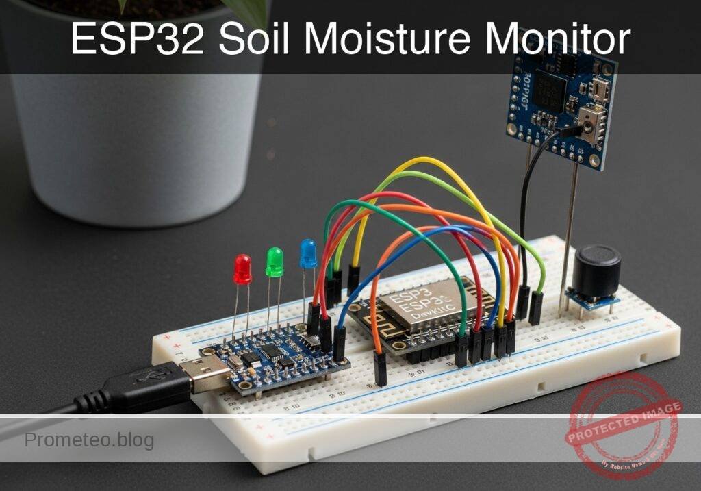
What you’ll build: A continuous plant hydration monitor that measures soil moisture using an analog capacitive sensor, triggering local visual and audible alerts when watering is required.
Why it matters / Use cases
- Agricultural prototyping: Serves as a foundational data-collection node for automated greenhouse irrigation systems, ensuring plants receive water based on objective metrics rather than schedules.
- Hardware longevity: Demonstrates the practical advantage of capacitive sensing over legacy resistive sensors, eliminating rapid galvanic corrosion and soil contamination.
- Preventing plant stress: Replaces guesswork with empirical, real-time soil dielectric measurements to prevent both overwatering (root rot) and underwatering.
- Signal processing: Provides a tangible application for mapping raw, non-linear 12-bit Analog-to-Digital Converter (ADC) values into intuitive 0–100% moisture metrics.
Expected outcome
- Continuous real-time serial output displaying both raw 12-bit ADC values (0–4095) and calculated moisture percentages (0–100%) at a ~1Hz polling rate.
- Immediate visual alert (status LED illumination) and audible cues triggered within milliseconds of the moisture level dropping below the defined threshold.
Audience: IoT hobbyists and embedded developers; Level: Beginner to Intermediate
Architecture/flow: Capacitive Soil Sensor → Microcontroller ADC (12-bit analog read) → Moisture Percentage Mapping → GPIO Output (LED/Buzzer) & Serial Monitor
Educational validation note
Before publication, this case passed the Prometeo automated validation gate with status PASS. For this ESP32 DevKitC profile, the project was checked as a PlatformIO project: the validator extracted platformio.ini and src/main.cpp, created a temporary project and ran pio run against platform = espressif32, board = esp32dev and framework = arduino. It also checked article structure, copy/paste-safe ASCII command options, and unsupported stacks such as direct ESP-IDF or non-scoped ESP32 boards.
Published validation evidence
- Automatic result: PASS.
- Parsed structure: 3 sections, 2 tables and 2 code blocks detected before publication.
- Checked code: 1 PlatformIO config + 1 ESP32 source/pio run.
- Supported catalog: the article text was checked against Prometeo’s validation-capable device profiles, and unsupported stacks block publication.
- Report findings: no blocking findings.
This validation confirms syntax and tool compatibility for the published code, but it does not replace physical testing on your exact ESP32 DevKitC board, wiring, power supply and local WiFi environment.
Educational safety note
This project is an educational prototype, not a certified product. Before powering the setup, verify the pinout of your exact ULX3S board revision, keep FPGA I/O signals at 3.3 V, never connect 5 V directly to I/O pins, disconnect power before changing wiring, and use suitable external supplies for loads, motors or servos while sharing ground only when the wiring requires it.
Conceptual block diagram
High-level view: what enters the system, what each block processes, and what comes out.
Functional architecture
Conceptual control flow: button input, mode selection, PWM timing and servo motion.

Validation path
The automated validation checks syntax, simulation/lint and compatibility with the ULX3S/ECP5 toolchain.

Prerequisites
To successfully complete this tutorial, students should have:
* A basic understanding of the difference between analog signals (continuous voltage levels) and digital signals (binary HIGH/LOW states).
* PlatformIO IDE installed (preferably as a Visual Studio Code extension) or the PlatformIO Core CLI.
* Familiarity with basic breadboarding techniques, including routing power rails and using current-limiting resistors for LEDs.
* Basic C/C++ programming knowledge (variables, if/else conditional logic, and functions).
Materials
You must use the following exact hardware configuration to ensure the provided code and pinouts work without modification:
- ESP32 DevKitC + capacitive soil moisture sensor v1.2 + status LED + piezo buzzer
- 1x 330Ω resistor (Color code: Orange-Orange-Brown, used for the status LED to prevent overcurrent).
- 1x Standard Breadboard (830 tie-points recommended).
- Assorted Dupont jumper wires (Male-to-Male and Male-to-Female depending on your specific sensor header).
- 1x Micro-USB or USB-C cable (ensure it is a data-sync cable, not a charge-only cable).
- A cup of dry soil and a cup of water (for calibration and testing).
Setup/Connection
Proper hardware connection is critical. The ESP32 operates at 3.3V logic levels. The capacitive soil moisture sensor v1.2 includes an onboard voltage regulator, but it is best practice to power it from the ESP32’s 3.3V pin to ensure its analog output never exceeds the ESP32’s maximum ADC input rating (3.3V). Supplying 5V to the sensor could result in analog signals that permanently damage the ESP32’s GPIO pins.
We use GPIO 34 for the analog input. The ESP32 has two internal ADCs. ADC2 is shared with the Wi-Fi radio and cannot be used reliably when Wi-Fi is active. ADC1 (which includes GPIO 34) functions independently of the Wi-Fi stack, making it the standard choice for robust sensor readings.
Wiring Table
| Component | Component Pin / Lead | ESP32 DevKitC Pin | Notes |
|---|---|---|---|
| Capacitive Sensor | VCC / V+ | 3V3 | Power via 3.3V to protect ESP32 ADC. |
| Capacitive Sensor | GND / G | GND | Common ground reference. |
| Capacitive Sensor | AOUT / AU | GPIO 34 | Connected to ADC1_CH6. |
| Status LED | Anode (Long Leg) | GPIO 25 | Connect via the 330Ω resistor. |
| Status LED | Cathode (Short Leg) | GND | Common ground reference. |
| Piezo Buzzer | Positive (+) | GPIO 26 | Driven via ESP32 hardware PWM (LEDC). |
| Piezo Buzzer | Negative (-) | GND | Common ground reference. |
Hardware Note: The piezo buzzer can be active or passive. The code provided uses a Pulse Width Modulation (PWM) signal, which will generate a specific tone on a passive buzzer, and will also successfully trigger an active buzzer by toggling its power rapidly.
Validated Code
The project uses PlatformIO. You will need to configure your environment file and your main application source file.
platformio.ini
Create or replace the contents of your platformio.ini file with the following configuration:
[env:esp32dev]
platform = espressif32
board = esp32dev
framework = arduino
monitor_speed = 115200
src/main.cpp
Copy the following C++ code into your src/main.cpp file. This code implements the continuous analog reading, performs linear interpolation to calculate the moisture percentage, and handles the logic for the hardware alerts.
Public preview of the validated file. The complete source is shown to members and in PDF/Print.
#include <Arduino.h>

// --------------------------------------------------------
// Hardware Pin Definitions
// --------------------------------------------------------
const int MOISTURE_PIN = 34; // ADC1 Channel 6
const int LED_PIN      = 25; // Digital Output for Status LED
const int BUZZER_PIN   = 26; // Digital Output for Piezo Buzzer

// --------------------------------------------------------
// PWM Configuration for Piezo Buzzer
// --------------------------------------------------------
const int PWM_FREQ       = 2000; // 2 kHz audio frequency
const int PWM_CHANNEL    = 0;    // ESP32 Hardware Timer Channel 0
const int PWM_RESOLUTION = 8;    // 8-bit resolution (0-255)

// --------------------------------------------------------
// Calibration Constants
// --------------------------------------------------------
// IMPORTANT: Capacitive sensors output a HIGHER voltage when dry
// and a LOWER voltage when wet. These values represent the 12-bit
// ADC readings (0-4095). You must calibrate these for your specific sensor.
const int DRY_VALUE = 3200;  // Expected ADC reading in completely dry air
const int WET_VALUE = 1400;  // Expected ADC reading submerged in water

// --------------------------------------------------------
// Application Logic Constants
// --------------------------------------------------------
const int ALARM_THRESHOLD_PERCENT = 30; // Trigger alert at or below 30% moisture

void setup() {
    // Initialize Serial Communication for debugging
    Serial.begin(115200);

    // Configure Digital Output Pins
    pinMode(LED_PIN, OUTPUT);
    digitalWrite(LED_PIN, LOW); // Ensure LED is off at boot

    // Configure LEDC PWM peripheral for the Buzzer
    // This allows us to generate a clean square wave for a passive piezo
    ledcSetup(PWM_CHANNEL, PWM_FREQ, PWM_RESOLUTION);
    ledcAttachPin(BUZZER_PIN, PWM_CHANNEL);
    ledcWrite(PWM_CHANNEL, 0); // Ensure buzzer is silent at boot

    Serial.println("=========================================");
    Serial.println(" ESP32 Soil Moisture Monitor Initialized ");
    Serial.println("=========================================");

    // Allow hardware to stabilize
    delay(1000);
}
// ...#include <Arduino.h>
// --------------------------------------------------------
// Hardware Pin Definitions
// --------------------------------------------------------
const int MOISTURE_PIN = 34; // ADC1 Channel 6
const int LED_PIN = 25; // Digital Output for Status LED
const int BUZZER_PIN = 26; // Digital Output for Piezo Buzzer
// --------------------------------------------------------
// PWM Configuration for Piezo Buzzer
// --------------------------------------------------------
const int PWM_FREQ = 2000; // 2 kHz audio frequency
const int PWM_CHANNEL = 0; // ESP32 Hardware Timer Channel 0
const int PWM_RESOLUTION = 8; // 8-bit resolution (0-255)
// --------------------------------------------------------
// Calibration Constants
// --------------------------------------------------------
// IMPORTANT: Capacitive sensors output a HIGHER voltage when dry
// and a LOWER voltage when wet. These values represent the 12-bit
// ADC readings (0-4095). You must calibrate these for your specific sensor.
const int DRY_VALUE = 3200; // Expected ADC reading in completely dry air
const int WET_VALUE = 1400; // Expected ADC reading submerged in water
// --------------------------------------------------------
// Application Logic Constants
// --------------------------------------------------------
const int ALARM_THRESHOLD_PERCENT = 30; // Trigger alert at or below 30% moisture
void setup() {
// Initialize Serial Communication for debugging
Serial.begin(115200);
// Configure Digital Output Pins
pinMode(LED_PIN, OUTPUT);
digitalWrite(LED_PIN, LOW); // Ensure LED is off at boot
// Configure LEDC PWM peripheral for the Buzzer
// This allows us to generate a clean square wave for a passive piezo
ledcSetup(PWM_CHANNEL, PWM_FREQ, PWM_RESOLUTION);
ledcAttachPin(BUZZER_PIN, PWM_CHANNEL);
ledcWrite(PWM_CHANNEL, 0); // Ensure buzzer is silent at boot
Serial.println("=========================================");
Serial.println(" ESP32 Soil Moisture Monitor Initialized ");
Serial.println("=========================================");
// Allow hardware to stabilize
delay(1000);
}
void loop() {
    // 1. Read the raw analog voltage from the sensor
    int rawAdcValue = analogRead(MOISTURE_PIN);

    // 2. Map the raw ADC value to a 0-100 percentage scale.
    // We invert the mapping parameters because DRY is high, WET is low.
    int moisturePercent = map(rawAdcValue, DRY_VALUE, WET_VALUE, 0, 100);

    // 3. Constrain the percentage to strictly 0-100.
    // This prevents negative numbers or values > 100% if the sensor
    // reads slightly outside the hardcoded calibration range.
    moisturePercent = constrain(moisturePercent, 0, 100);

    // 4. Output telemetry to the Serial Monitor
    Serial.print("Raw ADC: ");
    Serial.print(rawAdcValue);
    Serial.print("\t | Moisture: ");
    Serial.print(moisturePercent);
    Serial.println("%");

    // 5. Evaluate the alert threshold
    if (moisturePercent <= ALARM_THRESHOLD_PERCENT) {
        // Condition: Soil is dangerously dry.
        // Action: Flash the LED and pulse the buzzer.

        digitalWrite(LED_PIN, HIGH);
        // Set PWM duty cycle to 50% (128 out of 255) to generate sound
ledcWrite(PWM_CHANNEL, 128);
delay(500); // Wait 500ms
digitalWrite(LED_PIN, LOW);
// Set PWM duty cycle to 0% to silence buzzer
ledcWrite(PWM_CHANNEL, 0);
delay(500); // Wait 500ms
} else {
// Condition: Soil moisture is adequate.
// Action: Keep alerts turned off and delay before next reading.
digitalWrite(LED_PIN, LOW);
ledcWrite(PWM_CHANNEL, 0);
delay(1000); // Poll sensor once per second
}
}
Build/Flash/Run commands
To compile, upload, and monitor the code on your ESP32 DevKitC, use the PlatformIO CLI. Open your terminal in the root directory of your project (where platformio.ini is located) and execute the following commands.
Command Reference
| Action | Command | Purpose |
|---|---|---|
| Build | pio run | Compiles the C++ source code and links the Arduino framework. |
| Upload | pio run --target upload | Flashes the compiled firmware binary to the ESP32. |
| Monitor | pio device monitor | Opens the serial monitor to view the telemetry output. |
Execution Workflow
- Connect the ESP32 DevKitC to your computer via the USB cable. Ensure the CP210x or CH34x drivers are installed if your OS does not recognize the device automatically.
- Run
pio runto verify that there are no syntax errors and that the environment is configured correctly. - Run
pio run --target uploadto flash the device. If the terminal displays “Connecting…” and stalls, you may need to press and hold the “BOOT” button on the ESP32 DevKitC until the flashing process begins. - Run
pio device monitorto observe the serial output. You should immediately see the initialization banner followed by continuous ADC readings.
Step-by-step Validation
Follow these checkpoints to ensure your prototype is fully functional and correctly calibrated.
- Serial Communication Check:
- Action: Open the serial monitor after flashing.
- Expected Observation: The console prints “ESP32 Soil Moisture Monitor Initialized” followed by data lines every second.
- Pass Condition: Text is legible (no garbled characters), confirming the
115200baud rate is correct.
- Dry Air Baseline (0% Calibration):
- Action: Hold the sensor in the open air, touching nothing.
- Expected Observation: The
Raw ADCvalue stabilizes (e.g., around3100to3300). - Pass Condition: Note this number. Update the
DRY_VALUEconstant in the code to match this reading and re-flash the ESP32 if it deviates by more than 100 from the default.
- Water Submersion (100% Calibration):
- Action: Submerge the capacitive sensor in a glass of water up to the marked safety line.
- Expected Observation: The
Raw ADCvalue drops significantly and stabilizes (e.g., around1400). - Pass Condition: The serial monitor outputs
100%. Update theWET_VALUEconstant in the code and re-flash if it does not reach 100%.
- Alert Logic Verification:
- Action: Slowly remove the sensor from the water and wipe it completely dry.
- Expected Observation: The moisture percentage drops. Once it hits 30% or lower, the LED flashes and the buzzer emits a 2000 Hz tone.
- Pass Condition: Visual and audible alerts trigger synchronously exactly when the moisture reads
<= 30%, verifying the logic threshold is functioning safely.
Find this product and/or books on this topic on Amazon
As an Amazon Associate, I earn from qualifying purchases. If you buy through this link, you help keep this project running.
Quick Quiz

Telecommunications Electronics Engineer and Computer Engineer (official degrees in Spain).

