
Objective and use case
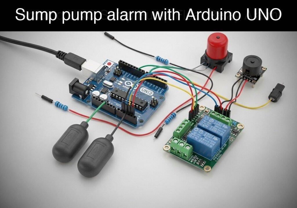
What you’ll build: A dual-float sump pump controller prototype that automates a 5V relay based on water levels and triggers a piezo buzzer alarm if the water remains dangerously high.
Why it matters / Use cases
- Basement flooding prevention: Automatically turns on a pump before water breaches the sump pit, preventing costly water damage.
- Industrial tank monitoring: Maintains fluid levels within a specific safe operating band without short-cycling the pump hardware.
- Agricultural irrigation: Automates the filling or draining of livestock water troughs or hydroponic reservoirs.
- Educational control theory: Introduces hardware hysteresis—using two different thresholds to prevent rapid, damaging mechanical toggling and extend relay lifespan.
Expected outcome
- The 5V relay activates (pump ON) only when water lifts the High float switch.
- The relay remains active even as water drops below the High float, deactivating only when the Low float drops (pump OFF).
- If the High float remains triggered for more than 5 seconds, a piezo buzzer sounds an audible alarm indicating a potential pump failure.
Audience: IoT developers, hardware makers, and home automation enthusiasts; Level: Intermediate
Architecture/flow: Dual Float Switches (Digital Inputs) → Microcontroller (Hysteresis Logic & 5s Timer) → 5V Relay (Pump Control) & Piezo Buzzer (Alarm)
Educational validation note
Before publication, this case passed the Prometeo automated validation gate with status PASS. The validator checked the code blocks, article structure, copy/paste-safe commands and consistency with the supported device catalog.
Published validation evidence
- Automatic result: PASS.
- Parsed structure: 3 sections, 3 tables and 2 code blocks detected before publication.
- Checked code: 2 Arduino/arduino-cli compile.
- Supported catalog: the article text was checked against Prometeo’s validation-capable device profiles, and unsupported stacks block publication.
- Report findings: no blocking findings.
This validation confirms syntax and tool compatibility for the published material, but it does not replace physical testing on your exact hardware, wiring and runtime environment.
Educational safety note
This project is a low-voltage educational prototype, not a certified product. Before powering the setup, verify the wiring of your Arduino UNO R3, avoid shorting 5 V, GND or digital pins, disconnect power before changing connections, and use proper interface modules for relays, motors or external loads.
Conceptual block diagram
High-level view: what enters the system, what each block processes, and what comes out.
Functional architecture
Conceptual signal and responsibility flow between device blocks.

Validation path
Conceptual summary of the tools used to check the published material.

Prerequisites
Before starting this tutorial, you should have:
* A basic understanding of digital logic (HIGH/LOW states).
* Familiarity with the concept of pull-up resistors (specifically the Arduino’s internal INPUT_PULLUP).
* A computer with the command-line interface (Terminal/Command Prompt) available.
* Arduino CLI installed and added to your system’s PATH.
Materials
To build this specific prototype, you will need the following exact components:
* Microcontroller: Arduino UNO R3 (ATmega328P)
* Sensors: 2x Mechanical float switches (vertical or horizontal, standard magnetic reed switch type)
* Actuator: 1x 5 V Relay module (standard 1-channel, opto-isolated)
* Alarm: 1x Piezo buzzer (Active 5V buzzer preferred, though passive works with the tone() function used in this code)
* Prototyping: 1x Solderless breadboard
* Wiring: Assorted male-to-male and male-to-female jumper wires
* Power: Standard USB A-to-B cable for programming and powering the Arduino
Setup/Connection
This project relies on the Arduino’s internal pull-up resistors for the float switches. This simplifies wiring by eliminating the need for external resistors. When the float switch is open, the Arduino pin reads HIGH. When the water rises and closes the float switch, it connects the pin to Ground, and the Arduino reads LOW.
Most standard 5 V relay modules are “Active LOW,” meaning that pulling the signal pin to LOW energizes the relay coil, and setting it HIGH turns it off. The code provided accounts for this common behavior.
Pin Mapping Table
| Component | Arduino UNO R3 Pin | Component Connection | Notes |
|---|---|---|---|
| Low Float Switch | Digital Pin 2 | Wire 1 | Wire 2 goes to Arduino GND |
| High Float Switch | Digital Pin 3 | Wire 1 | Wire 2 goes to Arduino GND |
| 5 V Relay Module | Digital Pin 4 | IN / Signal | VCC to 5V, GND to GND |
| Piezo Buzzer | Digital Pin 5 | Positive (+) | Negative (-) to Arduino GND |
Note on Float Switch Orientation: Mechanical float switches usually contain a magnetic reed switch and a floating ring. You can often remove the C-clip at the bottom to flip the float ring. For this project, configure both switches so they are Open when resting (down) and Closed when floating (up).
Validated Code
The project uses two separate code files. The first is a hardware test to ensure your relay and buzzer are wired correctly. The second is the main controller logic.
Hardware Test Sketch (hardware_test.ino)
Create a directory named hardware_test and save the following code as hardware_test.ino inside it. This sketch toggles the relay and buzzer sequentially so you can verify your wiring before adding the complexity of the float sensors.
/*
 * hardware_test.ino
 * Basic validation sketch to verify Relay and Buzzer connections.
 */

const int RELAY_PIN = 4;
const int BUZZER_PIN = 5;

// Most 5V relay modules are Active LOW.
const int RELAY_ON = LOW;
const int RELAY_OFF = HIGH;

void setup() {
  Serial.begin(9600);
  Serial.println("Starting Hardware Test...");

  pinMode(RELAY_PIN, OUTPUT);
  pinMode(BUZZER_PIN, OUTPUT);

  // Ensure relay and buzzer are OFF initially
  digitalWrite(RELAY_PIN, RELAY_OFF);
  digitalWrite(BUZZER_PIN, LOW);
}

void loop() {
  Serial.println("Testing Relay: ON");
  digitalWrite(RELAY_PIN, RELAY_ON);
  delay(2000);

  Serial.println("Testing Relay: OFF");
  digitalWrite(RELAY_PIN, RELAY_OFF);
  delay(2000);

  Serial.println("Testing Buzzer: ON");
  tone(BUZZER_PIN, 1000); // Play 1kHz tone
  delay(1000);

  Serial.println("Testing Buzzer: OFF");
  noTone(BUZZER_PIN);
  delay(2000);

  Serial.println("Hardware test cycle complete. Repeating...");
  Serial.println("----------------------------------------");
}
Main Controller Logic (sump_controller.ino)
Create a directory named sump_controller and save the following code as sump_controller.ino. This code implements the hysteresis logic and the non-blocking alarm timer.
Public preview of the validated file. The complete source is shown to members and in PDF/Print.
/*
 * sump_controller.ino
 * Dual-float sump pump controller with hysteresis and high-water alarm.
 * Target: Arduino UNO R3 (ATmega328P)
 */

// --- Pin Definitions ---
const int LOW_FLOAT_PIN = 2;
const int HIGH_FLOAT_PIN = 3;
const int RELAY_PIN = 4;
const int BUZZER_PIN = 5;

// --- Logic Definitions ---
// Using INPUT_PULLUP: Switch closed (floating up) connects to GND (LOW)
const int FLOAT_TRIGGERED = LOW;
const int FLOAT_RESTING = HIGH;

// Standard 5V relay modules are typically Active LOW
const int RELAY_ON = LOW;
const int RELAY_OFF = HIGH;

// --- Alarm Configuration ---
// Time in milliseconds before triggering alarm if High Float stays triggered
const unsigned long ALARM_DELAY_MS = 5000;

// --- State Variables ---
bool pumpIsActive = false;
bool alarmIsActive = false;
unsigned long highFloatStartTime = 0;

void setup() {
  Serial.begin(9600);
  while (!Serial) { ; } // Wait for serial port to connect

  Serial.println("Initializing Sump Pump Controller...");

  // Configure float switch pins with internal pull-ups
  pinMode(LOW_FLOAT_PIN, INPUT_PULLUP);
  pinMode(HIGH_FLOAT_PIN, INPUT_PULLUP);

  // Configure output pins
  pinMode(RELAY_PIN, OUTPUT);
  pinMode(BUZZER_PIN, OUTPUT);

  // Set initial safe states
  digitalWrite(RELAY_PIN, RELAY_OFF);
  noTone(BUZZER_PIN);

  Serial.println("System Ready.");
  Serial.println("-----------------------------------");
}
// .../*
* sump_controller.ino
* Dual-float sump pump controller with hysteresis and high-water alarm.
* Target: Arduino UNO R3 (ATmega328P)
*/
// --- Pin Definitions ---
const int LOW_FLOAT_PIN = 2;
const int HIGH_FLOAT_PIN = 3;
const int RELAY_PIN = 4;
const int BUZZER_PIN = 5;
// --- Logic Definitions ---
// Using INPUT_PULLUP: Switch closed (floating up) connects to GND (LOW)
const int FLOAT_TRIGGERED = LOW;
const int FLOAT_RESTING = HIGH;
// Standard 5V relay modules are typically Active LOW
const int RELAY_ON = LOW;
const int RELAY_OFF = HIGH;
// --- Alarm Configuration ---
// Time in milliseconds before triggering alarm if High Float stays triggered
const unsigned long ALARM_DELAY_MS = 5000;
// --- State Variables ---
bool pumpIsActive = false;
bool alarmIsActive = false;
unsigned long highFloatStartTime = 0;
void setup() {
Serial.begin(9600);
while (!Serial) { ; } // Wait for serial port to connect
Serial.println("Initializing Sump Pump Controller...");
// Configure float switch pins with internal pull-ups
pinMode(LOW_FLOAT_PIN, INPUT_PULLUP);
pinMode(HIGH_FLOAT_PIN, INPUT_PULLUP);
// Configure output pins
pinMode(RELAY_PIN, OUTPUT);
pinMode(BUZZER_PIN, OUTPUT);
// Set initial safe states
digitalWrite(RELAY_PIN, RELAY_OFF);
noTone(BUZZER_PIN);
Serial.println("System Ready.");
Serial.println("-----------------------------------");
}
void loop() {
  // 1. Read the current state of both float switches
  int lowFloatState = digitalRead(LOW_FLOAT_PIN);
  int highFloatState = digitalRead(HIGH_FLOAT_PIN);

  // 2. Evaluate Hysteresis Logic for the Pump
  if (highFloatState == FLOAT_TRIGGERED) {
    // Water has reached the top float. Turn pump ON.
    if (!pumpIsActive) {
      pumpIsActive = true;
      digitalWrite(RELAY_PIN, RELAY_ON);
      Serial.println("ACTION: High level reached. Pump turned ON.");
    }
  }
  else if (lowFloatState == FLOAT_RESTING) {
    // Water has dropped below the bottom float. Turn pump OFF.
    if (pumpIsActive) {
      pumpIsActive = false;
      digitalWrite(RELAY_PIN, RELAY_OFF);
      Serial.println("ACTION: Low level cleared. Pump turned OFF.");
    }
  }
  // Note: If water is between the two floats, pumpIsActive retains its previous state.
  // This is the core of hysteresis.

  // 3. Evaluate Alarm Logic (Non-blocking timer)
  if (highFloatState == FLOAT_TRIGGERED) {
// If this is the first moment we see the high float triggered, record the time
if (highFloatStartTime == 0) {
highFloatStartTime = millis();
}
// Check if the high float has been triggered longer than the allowed delay
if ((millis() - highFloatStartTime >= ALARM_DELAY_MS) && !alarmIsActive) {
alarmIsActive = true;
tone(BUZZER_PIN, 2000); // 2kHz warning tone
Serial.println("ALARM: Water level critically high! Pump may be failing.");
}
} else {
// Water is no longer at the high float. Reset alarm states.
if (highFloatStartTime != 0 || alarmIsActive) {
highFloatStartTime = 0;
alarmIsActive = false;
noTone(BUZZER_PIN);
Serial.println("STATUS: High water condition cleared. Alarm reset.");
}
}
// Small delay to debounce switch chattering from simulated water ripples
delay(100);
}
Understanding the Code Logic
The main controller sketch relies on two fundamental engineering concepts:
- Hysteresis: If we only used one float switch, ripples in the water would cause the switch to rapidly bounce between ON and OFF. This “short-cycling” destroys mechanical relays and pump motors. By using a High float to turn the pump ON, and a completely separate Low float to turn the pump OFF, the water level must travel the physical distance between the two switches before the state changes.
- Non-blocking Timers: Instead of using
delay(5000)for the alarm—which would freeze the entire Arduino and stop it from checking the floats—the code usesmillis(). It records a timestamp when the high float triggers (highFloatStartTime) and continually subtracts it from the current time. If the difference exceeds 5000 milliseconds, the alarm sounds, all while the Arduino continues to evaluate the pump logic 10 times a second.
Build/Flash/Run commands
Use the Arduino CLI to compile and upload the code to your Arduino UNO R3.
Command Reference Table
| Task | Command |
|---|---|
| Update Index | arduino-cli core update-index |
| Install AVR Core | arduino-cli core install arduino:avr |
| Compile Code | arduino-cli compile --fqbn arduino:avr:uno sump_controller |
| Upload to Board | arduino-cli upload --fqbn arduino:avr:uno --port <PORT> sump_controller |
| Serial Monitor | arduino-cli monitor --port <PORT> --config baudrate=9600 |
Note: Replace <PORT> with your actual serial port (e.g., COM3 on Windows, /dev/ttyACM0 on Linux, or /dev/cu.usbmodem14101 on macOS).
Execution Workflow
- Open your terminal and navigate to the directory containing your
sump_controllerfolder. - Update your core index and ensure the AVR architecture is installed (first two commands in the table).
- Compile the sketch to verify there are no syntax errors.
- Connect your Arduino UNO R3 via USB.
- Upload the compiled code to the board.
- Launch the serial monitor to view the system logs and begin physical validation.
Step‑by‑step Validation
With the serial monitor open, manually manipulate the physical float switches to simulate water rising and falling.
- Initial State (Empty Pit)
- Action: Leave both floats hanging down (resting/open).
- Expected Observation: Serial monitor shows “System Ready.” Relay is silent. Buzzer is silent.
- Pass Condition: Pin 4 is HIGH (Relay OFF), Pin 5 is LOW.
- Water Rising (Mid-level)
- Action: Lift the Low float up (closed). Leave the High float down.
- Expected Observation: No change in relay or buzzer.
- Pass Condition: The system waits for the High float. Hysteresis prevents premature activation.
- Water Rising (High-level / Pump Activation)
- Action: Keep the Low float up, and lift the High float up.
- Expected Observation: A distinct “click” from the relay module. Serial monitor logs “ACTION: High level reached. Pump turned ON.”
- Pass Condition: Relay indicator LED turns on. Pump logic is successfully engaged.
- Alarm Trigger (Pump Failure Simulation)
- Action: Hold both floats up for more than 5 seconds.
- Expected Observation: After exactly 5 seconds, the piezo buzzer emits a loud 2kHz tone. Serial logs “ALARM: Water level critically high!”.
- Pass Condition: Non-blocking timer successfully evaluates the elapsed time and triggers the warning.
- Water Receding (Mid-level)
- Action: Drop the High float down (open). Keep the Low float up.
- Expected Observation: Buzzer stops immediately. Serial logs “STATUS: High water condition cleared.” Crucially, the relay remains ON (clicked).
- Pass Condition: Hysteresis logic holds the pump active to continue draining the pit.
- Water Receding (Empty Pit)
- Action: Drop the Low float down (open).
- Expected Observation: Relay “clicks” off. Serial logs “ACTION: Low level cleared. Pump turned OFF.”
- Pass Condition: System returns to the initial safe state.
Quick Quiz
Troubleshooting
| Symptom | Likely Cause | Fix |
|---|---|---|
| Relay turns on when floats are DOWN, off when UP | Float switch C-clip is inverted (Normally Closed instead of Normally Open). | Remove the bottom C-clip on the float, flip the magnetic ring upside down, and replace the clip. |
| Relay LED lights up, but no “click” is heard | Insufficient power to the relay coil. | Ensure the relay module’s VCC is connected to the Arduino’s 5V pin, not the 3.3V pin. |
| Pump short-cycles rapidly (Relay chatters) | The float switches are wired backward to the Arduino pins. | Swap the wires on pins D |
Find this product and/or books on this topic on Amazon
As an Amazon Associate, I earn from qualifying purchases. If you buy through this link, you help keep this project running.

Telecommunications Electronics Engineer and Computer Engineer (official degrees in Spain).

