
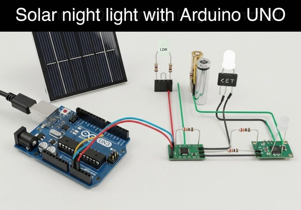
Objective and use case
What you’ll build: You will build an automated solar night light controller that activates a high-power LED array at dusk. It uses an LDR for ambient light sensing and a resistor voltage divider to actively monitor and protect a 12V battery from deep discharge.
Why it matters / Use cases
- Battery Protection: Actively monitors battery health and cuts the load when voltage drops below safe thresholds (e.g., < 10.5V), preventing permanent damage to lead-acid or lithium-ion cells.
- Energy Efficiency: Utilizes an LDR with software hysteresis to ensure lighting activates only when truly needed, preventing rapid flickering and power waste during twilight hours.
- Off-Grid Automation: Forms the core autonomous logic for remote bus stop lighting, garden sheds, or pathway safety lights operating entirely without mains power.
- Scalable Power Control: Uses a logic-level N-channel MOSFET to demonstrate how a low-power 5V microcontroller can safely switch large DC loads (up to 5A/60W).
Expected outcome
- Accurate Voltage Reading: The Arduino will correctly scale and measure the 12V battery voltage via the divider circuit with a < 0.1V margin of error.
- Reliable Actuation: Seamlessly switches the high-power LED load with < 10ms latency once the LDR detects the target darkness threshold.
- Battery Preservation: Successfully disconnects the LED array automatically when battery capacity falls to the critical 10.5V safety limit.
Audience: IoT developers, hardware makers, and off-grid enthusiasts; Level: Intermediate
Architecture/flow: LDR & Voltage Divider (Sensors) → Arduino ADC (Logic/Processing) → N-Channel MOSFET (Switch) → 12V LED Array (Output)
Educational validation note
Before publication, this case passed the Prometeo automated validation gate with status PASS. The validator checked the code blocks, article structure, copy/paste-safe commands and consistency with the supported device catalog.
Published validation evidence
- Automatic result: PASS.
- Parsed structure: 3 sections, 2 tables and 2 code blocks detected before publication.
- Checked code: 1 Python/py_compile, 1 Arduino/arduino-cli compile.
- Supported catalog: the article text was checked against Prometeo’s validation-capable device profiles, and unsupported stacks block publication.
- Report findings: no blocking findings.
This validation confirms syntax and tool compatibility for the published material, but it does not replace physical testing on your exact hardware, wiring and runtime environment.
Educational safety note
This project is a low-voltage educational prototype, not a certified product. Before powering the setup, verify the wiring of your Arduino UNO R3, avoid shorting 5 V, GND or digital pins, disconnect power before changing connections, and use proper interface modules for relays, motors or external loads.
Conceptual block diagram
High-level view: what enters the system, what each block processes, and what comes out.
Functional architecture
Conceptual signal and responsibility flow between device blocks.

Validation path
Conceptual summary of the tools used to check the published material.

Prerequisites
To successfully complete this tutorial, you should have a basic understanding of Ohm’s Law (specifically voltage divider calculations), fundamental C++ programming for Arduino (variables, if/else statements, millis() for timing), and familiarity with operating a command-line interface. You must have the Arduino CLI installed and configured on your host computer.
Materials
You will need the following exact components to build this prototype:
- Microcontroller: Arduino UNO R3 (ATmega328P)
- Light Sensor: 1x Standard LDR (Photoresistor)
- MOSFET: 1x IRLZ44N (Logic-Level N-Channel Power MOSFET)
- Resistors (1/4 Watt):
- 1x 30kΩ (Battery divider R1)
- 2x 10kΩ (Battery divider R2, LDR pull-down)
- 1x 10kΩ (MOSFET Gate pull-down)
- 1x 220Ω (MOSFET Gate current limiter)
- Load: 1x 12V LED Array or 12V LED Strip (Max 2 Amps for breadboard testing)
- Power Source: 1x 12V Battery (e.g., 3S Li-ion pack or 12V Sealed Lead-Acid battery)
- Prototyping: 1x Breadboard, assorted male-to-male jumper wires
Setup/Connection
Because the Arduino UNO R3 operates at 5V, it cannot directly measure a 12V battery or drive a 12V load. We must use specific interface circuits.
1. The Battery Voltage Divider
The Arduino ADC can only measure up to 5V. To measure a 12V battery (which can reach up to 14.4V when charging), we use a voltage divider. Connect the 30kΩ resistor (R1) to the Battery Positive (BAT+) terminal. Connect the other end of the 30kΩ resistor to Arduino pin A0. Connect the 10kΩ resistor (R2) from Arduino pin A0 to Ground (GND).
Formula: Vout = Vin * (R2 / (R1 + R2)). At 20V input, A0 sees exactly 5V. The scaling factor in code will be 4.0.
2. The LDR Divider
Connect one leg of the LDR to the Arduino 5V pin. Connect the other leg of the LDR to Arduino pin A1. Connect a 10kΩ resistor from Arduino pin A1 to Ground (GND).
Behavior: In bright light, LDR resistance drops, pulling A1 close to 5V. In darkness, LDR resistance rises, and the 10kΩ resistor pulls A1 close to 0V.
3. The MOSFET LED Driver
Hold the IRLZ44N MOSFET so the metal tab is in the back and text faces you. The pins from left to right are Gate (1), Drain (2), and Source (3).
* Connect Arduino Pin 9 to a 220Ω resistor, then to the MOSFET Gate.
* Connect a 10kΩ resistor from the MOSFET Gate directly to Ground (this prevents the LED from flashing while the Arduino boots up).
* Connect the MOSFET Source to Ground.
* Connect the MOSFET Drain to the Negative (Cathode) wire of your 12V LED Array.
* Connect the Positive (Anode) wire of your 12V LED Array directly to the Battery Positive (BAT+) terminal.
4. Common Ground
Ensure the Arduino GND, the Battery Negative terminal, the MOSFET Source, and all divider ground connections are tied together on the breadboard’s negative rail.
Pinout Mapping Table
| Arduino UNO R3 Pin | Component Connection | Function |
|---|---|---|
| A0 | Junction of 30kΩ and 10kΩ resistors | Battery Voltage Sensing |
| A1 | Junction of LDR and 10kΩ resistor | Ambient Light Sensing |
| Pin 9 (PWM) | 220Ω resistor → MOSFET Gate | LED Brightness / Switching |
| 5V | LDR top leg | Reference voltage for LDR |
| GND | Common Ground Rail | System Return / Reference |
| VIN | Not connected in this test | Power Arduino via USB for testing |
Validated Code
The following section contains two files. The first is the C++ firmware for the Arduino UNO R3. The second is an optional Python script that runs on your computer to log the serial data from the Arduino into a CSV file, which is highly useful for validating the battery discharge curve and switching points.
Arduino Firmware: solar_night_light.ino
Create a folder named solar_night_light and place this code inside a file named solar_night_light.ino.
Public preview of the validated file. The complete source is shown to members and in PDF/Print.
/*
 * Solar Night Light Controller
 * Target: Arduino UNO R3 (ATmega328P)
 * Purpose: Controls a 12V LED via MOSFET based on LDR light levels,
 *          incorporating Low Voltage Disconnect (LVD) for battery protection.
 */

// --- Hardware Pins ---
const int PIN_BATTERY_SENSE = A0;
const int PIN_LIGHT_SENSE   = A1;
const int PIN_LED_DRIVE     = 9;

// --- Calibration & Thresholds ---
// Voltage Divider: R1 = 30k, R2 = 10k. Ratio = (30+10)/10 = 4.0
const float VOLTAGE_DIVIDER_RATIO = 4.0;
const float ADC_REFERENCE_VOLTAGE = 5.0;
const float ADC_MAX_VALUE = 1023.0;

// Battery Thresholds (12V Lead-Acid / 3S Li-ion example)
const float BATT_LVD_DISCONNECT = 10.5; // Turn off below 10.5V
const float BATT_LVD_RECONNECT  = 11.5; // Require 11.5V to turn back on

// Light Thresholds (0-1023). Higher value = brighter ambient light.
const int LIGHT_THRESHOLD_DARK  = 300;  // Below this is considered night
const int LIGHT_THRESHOLD_LIGHT = 450;  // Above this is considered day

// --- System State ---
enum SystemState {
  STATE_DAYTIME,
  STATE_NIGHT_ON,
  STATE_LOW_BATTERY
};

SystemState currentState = STATE_DAYTIME;

// --- Timing ---
unsigned long lastLogTime = 0;
const unsigned long LOG_INTERVAL_MS = 1000;

void setup() {
  Serial.begin(115200);

  pinMode(PIN_BATTERY_SENSE, INPUT);
  pinMode(PIN_LIGHT_SENSE, INPUT);

  // Initialize MOSFET drive pin
  pinMode(PIN_LED_DRIVE, OUTPUT);
  analogWrite(PIN_LED_DRIVE, 0); // Ensure LED is OFF at boot

  Serial.println("Solar Night Light Controller Initialized.");
  Serial.println("Timestamp_ms,Battery_V,Light_ADC,State,PWM_Out");
}

void loop() {
  // 1. Read Sensors
  int rawBatteryADC = analogRead(PIN_BATTERY_SENSE);
  int rawLightADC = analogRead(PIN_LIGHT_SENSE);

  // 2. Calculate Real Voltage
  float pinVoltage = (rawBatteryADC / ADC_MAX_VALUE) * ADC_REFERENCE_VOLTAGE;
  float batteryVoltage = pinVoltage * VOLTAGE_DIVIDER_RATIO;

  // 3. State Machine Logic
  switch (currentState) {

    case STATE_DAYTIME:
      // Transition to NIGHT if it gets dark AND battery is healthy
      if (rawLightADC < LIGHT_THRESHOLD_DARK) {
        if (batteryVoltage > BATT_LVD_RECONNECT) {
          currentState = STATE_NIGHT_ON;
        } else {
          currentState = STATE_LOW_BATTERY; // Too dark, but battery is dead
        }
// .../*
* Solar Night Light Controller
* Target: Arduino UNO R3 (ATmega328P)
* Purpose: Controls a 12V LED via MOSFET based on LDR light levels,
* incorporating Low Voltage Disconnect (LVD) for battery protection.
*/
// --- Hardware Pins ---
const int PIN_BATTERY_SENSE = A0;
const int PIN_LIGHT_SENSE = A1;
const int PIN_LED_DRIVE = 9;
// --- Calibration & Thresholds ---
// Voltage Divider: R1 = 30k, R2 = 10k. Ratio = (30+10)/10 = 4.0
const float VOLTAGE_DIVIDER_RATIO = 4.0;
const float ADC_REFERENCE_VOLTAGE = 5.0;
const float ADC_MAX_VALUE = 1023.0;
// Battery Thresholds (12V Lead-Acid / 3S Li-ion example)
const float BATT_LVD_DISCONNECT = 10.5; // Turn off below 10.5V
const float BATT_LVD_RECONNECT = 11.5; // Require 11.5V to turn back on
// Light Thresholds (0-1023). Higher value = brighter ambient light.
const int LIGHT_THRESHOLD_DARK = 300; // Below this is considered night
const int LIGHT_THRESHOLD_LIGHT = 450; // Above this is considered day
// --- System State ---
enum SystemState {
STATE_DAYTIME,
STATE_NIGHT_ON,
STATE_LOW_BATTERY
};
SystemState currentState = STATE_DAYTIME;
// --- Timing ---
unsigned long lastLogTime = 0;
const unsigned long LOG_INTERVAL_MS = 1000;
void setup() {
Serial.begin(115200);
pinMode(PIN_BATTERY_SENSE, INPUT);
pinMode(PIN_LIGHT_SENSE, INPUT);
// Initialize MOSFET drive pin
pinMode(PIN_LED_DRIVE, OUTPUT);
analogWrite(PIN_LED_DRIVE, 0); // Ensure LED is OFF at boot
Serial.println("Solar Night Light Controller Initialized.");
Serial.println("Timestamp_ms,Battery_V,Light_ADC,State,PWM_Out");
}
void loop() {
// 1. Read Sensors
int rawBatteryADC = analogRead(PIN_BATTERY_SENSE);
int rawLightADC = analogRead(PIN_LIGHT_SENSE);
// 2. Calculate Real Voltage
float pinVoltage = (rawBatteryADC / ADC_MAX_VALUE) * ADC_REFERENCE_VOLTAGE;
float batteryVoltage = pinVoltage * VOLTAGE_DIVIDER_RATIO;
// 3. State Machine Logic
switch (currentState) {
case STATE_DAYTIME:
// Transition to NIGHT if it gets dark AND battery is healthy
if (rawLightADC < LIGHT_THRESHOLD_DARK) {
if (batteryVoltage > BATT_LVD_RECONNECT) {
currentState = STATE_NIGHT_ON;
} else {
currentState = STATE_LOW_BATTERY; // Too dark, but battery is dead
}
      }
      // Transition to LOW_BATTERY if voltage drops even during day
      if (batteryVoltage < BATT_LVD_DISCONNECT) {
        currentState = STATE_LOW_BATTERY;
      }
      break;

    case STATE_NIGHT_ON:
      // Transition back to DAYTIME if light returns
      if (rawLightADC > LIGHT_THRESHOLD_LIGHT) {
        currentState = STATE_DAYTIME;
      }
      // Transition to LOW_BATTERY if voltage drops below safe limit
      if (batteryVoltage < BATT_LVD_DISCONNECT) {
        currentState = STATE_LOW_BATTERY;
      }
      break;

    case STATE_LOW_BATTERY:
      // Only recover from Low Battery if voltage rises above reconnect threshold
      if (batteryVoltage > BATT_LVD_RECONNECT) {
        if (rawLightADC > LIGHT_THRESHOLD_LIGHT) {
          currentState = STATE_DAYTIME;
        } else {
          currentState = STATE_NIGHT_ON;
        }
      }
      break;
}
// 4. Actuate Outputs
int pwmValue = 0;
if (currentState == STATE_NIGHT_ON) {
pwmValue = 255; // 100% duty cycle (Full brightness)
}
analogWrite(PIN_LED_DRIVE, pwmValue);
// 5. Telemetry Logging (Non-blocking)
unsigned long currentMillis = millis();
if (currentMillis - lastLogTime >= LOG_INTERVAL_MS) {
lastLogTime = currentMillis;
Serial.print(currentMillis);
Serial.print(",");
Serial.print(batteryVoltage, 2);
Serial.print(",");
Serial.print(rawLightADC);
Serial.print(",");
if (currentState == STATE_DAYTIME) Serial.print("DAYTIME");
else if (currentState == STATE_NIGHT_ON) Serial.print("NIGHT_ON");
else if (currentState == STATE_LOW_BATTERY) Serial.print("LOW_BATT");
Serial.print(",");
Serial.println(pwmValue);
}
}
Serial Logger Script: serial_logger.py
This Python script reads the CSV-formatted serial output from the Arduino and saves it to a file. Save this in the same directory as your Arduino project folder.
#!/usr/bin/env python3
"""
Serial Logger for Solar Night Light Controller
Reads CSV telemetry from Arduino and writes to 'telemetry.csv'
Requires: pip install pyserial
"""

import serial
import time
import argparse

def main():
    parser = argparse.ArgumentParser(description="Log Arduino Serial Data to CSV")
    parser.add_add_argument("--port", required=True, help="Serial port (e.g., COM3 or /dev/ttyACM0)")
    parser.add_argument("--baud", type=int, default=115200, help="Baud rate")
    args = parser.parse_args()

    try:
        ser = serial.Serial(args.port, args.baud, timeout=2)
        print(f"Connected to {args.port} at {args.baud} baud.")

        with open("telemetry.csv", "w") as f:
            while True:
                if ser.in_waiting > 0:
                    line = ser.readline().decode('utf-8').strip()
                    print(line)
                    if "Initialized" not in line:
                        f.write(line + "\n")
                        f.flush()

    except serial.SerialException as e:
        print(f"Error opening serial port: {e}")
    except KeyboardInterrupt:
        print("\nLogging stopped by user.")
    finally:
        if 'ser' in locals() and ser.is_open:
            ser.close()

if __name__ == "__main__":
    main()
Build/Flash/Run commands
Use the Arduino CLI to compile and flash the firmware to your Arduino UNO R3. Ensure your Arduino is connected via USB.
Command Table
| Command | Purpose |
|---|---|
arduino-cli core update-index | Updates the list of available Arduino cores |
arduino-cli core install arduino:avr | Installs the core required for the UNO R3 |
arduino-cli compile --fqbn arduino:avr:uno | Compiles the solar_night_light.ino sketch |
arduino-cli upload --fqbn arduino:avr:uno --port <PORT> | Flashes the compiled binary to the board |
Workflow
- Open your terminal and navigate to the directory containing the
solar_night_lightfolder. - Ensure your core is up to date:
arduino-cli core update-index
arduino-cli core install arduino:avr - Compile the firmware:
arduino-cli compile --fqbn arduino:avr:uno solar_night_light - Identify your port (e.g.,
COM3on Windows or/dev/ttyACM0on Linux). - Upload the firmware:
arduino-cli upload --fqbn arduino:avr:uno --port /dev/ttyACM0 solar_night_light - Start the Python logger to monitor the output (replace the port with your actual port):
python3 serial_logger.py --port /dev/ttyACM0
Step-by-step Validation
Perform these checks to validate the logical and electrical operation of the controller. Keep the Python logger running so you can observe the system state.
- ADC Voltage Calibration Check
- Action: Connect a known voltage source (e.g., a 12V battery or bench supply) to the battery divider input. Measure the actual battery voltage with a digital multimeter (DMM).
- Expected Observation: The
Battery_Vcolumn in the serial output should match the DMM reading within ±0.2V. - Pass Condition: The Arduino accurately scales the analog reading to real-world voltage.
- Daytime State Verification
- Action: Shine a flashlight or bright room light directly onto the LDR. Ensure the battery voltage is above 11.5V.
- Expected Observation: Serial output reports
DAYTIME,PWM_Outis0. The 12V LED array remains completely off. - Pass Condition: The system correctly identifies daytime and disables the load.
- Dusk Transition and Hysteresis
- Action: Slowly cover the LDR with your hand to simulate dusk.
- Expected Observation:
Light_ADCdrops. Once it falls below300, the state changes toNIGHT_ONandPWM_Outjumps to255. The LED array turns on. Uncovering the LDR slightly (ADC rises to 350) does not turn the LED off. - Pass Condition: The LED turns on in darkness, and the deadband (300 to 450) prevents the LED from flickering at the exact threshold.
- Low Voltage Disconnect (LVD) Trigger
- Action: While in the
NIGHT_ONstate, simulate a dying battery by lowering the input voltage to the divider below 10.5V (using a variable power supply, or by swapping the 30kΩ resistor for a higher value temporarily). - Expected Observation: State immediately shifts to
LOW_BATT.PWM_Outdrops to0. LED array turns off. - Pass Condition: The controller successfully protects the battery by cutting the load.
- Action: While in the
- LVD Reconnect Lockout
- Action: Raise the input voltage slightly to 11.0V.
- Expected Observation: The system remains
Find this product and/or books on this topic on Amazon
As an Amazon Associate, I earn from qualifying purchases. If you buy through this link, you help keep this project running.
Quick Quiz

Telecommunications Electronics Engineer and Computer Engineer (official degrees in Spain).

