
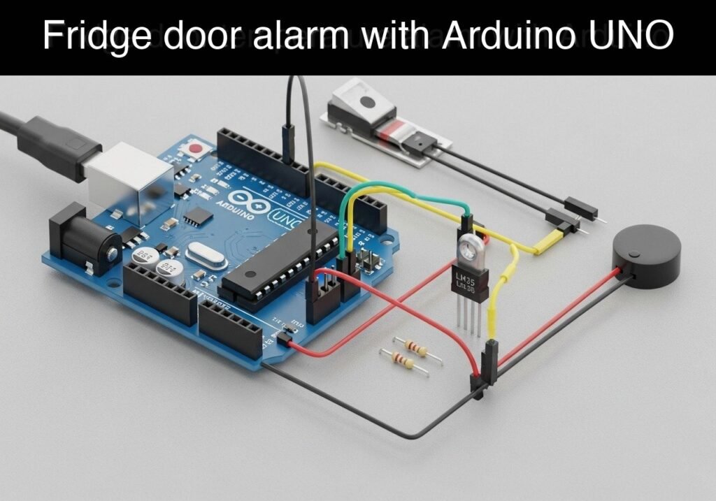
Objective and use case
What you’ll build: A prototype environmental monitor and alarm system that tracks refrigerator door status and internal temperature to prevent food spoilage and energy waste.
Why it matters / Use cases
- Commercial & Lab Storage: Prevents walk-in freezers from being left ajar and ensures temperature-sensitive chemical samples remain within strictly defined thermal thresholds.
- Domestic Energy Conservation: Eliminates energy waste and prevents compressor burnout caused by prolonged open doors in residential settings.
- Hardware State-Machine Education: Demonstrates practical non-blocking microcontroller code using
millis()to handle multiple independent sensors simultaneously without thread blocking.
Expected outcome
- The system continuously polls the LM35 temperature sensor every 2000ms (0.5 Hz) and streams data to the Serial Monitor for logging.
- A magnetic reed switch accurately detects open/closed door states with near-zero latency, triggering immediate state-machine transitions and temporal alarms.
Audience: Embedded Systems Developers, STEM Educators; Level: Intermediate
Architecture/flow: LM35 (Analog) & Reed Switch (Digital GPIO) → Microcontroller (Non-blocking State Machine) → Serial Monitor Logging & Alarm Triggers
Educational validation note
Before publication, this case passed the Prometeo automated validation gate with status PASS. The validator checked the code blocks, article structure, copy/paste-safe commands and consistency with the supported device catalog.
Published validation evidence
- Automatic result: PASS.
- Parsed structure: 3 sections, 1 tables and 2 code blocks detected before publication.
- Checked code: 1 Arduino/arduino-cli compile, 1 Bash/copy-paste checks.
- Supported catalog: the article text was checked against Prometeo’s validation-capable device profiles, and unsupported stacks block publication.
- Report findings: no blocking findings.
This validation confirms syntax and tool compatibility for the published material, but it does not replace physical testing on your exact hardware, wiring and runtime environment.
Educational safety note
This project is a low-voltage educational prototype, not a certified product. Before powering the setup, verify the wiring of your Arduino UNO R3, avoid shorting 5 V, GND or digital pins, disconnect power before changing connections, and use proper interface modules for relays, motors or external loads.
Conceptual block diagram
High-level view: what enters the system, what each block processes, and what comes out.
Functional architecture
Conceptual signal and responsibility flow between device blocks.

Validation path
Conceptual summary of the tools used to check the published material.

Validation Method and Accuracy
To validate the accuracy of the LM35 sensor readings, place a calibrated commercial digital thermometer in the exact same location as the LM35 inside the refrigerator.
* Expected Evidence: The serial output of the Arduino should report temperatures within ±0.5°C of the calibrated thermometer at standard refrigerator temperatures (2.0°C to 8.0°C) after allowing 10 minutes for the sensor casing to reach thermal equilibrium.
Prerequisites
Before beginning this tutorial, ensure you have the following tools and knowledge ready:
* A host computer running Linux, macOS, or Windows.
* Arduino CLI installed and added to your system’s PATH.
* A USB Type-A to Type-B cable to connect the Arduino UNO to your computer.
* Basic understanding of how to use a breadboard and jumper wires.
Materials
You will need the exact components listed below to build this prototype.
| Component | Exact Model / Specification | Quantity | Role in Prototype |
|---|---|---|---|
| Microcontroller | Arduino UNO R3 (ATmega328P) | 1 | The central processing unit evaluating sensor logic. |
| Temperature Sensor | LM35 (LM35DZ TO-92 package) | 1 | Precision analog sensor providing 10mV/°C linear output. |
| Magnetic Sensor | Standard Reed Switch (Normally Open) | 1 | Detects the presence of a magnet to determine door state. |
| Magnet | Small Neodymium or Ceramic Magnet | 1 | Mounted to the door to actuate the reed switch. |
| Audio Actuator | Piezo Buzzer (Passive or Active) | 1 | Emits audible alarm tones. |
| Wiring | Male-to-Male Jumper Wires | ~10 | Connects components on the breadboard to the Arduino. |
| Breadboard | Standard Half-Size Breadboard | 1 | Provides a solderless prototyping foundation. |
Note: We do not require an external pull-up resistor for the reed switch because we will utilize the ATmega328P’s internal pull-up resistor via software.
Setup/Connection
Follow these instructions carefully. Ensure your Arduino is disconnected from USB power while wiring.
1. LM35 Temperature Sensor Wiring
Hold the LM35 so the flat face with the printed text is facing you, and the three pins are pointing down.
* Left Pin (VCC): Connect to the 5V pin on the Arduino.
* Middle Pin (OUT): Connect to the A0 (Analog 0) pin on the Arduino.
* Right Pin (GND): Connect to a GND pin on the Arduino.
2. Reed Switch Wiring
A reed switch has two terminals and is non-polarized (orientation does not matter).
* Terminal 1: Connect to Digital Pin 2 on the Arduino.
* Terminal 2: Connect to a GND pin on the Arduino.
* Logic Note: We will configure Pin 2 as INPUT_PULLUP. When the magnet is near (door closed), the switch closes, connecting Pin 2 to GND (reading LOW). When the door opens, the switch opens, and the internal resistor pulls Pin 2 to 5V (reading HIGH).
3. Piezo Buzzer Wiring
If your piezo buzzer has a longer leg (positive) and a shorter leg (negative), follow this polarization.
* Positive Terminal (Longer leg / Red wire): Connect to Digital Pin 8 on the Arduino.
* Negative Terminal (Shorter leg / Black wire): Connect to a GND pin on the Arduino.
Arduino Sketch
Create a new directory named FridgeAlarm and create the following file inside it named FridgeAlarm.ino.
Public preview of the validated file. The complete source is shown to members and in PDF/Print.
/*
 * Fridge Door and Temperature Alarm
 * Architecture: Arduino UNO R3 (ATmega328P)
 * Sensors: Reed Switch (Pin 2), LM35 (Pin A0)
 * Actuator: Piezo Buzzer (Pin 8)
 */

// Hardware Pin Definitions
const int REED_PIN = 2;
const int BUZZER_PIN = 8;
const int LM35_PIN = A0;

// Configuration Thresholds
const float TEMP_THRESHOLD_C = 8.0;          // Alarm triggers if temperature exceeds 8.0 Celsius
const unsigned long DOOR_TIMEOUT_MS = 20000; // Alarm triggers if door is open for 20,000 ms (20 seconds)
const unsigned long TEMP_READ_INTERVAL = 2000; // Read temperature every 2,000 ms (2 seconds)

// State Tracking Variables
unsigned long doorOpenedAt = 0;
unsigned long lastTempRead = 0;

bool isDoorOpen = false;
bool tempAlarmActive = false;
bool doorAlarmActive = false;
float currentTemp = 0.0;

void setup() {
    // Initialize serial communication for data logging
    Serial.begin(115200);

    // Configure pins
    // INPUT_PULLUP applies an internal 20k-50k ohm resistor to 5V.
    pinMode(REED_PIN, INPUT_PULLUP);
    pinMode(BUZZER_PIN, OUTPUT);

    Serial.println("--- Fridge Monitor Initialized ---");
    Serial.print("Temp Threshold: ");
    Serial.print(TEMP_THRESHOLD_C);
    Serial.println(" C");
    Serial.print("Door Timeout: ");
    Serial.print(DOOR_TIMEOUT_MS / 1000);
    Serial.println(" seconds");
}

void loop() {
    // Capture current time once per loop iteration
    unsigned long currentMillis = millis();

    // ---------------------------------------------------------
    // 1. Evaluate Door State
    // ---------------------------------------------------------
    // Switch is closed (LOW) when magnet is present (door closed).
    // Switch is open (HIGH) when magnet is removed (door open).
    bool currentDoorState = (digitalRead(REED_PIN) == HIGH);

    // Detect state change: Door just opened
    if (currentDoorState && !isDoorOpen) {
        isDoorOpen = true;
        doorOpenedAt = currentMillis;
        Serial.println("[EVENT] Door Opened.");
    }
    // Detect state change: Door just closed
    else if (!currentDoorState && isDoorOpen) {
        isDoorOpen = false;
        doorAlarmActive = false;
        Serial.println("[EVENT] Door Closed.");
        noTone(BUZZER_PIN); // Silence any active door alarms
    }
// .../*
* Fridge Door and Temperature Alarm
* Architecture: Arduino UNO R3 (ATmega328P)
* Sensors: Reed Switch (Pin 2), LM35 (Pin A0)
* Actuator: Piezo Buzzer (Pin 8)
*/
// Hardware Pin Definitions
const int REED_PIN = 2;
const int BUZZER_PIN = 8;
const int LM35_PIN = A0;
// Configuration Thresholds
const float TEMP_THRESHOLD_C = 8.0; // Alarm triggers if temperature exceeds 8.0 Celsius
const unsigned long DOOR_TIMEOUT_MS = 20000; // Alarm triggers if door is open for 20,000 ms (20 seconds)
const unsigned long TEMP_READ_INTERVAL = 2000; // Read temperature every 2,000 ms (2 seconds)
// State Tracking Variables
unsigned long doorOpenedAt = 0;
unsigned long lastTempRead = 0;
bool isDoorOpen = false;
bool tempAlarmActive = false;
bool doorAlarmActive = false;
float currentTemp = 0.0;
void setup() {
// Initialize serial communication for data logging
Serial.begin(115200);
// Configure pins
// INPUT_PULLUP applies an internal 20k-50k ohm resistor to 5V.
pinMode(REED_PIN, INPUT_PULLUP);
pinMode(BUZZER_PIN, OUTPUT);
Serial.println("--- Fridge Monitor Initialized ---");
Serial.print("Temp Threshold: ");
Serial.print(TEMP_THRESHOLD_C);
Serial.println(" C");
Serial.print("Door Timeout: ");
Serial.print(DOOR_TIMEOUT_MS / 1000);
Serial.println(" seconds");
}
void loop() {
// Capture current time once per loop iteration
unsigned long currentMillis = millis();
// ---------------------------------------------------------
// 1. Evaluate Door State
// ---------------------------------------------------------
// Switch is closed (LOW) when magnet is present (door closed).
// Switch is open (HIGH) when magnet is removed (door open).
bool currentDoorState = (digitalRead(REED_PIN) == HIGH);
// Detect state change: Door just opened
if (currentDoorState && !isDoorOpen) {
isDoorOpen = true;
doorOpenedAt = currentMillis;
Serial.println("[EVENT] Door Opened.");
}
// Detect state change: Door just closed
else if (!currentDoorState && isDoorOpen) {
isDoorOpen = false;
doorAlarmActive = false;
Serial.println("[EVENT] Door Closed.");
noTone(BUZZER_PIN); // Silence any active door alarms
}
    // Check if door has been open longer than the timeout
    if (isDoorOpen && (currentMillis - doorOpenedAt >= DOOR_TIMEOUT_MS)) {
        if (!doorAlarmActive) {
            Serial.println("[ALARM] Door Open Timeout Exceeded!");
            doorAlarmActive = true;
        }
    }

    // ---------------------------------------------------------
    // 2. Evaluate Temperature
    // ---------------------------------------------------------
    if (currentMillis - lastTempRead >= TEMP_READ_INTERVAL) {
        lastTempRead = currentMillis;

        // Read 10-bit ADC value (0-1023)
        int adcValue = analogRead(LM35_PIN);

        // Convert ADC value to voltage (5V reference)
        // Note: 1024.0 is the correct divisor for a 10-bit AVR ADC
        float voltage = (adcValue / 1024.0) * 5.0;

        // LM35 outputs 10mV (0.01V) per degree Celsius
        currentTemp = voltage / 0.01;

        Serial.print("[DATA] Current Temp: ");
        Serial.print(currentTemp);
        Serial.println(" C");
// Trigger temperature alarm if threshold is exceeded
if (currentTemp > TEMP_THRESHOLD_C) {
if (!tempAlarmActive) {
Serial.println("[ALARM] Temperature Critical!");
tempAlarmActive = true;
}
} else {
if (tempAlarmActive) {
Serial.println("[RESOLVED] Temperature returned to normal.");
tempAlarmActive = false;
noTone(BUZZER_PIN); // Silence temp alarm
}
}
}
// ---------------------------------------------------------
// 3. Actuate Alarms (Non-blocking Buzzer Logic)
// ---------------------------------------------------------
// Priority 1: Door Alarm (Fast high-pitched beep)
if (doorAlarmActive) {
// Toggle tone every 250ms
if ((currentMillis / 250) % 2 == 0) {
tone(BUZZER_PIN, 1200); // 1200 Hz
} else {
noTone(BUZZER_PIN);
}
}
// Priority 2: Temperature Alarm (Slow lower-pitched beep)
// Only sound if the door alarm isn't already sounding
else if (tempAlarmActive && !doorAlarmActive) {
// Toggle tone every 1000ms
if ((currentMillis / 1000) % 2 == 0) {
tone(BUZZER_PIN, 600); // 600 Hz
} else {
noTone(BUZZER_PIN);
}
}
// No alarms active
else if (!doorAlarmActive && !tempAlarmActive) {
noTone(BUZZER_PIN);
}
}
Compilation and Upload Commands
Navigate to the directory just above your FridgeAlarm folder in your terminal. Ensure your Arduino UNO R3 is connected to your computer via USB. Identify your serial port (e.g., COM3 on Windows, /dev/ttyACM0 on Linux, or /dev/cu.usbmodem14101 on macOS) and run the following exact commands to prepare the environment, compile, and upload the sketch.
# Update the core index
arduino-cli core update-index

# Install the AVR core for Arduino UNO
arduino-cli core install arduino:avr

# Compile the sketch for the Arduino UNO R3
arduino-cli compile --fqbn arduino:avr:uno FridgeAlarm

# Upload the compiled code to the board (replace <PORT> with your actual port)
arduino-cli upload --fqbn arduino:avr:uno --port <PORT> FridgeAlarm
Find this product and/or books on this topic on Amazon
As an Amazon Associate, I earn from qualifying purchases. If you buy through this link, you help keep this project running.
Quick Quiz

Telecommunications Electronics Engineer and Computer Engineer (official degrees in Spain).

