
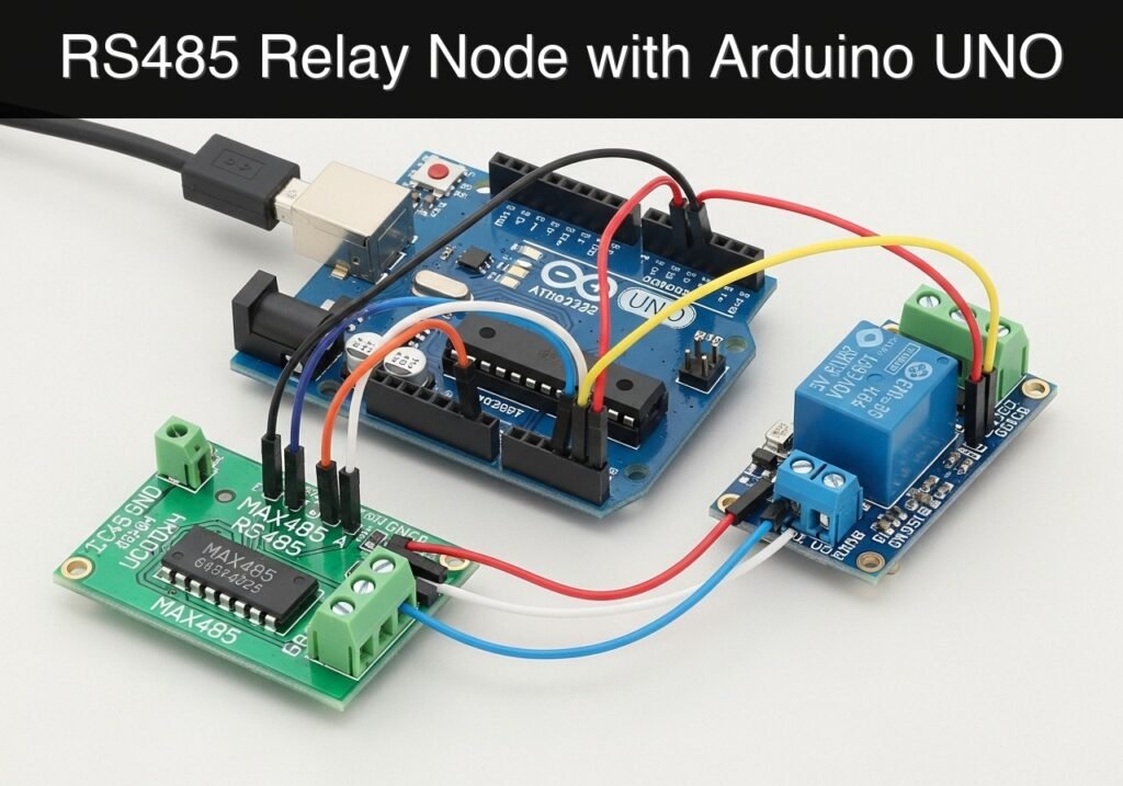
Objective and use case
What you’ll build: A robust, addressable remote relay node using an Arduino UNO that communicates over a long-distance RS485 bus to toggle a 5V relay based on targeted serial commands.
Why it matters / Use cases
- Agricultural Automation: Control irrigation valves or greenhouse ventilation fans hundreds of meters away where standard 3.3V UART, I2C, or SPI signals would degrade.
- Industrial Alert Systems: Trigger visual beacons across noisy factory floors. RS485 differential signaling provides high immunity to electromagnetic interference (EMI) from heavy machinery.
- Wired Home Automation: Create a deterministic, hardwired network of distributed switches that guarantees sub-10ms response times without relying on Wi-Fi coverage.
- Scalable Multi-drop Networks: Connect up to 32 addressable nodes on a single twisted pair of wires, ensuring each node only reacts to commands matching its specific ID.
Expected outcome
- The Arduino successfully interprets addressed serial commands and toggles the 5V relay with near-zero latency.
- Error-free communication is maintained over long wire runs (up to 1,200 meters at 9600 baud).
- The node correctly filters bus traffic, ignoring commands intended for other devices on the shared network.
Audience: Embedded developers and automation engineers; Level: Intermediate
Architecture/flow: Master Controller → RS485 Bus (Twisted Pair) → MAX485 Transceiver → Arduino UNO (UART) → GPIO → 5V Relay Module
Educational validation note
Before publication, this case passed the Prometeo automated validation gate with status PASS. The validator checked the code blocks, article structure, copy/paste-safe commands and consistency with the supported device catalog.
Published validation evidence
- Automatic result: PASS.
- Parsed structure: 3 sections, 3 tables and 2 code blocks detected before publication.
- Checked code: 1 Python/py_compile, 1 Arduino/arduino-cli compile.
- Supported catalog: the article text was checked against Prometeo’s validation-capable device profiles, and unsupported stacks block publication.
- Report findings: no blocking findings.
This validation confirms syntax and tool compatibility for the published material, but it does not replace physical testing on your exact hardware, wiring and runtime environment.
Educational safety note
This project is a low-voltage educational prototype, not a certified product. Before powering the setup, verify the wiring of your Arduino UNO R3, avoid shorting 5 V, GND or digital pins, disconnect power before changing connections, and use proper interface modules for relays, motors or external loads.
Conceptual block diagram
High-level view: what enters the system, what each block processes, and what comes out.
Functional architecture
Conceptual signal and responsibility flow between device blocks.

Validation path
Conceptual summary of the tools used to check the published material.

Prerequisites
- Familiarity with basic terminal operations and command-line interfaces.
- Understanding of standard UART (Serial) communication (Baud rate, TX/RX).
- Arduino CLI installed and added to your system’s PATH.
- Python 3.11 installed (for running the master validation script).
- The
pyseriallibrary installed in your Python environment (pip install pyserial).
Materials
- Microcontroller: Arduino UNO R3 (ATmega328P).
- Transceiver: MAX485 RS485 module (standard 8-pin breakout board with DI, DE, RE, RO pins).
- Actuator: 5 V relay module (opto-isolated, active-high or active-low).
- Master Interface: USB-to-RS485 adapter (to connect your PC to the RS485 bus for testing).
- Passive Components: 1x 120-ohm resistor (for bus termination, recommended for long cable runs).
- Cabling: Jumper wires, breadboard, and a twisted pair cable for the A/B RS485 lines.
Setup/Connection
RS485 is a half-duplex standard, meaning data travels in both directions, but only one direction at a time. The MAX485 chip uses Driver Enable (DE) and Receiver Enable (RE) pins to switch between transmitting and receiving. We will tie these two pins together and control them with a single digital pin on the Arduino.
We will use SoftwareSerial on pins 10 and 11 to communicate with the MAX485. This preserves the Arduino’s hardware serial port (pins 0 and 1) for USB debugging and uploading code without needing to disconnect the wiring.
Arduino to MAX485 Module Wiring
| MAX485 Pin | Arduino UNO Pin | Function / Description |
|---|---|---|
| VCC | 5V | Power supply for the transceiver. |
| GND | GND | Common ground reference. |
| RO (Receiver Out) | Digital Pin 10 | Connects to Arduino Software RX. |
| RE (Receiver Enable) | Digital Pin 2 | Active LOW. Tied to DE. |
| DE (Driver Enable) | Digital Pin 2 | Active HIGH. Tied to RE. |
| DI (Driver In) | Digital Pin 11 | Connects to Arduino Software TX. |
| A | USB-RS485 ‘A’ | Non-inverting RS485 bus line. |
| B | USB-RS485 ‘B’ | Inverting RS485 bus line. |
Note: Ensure the ground of the USB-to-RS485 adapter is connected to the Arduino’s ground to maintain a common reference voltage, especially for short-distance bench testing.
Arduino to 5V Relay Module Wiring
| Relay Module Pin | Arduino UNO Pin | Function / Description |
|---|---|---|
| VCC / DC+ | 5V | Power supply for the relay coil and optocoupler. |
| GND / DC- | GND | Common ground reference. |
| IN / Signal | Digital Pin 7 | Control signal to trigger the relay. |
Validated Code
The following sections contain the complete source code for both the Arduino node and the Python master script used to validate the bus.
Arduino Node Firmware
Create a directory named rs485_relay_node and save the following code as rs485_relay_node.ino inside it.
Public preview of the validated file. The complete source is shown to members and in PDF/Print.
/*
 * rs485_relay_node.ino
 *
 * Implements a half-duplex RS485 slave node.
 * Listens for "<NODE_ID>:<COMMAND>\n".
 * Valid commands: "ON", "OFF".
 */

#include <SoftwareSerial.h>

// Pin Definitions
#define RE_DE_PIN 2     // HIGH = Transmit, LOW = Receive
#define RELAY_PIN 7     // Relay control pin
#define RX_PIN 10       // SoftwareSerial RX
#define TX_PIN 11       // SoftwareSerial TX

// Node Configuration
const String NODE_ID = "N1";
const long BAUD_RATE = 9600;

// Initialize SoftwareSerial for RS485 communication
SoftwareSerial rs485(RX_PIN, TX_PIN);

void setup() {
  // Configure RS485 control pins
  pinMode(RE_DE_PIN, OUTPUT);
  digitalWrite(RE_DE_PIN, LOW); // Default to listen mode

  // Configure Relay pin
  pinMode(RELAY_PIN, OUTPUT);
  digitalWrite(RELAY_PIN, LOW); // Default relay state (adjust if active-low)

  // Initialize Serial ports
  Serial.begin(BAUD_RATE); // Hardware serial for debugging
  rs485.begin(BAUD_RATE);  // Software serial for RS485 bus

  Serial.println("System Boot: RS485 Relay Node");
  Serial.println("Node ID: " + NODE_ID);
  Serial.println("Listening for commands...");
}

void loop() {
  // Check if data is available on the RS485 bus
  if (rs485.available()) {
    // Read the incoming frame until a newline character
    String incomingMsg = rs485.readStringUntil('\n');
    incomingMsg.trim(); // Remove carriage returns or trailing spaces

    if (incomingMsg.length() > 0) {
      Serial.println("Bus traffic detected: " + incomingMsg);
      processCommand(incomingMsg);
    }
// .../*
* rs485_relay_node.ino
*
* Implements a half-duplex RS485 slave node.
* Listens for "<NODE_ID>:<COMMAND>\n".
* Valid commands: "ON", "OFF".
*/
#include <SoftwareSerial.h>
// Pin Definitions
#define RE_DE_PIN 2 // HIGH = Transmit, LOW = Receive
#define RELAY_PIN 7 // Relay control pin
#define RX_PIN 10 // SoftwareSerial RX
#define TX_PIN 11 // SoftwareSerial TX
// Node Configuration
const String NODE_ID = "N1";
const long BAUD_RATE = 9600;
// Initialize SoftwareSerial for RS485 communication
SoftwareSerial rs485(RX_PIN, TX_PIN);
void setup() {
// Configure RS485 control pins
pinMode(RE_DE_PIN, OUTPUT);
digitalWrite(RE_DE_PIN, LOW); // Default to listen mode
// Configure Relay pin
pinMode(RELAY_PIN, OUTPUT);
digitalWrite(RELAY_PIN, LOW); // Default relay state (adjust if active-low)
// Initialize Serial ports
Serial.begin(BAUD_RATE); // Hardware serial for debugging
rs485.begin(BAUD_RATE); // Software serial for RS485 bus
Serial.println("System Boot: RS485 Relay Node");
Serial.println("Node ID: " + NODE_ID);
Serial.println("Listening for commands...");
}
void loop() {
// Check if data is available on the RS485 bus
if (rs485.available()) {
// Read the incoming frame until a newline character
String incomingMsg = rs485.readStringUntil('\n');
incomingMsg.trim(); // Remove carriage returns or trailing spaces
if (incomingMsg.length() > 0) {
Serial.println("Bus traffic detected: " + incomingMsg);
processCommand(incomingMsg);
}
  }
}

void processCommand(String msg) {
  // Check if the message is addressed to this specific node
  if (msg.startsWith(NODE_ID + ":")) {
    // Extract the command portion after the colon
    int separatorIndex = msg.indexOf(':');
    String action = msg.substring(separatorIndex + 1);

    if (action == "ON") {
      digitalWrite(RELAY_PIN, HIGH);
      Serial.println("Action: Relay turned ON");
      sendAcknowledgment("ACK_ON");
    }
    else if (action == "OFF") {
      digitalWrite(RELAY_PIN, LOW);
      Serial.println("Action: Relay turned OFF");
      sendAcknowledgment("ACK_OFF");
    }
    else {
      Serial.println("Warning: Unknown command received.");
    }
  } else {
    // Message is for another node or malformed; ignore quietly
    Serial.println("Ignored: Addressed to another node.");
  }
}
void sendAcknowledgment(String ackMsg) {
// 1. Switch MAX485 to Transmit mode
digitalWrite(RE_DE_PIN, HIGH);
// 2. Allow a brief moment for the transceiver to stabilize
delay(5);
// 3. Transmit the acknowledgment frame
String fullAck = NODE_ID + ":" + ackMsg;
rs485.println(fullAck);
// 4. Wait for the serial transmission buffer to empty completely
// This is critical. If we pull RE_DE low too early, the transmission is cut off.
rs485.flush();
// 5. Allow the final bit to hit the wire before switching states
delay(5);
// 6. Switch MAX485 back to Receive mode
digitalWrite(RE_DE_PIN, LOW);
Serial.println("Transmitted: " + fullAck);
}
Python Master Test Script
Save the following code as master_controller.py on your PC. This script acts as the central controller, generating RS485 traffic to test the Arduino node.
Public preview of the validated file. The complete source is shown to members and in PDF/Print.
#!/usr/bin/env python3
"""
master_controller.py
Validates the Arduino RS485 Relay Node by sending specific string commands
over a USB-to-RS485 adapter and waiting for acknowledgments.
"""

import serial
import time
import sys

# Windows: 'COM3', Linux: '/dev/ttyUSB0', macOS: '/dev/cu.usbserial-...'
PORT = '/dev/ttyUSB0'
BAUD = 9600
TIMEOUT = 2.0

def send_and_wait(ser, node_id, command):
    """Sends a formatted command and waits for an acknowledgment."""
    frame = f"{node_id}:{command}\n"
    print(f"\n[Master] Sending : {frame.strip()}")

    # Send the byte-encoded string over the serial port
    ser.write(frame.encode('ascii'))

    # Wait for the node to process and respond
    time.sleep(0.1)

    # Read the response if available
    response_received = False
    start_time = time.time()

    while (time.time() - start_time) < TIMEOUT:
        if ser.in_waiting > 0:
            response = ser.readline().decode('ascii', errors='ignore').strip()
            print(f"[Master] Received: {response}")
            response_received = True
            break
        time.sleep(0.05)

    if not response_received:
        print("[Master] Error: No response received (Timeout).")
# ...#!/usr/bin/env python3
"""
master_controller.py
Validates the Arduino RS485 Relay Node by sending specific string commands
over a USB-to-RS485 adapter and waiting for acknowledgments.
"""
import serial
import time
import sys
# Windows: 'COM3', Linux: '/dev/ttyUSB0', macOS: '/dev/cu.usbserial-...'
PORT = '/dev/ttyUSB0'
BAUD = 9600
TIMEOUT = 2.0
def send_and_wait(ser, node_id, command):
"""Sends a formatted command and waits for an acknowledgment."""
frame = f"{node_id}:{command}\n"
print(f"\n[Master] Sending : {frame.strip()}")
# Send the byte-encoded string over the serial port
ser.write(frame.encode('ascii'))
# Wait for the node to process and respond
time.sleep(0.1)
# Read the response if available
response_received = False
start_time = time.time()
while (time.time() - start_time) < TIMEOUT:
if ser.in_waiting > 0:
response = ser.readline().decode('ascii', errors='ignore').strip()
print(f"[Master] Received: {response}")
response_received = True
break
time.sleep(0.05)
if not response_received:
print("[Master] Error: No response received (Timeout).")
def main():
    try:
        print(f"Opening port {PORT} at {BAUD} baud...")
        with serial.Serial(PORT, BAUD, timeout=TIMEOUT) as ser:
            time.sleep(2) # Allow port initialization

            print("--- Starting Validation Sequence ---")

            # Test 1: Turn Relay ON
            send_and_wait(ser, "N1", "ON")
            time.sleep(2)

            # Test 2: Turn Relay OFF
            send_and_wait(ser, "N1", "OFF")
            time.sleep(2)

            # Test 3: Test Address Filtering (Should be ignored by N1)
            send_and_wait(ser, "N2", "ON")

            print("\n--- Validation Sequence Complete ---")

    except serial.SerialException as e:
        print(f"Serial Port Error: {e}")
        sys.exit(1)
    except KeyboardInterrupt:
        print("\nProcess aborted by user.")
        sys.exit(0)
if __name__ == '__main__':
main()
Build/Flash/Run commands
Use the Arduino CLI to compile and flash the firmware to your Arduino UNO R3. Ensure your terminal is open in the directory containing rs485_relay_node.
| Task | Command |
|---|---|
| Update core index | arduino-cli core update-index |
| Install AVR core | arduino-cli core install arduino:avr |
| Compile sketch | arduino-cli compile --fqbn arduino:avr:uno rs485_relay_node |
| Upload to board | arduino-cli upload --fqbn arduino:avr:uno --port <PORT> rs485_relay_node |
Workflow steps:
1. Connect the Arduino UNO to your PC via USB.
2. Identify the port (e.g., COM3 on Windows or /dev/ttyACM0 on Linux) using arduino-cli board list.
3. Run the compilation command to ensure there are no syntax errors.
4. Run the upload command, replacing <PORT> with your specific port identifier.
5. Open a serial monitor (`arduino-
Find this product and/or books on this topic on Amazon
As an Amazon Associate, I earn from qualifying purchases. If you buy through this link, you help keep this project running.
Quick Quiz

Telecommunications Electronics Engineer and Computer Engineer (official degrees in Spain).

