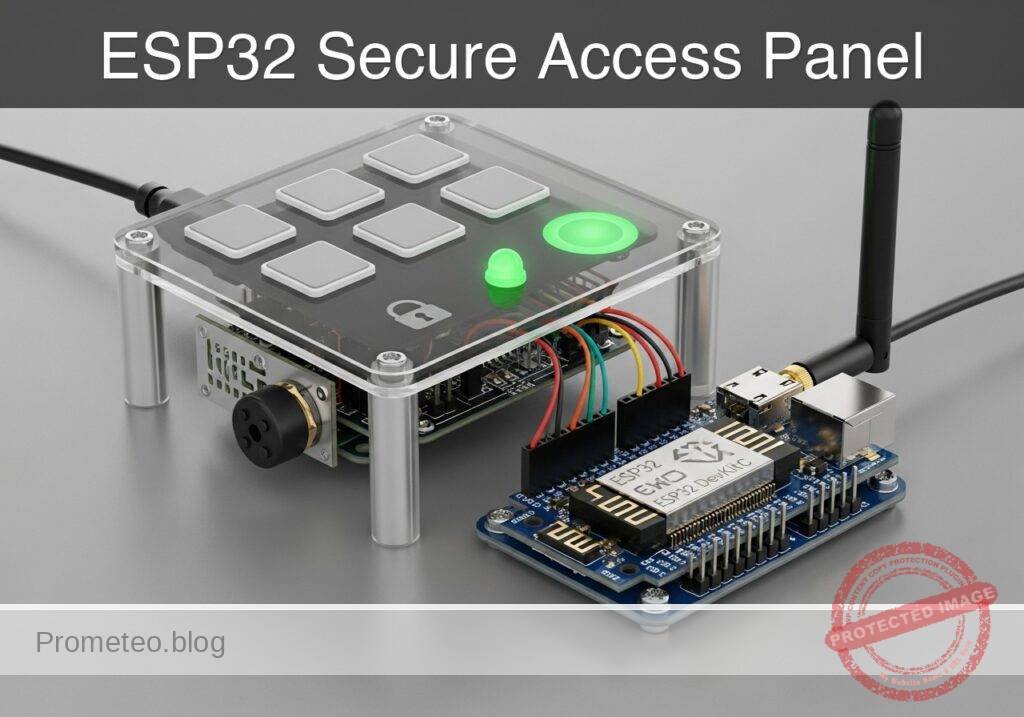
Objective and use case
What you’ll build: A functional prototype of a secure access panel utilizing the ESP32’s built-in capacitive touch sensing, visual LED indicators, and acoustic buzzer feedback.
Why it matters / Use cases
- Wear-free interfaces: Eliminates mechanical degradation, making it ideal for high-traffic access panels, cleanrooms, or outdoor keypads exposed to the elements.
- Secure building automation: Demonstrates the fundamental logic of sequence validation and state management required in frontline commercial security systems.
- Integrated user feedback: Combines visual (LED) and acoustic (buzzer) signals for a robust HMI, ensuring users know input was registered with sub-50ms response latency.
- Non-blocking state machines: Manages asynchronous human input without halting the microcontroller, maintaining constant system responsiveness.
Expected outcome
- Reliable touch detection and software debouncing utilizing the ESP32’s internal capacitive hardware.
- A non-blocking state machine capable of processing sequential inputs and rejecting invalid codes instantly.
- Synchronized, low-latency GPIO actuation driving LED and buzzer feedback based on access state.
Audience: Embedded Systems Engineers, IoT Developers; Level: Intermediate
Architecture/flow: ESP32 Capacitive Touch Pins → Software Debounce Filter → Non-blocking Sequence Validator → GPIO Actuation (LED/Buzzer)
Educational validation note
Before publication, this case passed the Prometeo automated validation gate with status PASS. For this ESP32 DevKitC profile, the project was checked as a PlatformIO project: the validator extracted platformio.ini and src/main.cpp, created a temporary project and ran pio run against platform = espressif32, board = esp32dev and framework = arduino. It also checked article structure, copy/paste-safe ASCII command options, and unsupported stacks such as direct ESP-IDF or non-scoped ESP32 boards.
Published validation evidence
- Automatic result: PASS.
- Parsed structure: 3 sections, 2 tables and 2 code blocks detected before publication.
- Checked code: 1 PlatformIO config + 1 ESP32 source/pio run.
- Supported catalog: the article text was checked against Prometeo’s validation-capable device profiles, and unsupported stacks block publication.
- Report findings: no blocking findings.
This validation confirms syntax and tool compatibility for the published code, but it does not replace physical testing on your exact ESP32 DevKitC board, wiring, power supply and local WiFi environment.
Educational safety note
This project is an educational prototype, not a certified product. Before powering the setup, verify the pinout of your exact ULX3S board revision, keep FPGA I/O signals at 3.3 V, never connect 5 V directly to I/O pins, disconnect power before changing wiring, and use suitable external supplies for loads, motors or servos while sharing ground only when the wiring requires it.
Conceptual block diagram
High-level view: what enters the system, what each block processes, and what comes out.
Functional architecture
Conceptual signal and responsibility flow between device blocks.

Validation path
Conceptual summary of the tools used to check the published material.

Prerequisites
To successfully complete this tutorial, you will need:
* Basic understanding of C++ programming (variables, arrays, conditional logic, and functions).
* Visual Studio Code installed with the PlatformIO IDE extension.
* Familiarity with breadboard prototyping and basic electronic components.
* A micro-USB or USB-C cable (depending on your specific ESP32 DevKitC variant) capable of both power and data transfer.
Materials
You must use the exact components listed below to ensure the provided code and wiring instructions work without modification:
* Microcontroller: ESP32 DevKitC (Standard 38-pin or 30-pin version).
* Input: Capacitive touch pads. (You can use dedicated commercial touch pad modules, or easily create your own using copper tape, aluminum foil, or metallic coins soldered to jumper wires).
* Output (Visual): 1x Standard 5mm Status LED (e.g., Red or Green) and 1x 220Ω to 330Ω current-limiting resistor.
* Output (Audio): 1x Piezo buzzer (passive type preferred for variable tones, though an active buzzer will work for simple beeps).
* Prototyping: 1x Solderless breadboard and assorted male-to-male jumper wires.
Hardware Setup Note: Ensure your computer has the appropriate USB-to-UART bridge drivers installed (typically CP210x or CH34x, depending on the manufacturer of your ESP32 DevKitC) so that PlatformIO can communicate with the board.
Setup/Connection
The ESP32 features dedicated internal touch-sensing hardware on several GPIO pins. These pins measure the capacitance of the connected circuit. When a human finger touches the pad, the capacitance changes, which the ESP32 detects as a drop in the raw analog value.
Because the ESP32 handles the capacitance measurement internally, you do not need external pull-up or pull-down resistors for the touch pads. Connect the components according to the table below.
Pin Mapping Table
| Component | ESP32 DevKitC Pin | Details & Connections |
|---|---|---|
| Touch Pad 1 (Key 1) | GPIO 4 (Touch 0) | Connect directly to the metallic pad/coin. |
| Touch Pad 2 (Key 2) | GPIO 2 (Touch 2) | Connect directly to the metallic pad/coin. |
| Touch Pad 3 (Key 3) | GPIO 15 (Touch 3) | Connect directly to the metallic pad/coin. |
| Status LED Anode (+) | GPIO 21 | Connect via a 220Ω resistor to GPIO 21. |
| Status LED Cathode (-) | GND | Connect directly to the ESP32 Ground (GND) pin. |
| Piezo Buzzer (+) | GPIO 22 | Connect to GPIO 22. |
| Piezo Buzzer (-) | GND | Connect to the ESP32 Ground (GND) pin. |
Constructing the Touch Pads: If you do not have commercial touch pads, cut three identical squares of copper tape or use three identical coins. Solder or firmly tape a jumper wire to each. Space them at least 2 centimeters apart on your desk or breadboard to prevent cross-capacitance (where touching one pad accidentally triggers an adjacent one).
Validated Code
The following files constitute the complete, compilable project. The project is managed via PlatformIO.
platformio.ini
Create or overwrite the platformio.ini file in the root of your project directory with the following configuration. This ensures the correct board and framework are targeted.
[env:esp32dev]
platform = espressif32
board = esp32dev
framework = arduino
monitor_speed = 115200
src/main.cpp
Create or overwrite the main.cpp file in your src directory with the following code. The logic implements a non-blocking state machine, handles touch debouncing, and manages the access validation sequence.
Public preview of the validated file. The complete source is shown to members and in PDF/Print.
#include <Arduino.h>

// --------------------------------------------------------
// Pin Definitions
// --------------------------------------------------------
const int TOUCH_PAD_1 = 4;  // GPIO 4  (Touch 0)
const int TOUCH_PAD_2 = 2;  // GPIO 2  (Touch 2)
const int TOUCH_PAD_3 = 15; // GPIO 15 (Touch 3)
const int LED_PIN     = 21; // Status LED
const int BUZZER_PIN  = 22; // Piezo Buzzer

// --------------------------------------------------------
// System Configuration & Thresholds
// --------------------------------------------------------
// A typical untouched ESP32 pin reads ~50-80.
// A touched pin drops below 20. Adjust this if your pads differ.
const int TOUCH_THRESHOLD = 30;

// Access Control Sequence Configuration
const int SEQUENCE_LENGTH = 4;
const int SECRET_PIN[SEQUENCE_LENGTH] = {1, 2, 3, 2}; // The correct access code
int inputSequence[SEQUENCE_LENGTH];
int inputIndex = 0;

// State Machine Variables
enum SystemState { LOCKED, INPUTTING, UNLOCKED };
SystemState currentState = LOCKED;

unsigned long unlockTimestamp = 0;
const unsigned long UNLOCK_DURATION = 5000; // Keep unlocked for 5 seconds

// Debouncing Variables
bool pad1_wasTouched = false;
bool pad2_wasTouched = false;
bool pad3_wasTouched = false;

// --------------------------------------------------------
// Function Prototypes
// --------------------------------------------------------
void processTouch();
void handleKeyPress(int keyNumber);
void evaluateSequence();
void triggerSuccess();
void triggerFailure();
void lockSystem();
void playTone(int frequency, int duration);

// --------------------------------------------------------
// Setup
// --------------------------------------------------------
void setup() {
    Serial.begin(115200);
    while (!Serial) { delay(10); } // Wait for serial connection

    Serial.println("\n--- Capacitive Touch Access Panel Initialized ---");

    pinMode(LED_PIN, OUTPUT);
    pinMode(BUZZER_PIN, OUTPUT);

    lockSystem(); // Ensure system starts in locked state
}

// --------------------------------------------------------
// Main Loop
// --------------------------------------------------------
void loop() {
    // Handle state timeouts (Auto-lock)
    if (currentState == UNLOCKED) {
        if (millis() - unlockTimestamp >= UNLOCK_DURATION) {
            Serial.println("Auto-locking system due to timeout.");
            lockSystem();
        }
    } else {
        // Only process touch inputs if the system is not currently unlocked
        processTouch();
    }

    // Small delay to yield to the underlying RTOS
    delay(10);
}

// --------------------------------------------------------
// Touch Processing & Debouncing
// --------------------------------------------------------
void processTouch() {
    // Read raw capacitance values
    int val1 = touchRead(TOUCH_PAD_1);
    int val2 = touchRead(TOUCH_PAD_2);
    int val3 = touchRead(TOUCH_PAD_3);

    // Evaluate Pad 1
    bool pad1_isTouched = (val1 < TOUCH_THRESHOLD);
    if (pad1_isTouched && !pad1_wasTouched) {
        handleKeyPress(1);
    }
    pad1_wasTouched = pad1_isTouched;

    // Evaluate Pad 2
    bool pad2_isTouched = (val2 < TOUCH_THRESHOLD);
    if (pad2_isTouched && !pad2_wasTouched) {
        handleKeyPress(2);
    }
// ...#include <Arduino.h>
// --------------------------------------------------------
// Pin Definitions
// --------------------------------------------------------
const int TOUCH_PAD_1 = 4; // GPIO 4 (Touch 0)
const int TOUCH_PAD_2 = 2; // GPIO 2 (Touch 2)
const int TOUCH_PAD_3 = 15; // GPIO 15 (Touch 3)
const int LED_PIN = 21; // Status LED
const int BUZZER_PIN = 22; // Piezo Buzzer
// --------------------------------------------------------
// System Configuration & Thresholds
// --------------------------------------------------------
// A typical untouched ESP32 pin reads ~50-80.
// A touched pin drops below 20. Adjust this if your pads differ.
const int TOUCH_THRESHOLD = 30;
// Access Control Sequence Configuration
const int SEQUENCE_LENGTH = 4;
const int SECRET_PIN[SEQUENCE_LENGTH] = {1, 2, 3, 2}; // The correct access code
int inputSequence[SEQUENCE_LENGTH];
int inputIndex = 0;
// State Machine Variables
enum SystemState { LOCKED, INPUTTING, UNLOCKED };
SystemState currentState = LOCKED;
unsigned long unlockTimestamp = 0;
const unsigned long UNLOCK_DURATION = 5000; // Keep unlocked for 5 seconds
// Debouncing Variables
bool pad1_wasTouched = false;
bool pad2_wasTouched = false;
bool pad3_wasTouched = false;
// --------------------------------------------------------
// Function Prototypes
// --------------------------------------------------------
void processTouch();
void handleKeyPress(int keyNumber);
void evaluateSequence();
void triggerSuccess();
void triggerFailure();
void lockSystem();
void playTone(int frequency, int duration);
// --------------------------------------------------------
// Setup
// --------------------------------------------------------
void setup() {
Serial.begin(115200);
while (!Serial) { delay(10); } // Wait for serial connection
Serial.println("\n--- Capacitive Touch Access Panel Initialized ---");
pinMode(LED_PIN, OUTPUT);
pinMode(BUZZER_PIN, OUTPUT);
lockSystem(); // Ensure system starts in locked state
}
// --------------------------------------------------------
// Main Loop
// --------------------------------------------------------
void loop() {
// Handle state timeouts (Auto-lock)
if (currentState == UNLOCKED) {
if (millis() - unlockTimestamp >= UNLOCK_DURATION) {
Serial.println("Auto-locking system due to timeout.");
lockSystem();
}
} else {
// Only process touch inputs if the system is not currently unlocked
processTouch();
}
// Small delay to yield to the underlying RTOS
delay(10);
}
// --------------------------------------------------------
// Touch Processing & Debouncing
// --------------------------------------------------------
void processTouch() {
// Read raw capacitance values
int val1 = touchRead(TOUCH_PAD_1);
int val2 = touchRead(TOUCH_PAD_2);
int val3 = touchRead(TOUCH_PAD_3);
// Evaluate Pad 1
bool pad1_isTouched = (val1 < TOUCH_THRESHOLD);
if (pad1_isTouched && !pad1_wasTouched) {
handleKeyPress(1);
}
pad1_wasTouched = pad1_isTouched;
// Evaluate Pad 2
bool pad2_isTouched = (val2 < TOUCH_THRESHOLD);
if (pad2_isTouched && !pad2_wasTouched) {
handleKeyPress(2);
}
    pad2_wasTouched = pad2_isTouched;

    // Evaluate Pad 3
    bool pad3_isTouched = (val3 < TOUCH_THRESHOLD);
    if (pad3_isTouched && !pad3_wasTouched) {
        handleKeyPress(3);
    }
    pad3_wasTouched = pad3_isTouched;
}

// --------------------------------------------------------
// Logic Handling
// --------------------------------------------------------
void handleKeyPress(int keyNumber) {
    // Provide immediate acoustic feedback
    playTone(1000, 100);

    Serial.print("Key Pressed: ");
    Serial.println(keyNumber);

    // Update state
    currentState = INPUTTING;

    // Store the input
    inputSequence[inputIndex] = keyNumber;
    inputIndex++;

    // Check if we have collected enough inputs
if (inputIndex >= SEQUENCE_LENGTH) {
evaluateSequence();
}
}
void evaluateSequence() {
Serial.println("Evaluating entered sequence...");
bool isMatch = true;
for (int i = 0; i < SEQUENCE_LENGTH; i++) {
if (inputSequence[i] != SECRET_PIN[i]) {
isMatch = false;
break;
}
}
if (isMatch) {
triggerSuccess();
} else {
triggerFailure();
}
// Reset input index for the next attempt
inputIndex = 0;
}
// --------------------------------------------------------
// Output & Feedback Generators
// --------------------------------------------------------
void triggerSuccess() {
Serial.println("ACCESS GRANTED.");
currentState = UNLOCKED;
unlockTimestamp = millis();
// Visual indicator: LED ON
digitalWrite(LED_PIN, HIGH);
// Acoustic indicator: Success Melody
playTone(1200, 150);
delay(50);
playTone(1500, 150);
delay(50);
playTone(2000, 300);
}
void triggerFailure() {
Serial.println("ACCESS DENIED. Incorrect PIN.");
// Acoustic indicator: Error Tone
playTone(300, 400);
delay(100);
playTone(300, 400);
// Return to locked state immediately
lockSystem();
}
void lockSystem() {
currentState = LOCKED;
inputIndex = 0; // Clear any partial inputs
digitalWrite(LED_PIN, LOW); // LED OFF indicates locked
Serial.println("System LOCKED. Ready for input.");
}
// Helper function for the buzzer
void playTone(int frequency, int duration) {
tone(BUZZER_PIN, frequency, duration);
// The tone function in Arduino is non-blocking, but for this HMI
// we want the beep to complete before proceeding in feedback sequences.
delay(duration);
}
Build/Flash/Run commands
To compile, upload, and monitor the project, open the terminal in Visual Studio Code (Terminal -> New Terminal) and ensure you are in the root directory of your project (where platformio.ini is located).
Use the following commands:
| Command | Action |
|---|---|
pio run | Compiles the C++ source code and checks for syntax/linking errors. |
pio run --target upload | Compiles and flashes the compiled firmware to the ESP32 DevKitC. |
pio device monitor | Opens the serial monitor to view real-time logs from the ESP32. |
Numbered Workflow:
1. Connect the ESP32 DevKitC to your computer via USB.
2. Execute pio run to verify the code compiles cleanly.
3. Execute pio run --target upload to flash the board. (Note: On some ESP32 DevKitC models, you may need to hold down the “BOOT” button on the board when the terminal displays “Connecting…” to allow the flash process to begin).
4. Execute pio device monitor to interact with the device and view the serial output.
Step-by-step Validation
Perform the following physical checks while observing the serial monitor to validate the prototype’s functionality.
- Checkpoint 1: Baseline Initialization
- Action: Reset the ESP32 (press the EN button) while observing the serial monitor.
- Expected Observation: The serial monitor prints “— Capacitive Touch Access Panel Initialized —” followed by “System LOCKED. Ready for input.” The status LED should remain off.
- Pass Condition: Clean boot sequence with no boot loops or crashes.
- Checkpoint 2: Single Touch Detection & Debounce
- Action: Firmly tap Touch Pad 1 once and release it immediately.
- Expected Observation: The buzzer emits a short 100ms beep. The serial monitor logs “Key Pressed: 1”.
- Pass Condition: Only a single press is registered per physical tap. If multiple presses register, the
TOUCH_THRESHOLDmay need adjustment.
- Checkpoint 3: Incorrect Sequence Rejection
- Action: Tap the pads in an incorrect sequence (e.g., Pad 1, Pad 1, Pad 1, Pad 1).
- Expected Observation: Upon the 4th tap, the serial monitor logs “Evaluating entered sequence…” followed by “ACCESS DENIED. Incorrect PIN.” The buzzer plays two low, long error tones. The LED remains off.
- Pass Condition: The system correctly identifies a mismatch and returns to the “System LOCKED” state.
- Checkpoint 4: Correct Sequence Authorization
- Action: Tap the pads in the correct sequence defined in the code (Pad 1, Pad 2, Pad 3, Pad 2).
- Expected Observation: The serial monitor logs “ACCESS GR
Find this product and/or books on this topic on Amazon
As an Amazon Associate, I earn from qualifying purchases. If you buy through this link, you help keep this project running.
Quick Quiz

Telecommunications Electronics Engineer and Computer Engineer (official degrees in Spain).