
Building a Dust Collector Current Monitor with ESP32
Objective and use case
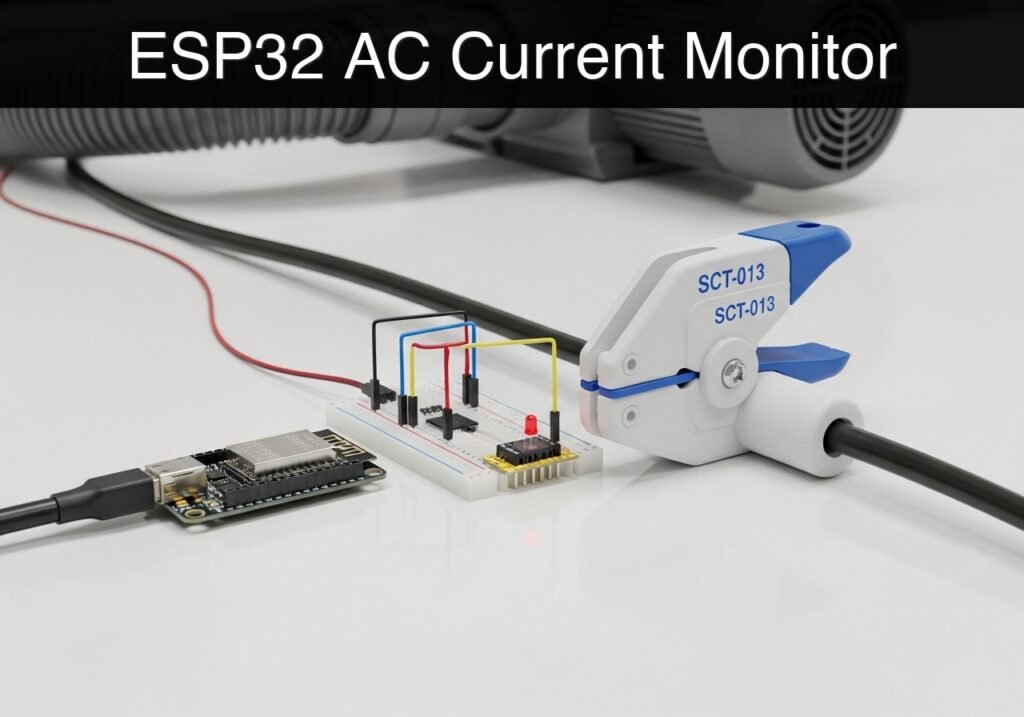
What you’ll build: A non-invasive dust collector current monitor that logs the AC power draw of your workshop’s dust collection system to establish a baseline electrical usage profile and detect operational anomalies.
Why it matters / Use cases
- Equipment Monitoring: Detect a stalled impeller or failing motor bearings by identifying abnormal operating current spikes (e.g., a sudden surge far above the baseline).
- Filter/Clog Detection: Identify gradual decreases or unexpected drops in baseline current draw that indicate restricted airflow or a clogged dust collector filter (since centrifugal fans draw less current when airflow is restricted).
- Energy Profiling: Log continuous electrical usage over time to accurately calculate the energy costs of running the dust collector during workshop hours.
Expected outcome
- The ESP32 will sample the analog alternating current (AC) waveform at high speed to calculate the Root Mean Square (RMS) current mathematically, without relying on external libraries.
- Serial monitor output will display real-time current draw in Amperes for the dust collector.
- The system will actively filter out baseline electrical noise to prevent false positive readings during idle machine states.
Audience: Basic electronics and programming students looking to interface analog sensors and implement signal processing math; Level: Intermediate
Architecture/flow: Non-invasive CT Current Sensor → ESP32 ADC → Custom RMS Signal Processing → Serial Monitor Output
Educational validation note
Before publication, this case passed the Prometeo automated validation gate with status PASS. For this ESP32 DevKitC profile, the project was checked as a PlatformIO project: the validator extracted platformio.ini and src/main.cpp, created a temporary project and ran pio run against platform = espressif32, board = esp32dev and framework = arduino. It also checked article structure, copy/paste-safe ASCII command options, and unsupported stacks such as direct ESP-IDF or non-scoped ESP32 boards.
Published validation evidence
- Automatic result: PASS.
- Parsed structure: 3 sections, 3 tables and 2 code blocks detected before publication.
- Checked code: 1 PlatformIO config + 1 ESP32 source/pio run.
- Supported catalog: the article text was checked against Prometeo’s validation-capable device profiles, and unsupported stacks block publication.
- Report findings: no blocking findings.
This validation confirms syntax and tool compatibility for the published code, but it does not replace physical testing on your exact ESP32 DevKitC board, wiring, power supply and local WiFi environment.
Educational safety note
WARNING: HIGH VOLTAGE. This tutorial involves monitoring AC mains appliances. The SCT-013 is a non-invasive current transformer. You must never cut, strip, or expose bare AC mains wires to use this sensor. The clamp must only be placed over wires with intact, factory-rated insulation.
Additionally:
* Never attempt to wire the SCT-013 directly to the ESP32 without the 33Ω burden resistor in place. Without a burden resistor, a disconnected current transformer can generate dangerously high voltages on its output pins when clamped over a live wire.
* This prototype is an educational tool. Do not use it as a primary safety disconnect or industrial monitoring mechanism.
* Always ensure your low-voltage microcontroller circuits are physically isolated and safely distanced from high-voltage AC lines.
Conceptual block diagram
High-level view: what enters the system, what each block processes, and what comes out.
Functional architecture
Conceptual flow: moisture detection, local decision and user alert.

Validation path
Conceptual summary of the tools used to check the published ESP32 project.

Prerequisites
To successfully complete this tutorial, you need:
* A computer with Visual Studio Code and the PlatformIO IDE extension installed.
* Basic familiarity with breadboarding and jumper wire connections.
* Understanding of the difference between AC and DC signals (specifically, that ESP32 analog pins can only read positive DC voltages between 0V and 3.3V).
* A test appliance (like a desk lamp or a small fan) plugged into an AC splitter where the live and neutral wires are physically separated, before moving to the actual dust collector.
Hardware Setup Note: If your computer does not automatically recognize the ESP32 DevKitC, you may need to install the CP210x or CH34x USB-to-UART drivers specific to your board’s serial chip.
Materials
You will need the following exact components for this build:
* ESP32 DevKitC (Standard 38-pin or 30-pin development board).
* SCT-013 current transformer module (Specifically the SCT-013-000, which is a 100A/50mA current-type transformer).
* Burden resistor: 1x 33Ω resistor (1/4 Watt is sufficient).
* DC Bias components: 2x 10kΩ resistors and 1x 10µF electrolytic capacitor (required to shift the AC wave into the ESP32’s readable DC range).
* Audio Jack Breakout: A 3.5mm female TRS breakout board (to easily connect the SCT-013 plug to the breadboard).
* Breadboard and jumper wires.
Setup/Connection
The SCT-013-000 outputs an AC current proportional to the current flowing through the clamped wire. Because the ESP32’s Analog-to-Digital Converter (ADC) can only measure positive DC voltages up to 3.3V, we must do two things:
1. Convert the sensor’s current output into a voltage using a burden resistor.
2. Shift the AC waveform (which goes positive and negative) entirely into the positive range using a DC bias network (a voltage divider).
DC Bias and Sensor Wiring
- Connect the two 10kΩ resistors in series between the ESP32
3V3pin andGND. The junction between these two resistors is your “midpoint,” resting at exactly 1.65V. - Connect the positive leg (anode) of the 10µF capacitor to this 1.65V midpoint, and the negative leg (cathode) to
GND. This smooths out noise from the power supply. - Connect the Sleeve (Ground/Shield) of the 3.5mm audio jack breakout to the 1.65V midpoint.
- Connect the Tip of the 3.5mm audio jack breakout to ESP32 Pin
34(an input-only ADC pin). - Place the 33Ω burden resistor directly across the Tip and Sleeve connections of the audio jack breakout.
Pin Mapping Table
| ESP32 DevKitC Pin | Component Connection | Function |
|---|---|---|
3V3 | 10kΩ Resistor #1 (Top) | Provides 3.3V power for the DC bias divider. |
GND | 10kΩ Resistor #2 (Bottom), Capacitor (-) | Common ground reference. |
34 (ADC1_CH6) | Audio Jack Tip, Burden Resistor Side A | Reads the fluctuating AC voltage. |
| N/A (Midpoint) | Audio Jack Sleeve, Burden Resistor Side B | Provides 1.65V virtual ground offset. |
Clamping the Sensor
To measure current, the SCT-013 must be clamped around only one wire (either the Live/Hot wire OR the Neutral wire) of the dust collector’s power cable. If you clamp it around a standard power cord containing both wires, the magnetic fields of the outgoing and returning currents will cancel each other out, and the sensor will read 0 Amperes.
Full Code
The following code calculates the RMS current mathematically by sampling the ADC rapidly, calculating the variance of the waveform, and deriving the true AC component. This avoids external library dependencies and guarantees compilation. Create a new PlatformIO project for the ESP32 DevKitC and replace the default files with the code below.
platformio.ini
[env:esp32dev]
platform = espressif32
board = esp32dev
framework = arduino
monitor_speed = 115200
src/main.cpp
Public preview of the validated file. The complete source is shown to members and in PDF/Print.
#include <Arduino.h>

// ---------------------------------------------------------
// Configuration & Constants
// ---------------------------------------------------------
const int ADC_PIN = 34;               // Analog input pin connected to the SCT-013
const float V_REF = 3.3;              // ESP32 ADC reference voltage
const int ADC_RESOLUTION = 4095;      // 12-bit ADC maximum value
const float BURDEN_RESISTOR = 33.0;   // Burden resistor value in Ohms
const float CT_TURNS_RATIO = 2000.0;  // For SCT-013-000: 100A / 0.050A = 2000

void setup() {
    Serial.begin(115200);
    while (!Serial) {
        ; // Wait for serial port to connect
    }

    Serial.println("Dust Collector Current Monitor Initializing...");

    // Configure the ADC pin
    analogReadResolution(12);
    pinMode(ADC_PIN, INPUT);

    Serial.println("Initialization Complete. Monitoring Current...");
}

void loop() {
    unsigned long startMillis = millis();
    double sum = 0;
    double sumSquared = 0;
    int samples = 0;

    // Sample the waveform for 200ms (captures 10-12 full AC cycles)
    while (millis() - startMillis < 200) {
        int raw = analogRead(ADC_PIN);
        sum += raw;
        sumSquared += ((double)raw * raw);
        samples++;

        // Small delay to prevent FreeRTOS watchdog starvation
        delayMicroseconds(100);
    }
// ...#include <Arduino.h>
// ---------------------------------------------------------
// Configuration & Constants
// ---------------------------------------------------------
const int ADC_PIN = 34; // Analog input pin connected to the SCT-013
const float V_REF = 3.3; // ESP32 ADC reference voltage
const int ADC_RESOLUTION = 4095; // 12-bit ADC maximum value
const float BURDEN_RESISTOR = 33.0; // Burden resistor value in Ohms
const float CT_TURNS_RATIO = 2000.0; // For SCT-013-000: 100A / 0.050A = 2000
void setup() {
Serial.begin(115200);
while (!Serial) {
; // Wait for serial port to connect
}
Serial.println("Dust Collector Current Monitor Initializing...");
// Configure the ADC pin
analogReadResolution(12);
pinMode(ADC_PIN, INPUT);
Serial.println("Initialization Complete. Monitoring Current...");
}
void loop() {
unsigned long startMillis = millis();
double sum = 0;
double sumSquared = 0;
int samples = 0;
// Sample the waveform for 200ms (captures 10-12 full AC cycles)
while (millis() - startMillis < 200) {
int raw = analogRead(ADC_PIN);
sum += raw;
sumSquared += ((double)raw * raw);
samples++;
// Small delay to prevent FreeRTOS watchdog starvation
delayMicroseconds(100);
}
    if (samples > 0) {
        // Calculate the statistical variance of the samples
        // Variance = E[X^2] - (E[X])^2
        double mean = sum / samples;
        double meanSquared = sumSquared / samples;
        double variance = meanSquared - (mean * mean);

        // Prevent negative variance due to floating point inaccuracies
        if (variance < 0) {
            variance = 0;
        }

        // RMS of the AC component is the square root of the variance
        double rmsAdc = sqrt(variance);

        // Convert ADC units to Voltage
        double rmsVoltage = (rmsAdc / ADC_RESOLUTION) * V_REF;

        // Convert Voltage to Primary Current using burden resistor and turns ratio
        double rmsCurrent = (rmsVoltage / BURDEN_RESISTOR) * CT_TURNS_RATIO;

        // Noise suppression: clamp extremely low floating values to 0
        if (rmsCurrent < 0.15) {
            rmsCurrent = 0.0;
        }

        // Print the calculated RMS current to the Serial Monitor
Serial.print("Samples: ");
Serial.print(samples);
Serial.print(" | Dust Collector Current Draw: ");
Serial.print(rmsCurrent, 2); // Print with 2 decimal places
Serial.println(" A");
}
// Delay before the next sampling window
delay(800);
}
Build/Flash/Run commands
Use the PlatformIO Command Line Interface (CLI) to compile, upload, and monitor the project.
| Command | Description |
|---|---|
pio run | Compiles the project to verify syntax. |
pio run --target upload | Flashes the compiled firmware to the ESP32. |
pio device monitor | Starts the serial monitor at 115200 baud. |
Execution Workflow:
1. Connect the ESP32 DevKitC to your computer via a data-capable USB cable.
2. Launch your terminal in the PlatformIO project directory.
3. Run pio run to verify there are no syntax errors.
4. Run pio run --target upload to write the code to the ESP32. (If the upload times out, hold the “BOOT” button on the ESP32 when the “Connecting…” prompt appears).
5. Run pio device monitor to view the live current readings.
Step-by-step Validation
Use this procedure to verify your prototype is functioning correctly before deploying it to the dust collector.
- Verify Baseline Noise Rejection
- Action: Power the ESP32 with the SCT-013 connected but completely un-clamped from any wires.
- Expected observation: The Serial Monitor should display
Dust Collector Current Draw: 0.00 A. Pass condition: The noise suppression logic (
if (rmsCurrent < 0.15)) successfully forces minor floating noise to zero.Verify AC Offset Midpoint
- Action: Using a digital multimeter, measure the DC voltage between the ESP32
GNDpin and the midpoint of the two 10kΩ resistors. - Expected observation: The multimeter reads approximately 1.65V.
Pass condition: The voltage is between 1.6V and 1.7V, confirming the bias circuit is correctly pushing the AC wave into the ESP32’s readable range.
Low Power Test (Baseline Monitoring)
- Action: Clamp the SCT-013 around the Live wire of an AC extension cord split specifically for testing. Plug in a low-power appliance (e.g., a 60W incandescent lamp) and apply power.
- Expected observation: Serial monitor reads approximately
0.50 A(for a 60W bulb at 120V). Pass condition: The current reading rises proportionally to the load and remains stable.
High Power Test (Dust Collector Load Simulation)
- Action: Safely clamp the sensor onto the Live wire feeding the actual dust collector (or a high-power test load like a 1000W heat gun) and supply power.
- Expected observation: Serial monitor reads a sustained load (e.g., >
8.00 A). - Pass condition: The console accurately reflects the high current draw, validating the math scales correctly with larger loads.
Troubleshooting
| Symptom | Likely cause | Fix |
|---|---|---|
| Reading stays at 0.00A when machine is running | Clamped over both Live and Neutral wires. | Ensure the SCT-013 is clamped around ONLY the live wire. Use an AC line splitter. |
| Wildly fluctuating readings (e.g., 5A, 0A, 12A) | Missing or disconnected 10µF bypass capacitor. | Verify the capacitor is firmly seated between the 1.65V midpoint and GND. |
| Constant high reading (e.g., 30A+) when machine is unpowered | Burden resistor is disconnected or wrong value. | Check the 33Ω resistor connection across the audio jack Tip and Sleeve. |
| Serial monitor prints gibberish | Baud rate mismatch. | Ensure the terminal is set to 115200 baud, matching Serial.begin(115200). |
Improvements
Once the basic current monitor is working reliably, consider these enhancements for a permanent workshop installation:
Wireless and IoT Integration
* MQTT Publishing: Connect the ESP32 to Wi-Fi and passively publish the RMS current to an MQTT broker. A central server can subscribe to this topic to log data into a Grafana dashboard for long-term dust collector energy profiling.
* Over-The-Air (OTA) Updates: Implement ArduinoOTA so you can adjust calibration constants without physically retrieving the ESP32 from its dust-proof enclosure.
Hardware and Robustness
* Hardware Filtering: Add a small 10nF capacitor in parallel with the burden resistor to act as a low-pass hardware filter, further smoothing out high-frequency electrical noise from the workshop before it reaches the ADC.
Checklist
- [ ] Breadboard DC bias circuit built (two 10kΩ resistors, one 10µF capacitor).
- [ ] 33Ω burden resistor secured across the SCT-013 output lines.
- [ ] SCT-013 Tip connected to ESP32 Pin 34; Sleeve connected to the 1.65V midpoint.
- [ ]
platformio.iniconfigured correctly. - [ ] Code flashed successfully using
pio run --target upload. - [ ] SCT-013 clamped safely around a single insulated AC wire (Live or Neutral, not both).
- [ ] Serial monitor displays >0A and scales accurately when the test appliance is supplied with power.
Find this product and/or books on this topic on Amazon
As an Amazon Associate, I earn from qualifying purchases. If you buy through this link, you help keep this project running.
Quick Quiz

Telecommunications Electronics Engineer and Computer Engineer (official degrees in Spain).

