
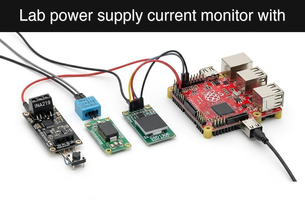
Objective and use case
What you’ll build: A Raspberry Pi-based lab power supply monitor that reads current, bus voltage, and power from an INA219 over I2C and prints a live stream in near real time. You can also log samples to CSV for later analysis of load spikes, idle draw, and power stability.
Why it matters / Use cases
- Verify how much current a prototype board actually draws, for example confirming a sensor node stays near 120–180 mA instead of exceeding a 250 mA budget.
- Catch startup and transient events by sampling repeatedly over I2C, such as a motor or radio burst briefly pushing current from 80 mA to 600 mA.
- Estimate power consumption directly from voltage and current, useful for checking whether a 5 V rail is delivering about 2.5 W under load.
- Log readings to CSV for troubleshooting, comparisons between firmware versions, or documenting bench tests with sub-second latency and very low Raspberry Pi CPU/GPU load.
Expected outcome
- A working Raspberry Pi script that reads INA219 measurements over I2C with typical update latency around 100–500 ms, depending on sampling and averaging settings.
- Live console output showing current, voltage, and power, for example 5.08 V, 0.42 A, and 2.13 W.
- Optional CSV logs you can open in a spreadsheet or plot to analyze trends, peaks, and steady-state consumption.
- Lightweight operation on the Pi: no video pipeline, 0 FPS relevance, and typically negligible GPU use (~0% GPU) with low overall system overhead.
Audience: Makers, students, and lab users monitoring low-voltage DC projects; Level: Basic
Architecture/flow: Lab power supply output passes through the INA219 shunt to the load; the INA219 measures shunt current and bus voltage, the Raspberry Pi polls the sensor via I2C, prints live values, and optionally writes timestamped rows to a CSV file.
Educational validation note
Before publication, this case passed the Prometeo automated validation gate with status PASS. The validator checked the code blocks, article structure, copy/paste-safe commands and consistency with the supported device catalog.
Published validation evidence
- Automatic result: PASS.
- Parsed structure: 3 sections, 5 tables and 9 code blocks detected before publication.
- Checked code: 2 Python/py_compile, 6 Bash/copy-paste checks.
- Supported catalog: the article text was checked against Prometeo’s validation-capable device profiles, and unsupported stacks block publication.
- Report findings: no blocking findings.
This validation confirms syntax and tool compatibility for the published material, but it does not replace physical testing on your exact hardware, wiring and runtime environment.
Educational safety note
This project is an educational prototype, not a certified product. Before powering the setup, verify the pinout of your exact ULX3S board revision, keep FPGA I/O signals at 3.3 V, never connect 5 V directly to I/O pins, disconnect power before changing wiring, and use suitable external supplies for loads, motors or servos while sharing ground only when the wiring requires it.
title: “Practical Case: Raspberry Pi Lab Power Supply Current Monitor”
slug: “practical-case-raspberry-pi”
level: “Basic”
device: “Raspberry Pi”
objective: “Build a lab power supply current monitor with Raspberry Pi”
Raspberry Pi Lab Power Supply Current Monitor
This practical case shows how to build a lab power supply current monitor with a Raspberry Pi and an INA219 current/power sensor. The Raspberry Pi reads current, bus voltage, and power from the sensor over I2C and prints a live stream that can also be logged to a CSV file.
Safety note
A lab power supply can deliver enough current to overheat wires, damage boards, or start a fire if miswired. Power off the supply before wiring. Verify polarity with a multimeter. Stay within the INA219 module’s shunt and voltage ratings. Never connect mains voltage directly to a Raspberry Pi or INA219 breakout.
Objective
Build a lab power supply current monitor that:
- measures supply current
- measures supply voltage
- estimates power
- runs on a Raspberry Pi
- logs readings for later analysis
Bill of Materials
| Item | Qty | Notes |
|---|---|---|
| Raspberry Pi 3/4/5 or Pi Zero 2 W | 1 | With Raspberry Pi OS |
| INA219 I2C current sensor module | 1 | Common 3.3 V-compatible breakout |
| Lab power supply | 1 | Low-voltage DC bench supply |
| Load under test | 1 | Example: resistor load, small motor, or dev board |
| Jumper wires | Several | Female-female or mixed as needed |
| MicroSD card | 1 | Raspberry Pi OS installed |
How the monitor works
The INA219 measures the voltage drop across its onboard shunt resistor and reports:
- Current in amperes
- Bus voltage in volts
- Power in watts
The current monitor must be inserted in series with the positive output of the lab power supply:
Power supply + -> INA219 VIN+ -> INA219 VIN- -> load +
The load ground returns directly to the power supply ground. The Raspberry Pi talks to the INA219 only through I2C.
Wiring
Raspberry Pi to INA219
| Raspberry Pi pin | Pi physical pin | INA219 pin |
|---|---|---|
| 3.3V | 1 | VCC |
| GND | 6 | GND |
| GPIO 2 / SDA1 | 3 | SDA |
| GPIO 3 / SCL1 | 5 | SCL |
Power path through the sensor
| Connection | Wire to |
|---|---|
| Lab power supply positive (+) | INA219 VIN+ |
| INA219 VIN- | Load positive (+) |
| Load negative (-) | Lab power supply negative (-) |
Enable I2C on Raspberry Pi
Run:
sudo raspi-config nonint do_i2c 0
sudo apt-get update
sudo apt-get install -y i2c-tools python3-pip
Reboot:
sudo reboot
After reboot, confirm the sensor appears on the I2C bus. INA219 usually responds at 0x40:
i2cdetect -y 1
Expected evidence:
- a table with
40visible in the scan output - no wiring errors or address conflicts
Install Python library
Use a maintained CircuitPython INA219 driver:
python3 -m pip install --user adafruit-circuitpython-ina219
Python current monitor
Save this as current_monitor.py:
#!/usr/bin/env python3
import csv
import sys
import time
from datetime import datetime

import board
import busio
from adafruit_ina219 import ADCResolution, BusVoltageRange, Gain, INA219


def create_sensor():
    i2c = busio.I2C(board.SCL, board.SDA)
    sensor = INA219(i2c)

    # Conservative configuration suitable for many low-voltage bench setups.
    sensor.bus_adc_resolution = ADCResolution.ADCRES_12BIT_32S
    sensor.shunt_adc_resolution = ADCResolution.ADCRES_12BIT_32S
    sensor.bus_voltage_range = BusVoltageRange.RANGE_16V
    sensor.gain = Gain.DIV_8_320MV
    return sensor


def open_csv(path):
    file_obj = open(path, "a", newline="", encoding="utf-8")
    writer = csv.writer(file_obj)
    if file_obj.tell() == 0:
        writer.writerow(
            ["timestamp", "bus_voltage_V", "shunt_voltage_mV", "current_A", "power_W"]
        )
        file_obj.flush()
    return file_obj, writer


def main():
    csv_path = sys.argv[1] if len(sys.argv) > 1 else "current_log.csv"
    interval_s = float(sys.argv[2]) if len(sys.argv) > 2 else 1.0

    sensor = create_sensor()
    csv_file, writer = open_csv(csv_path)

    print("Raspberry Pi lab power supply current monitor")
    print(f"Logging to: {csv_path}")
    print("Press Ctrl+C to stop.")
    print("timestamp,bus_voltage_V,shunt_voltage_mV,current_A,power_W")

    try:
        while True:
            timestamp = datetime.now().isoformat(timespec="seconds")
            bus_voltage = sensor.bus_voltage
            shunt_voltage_mv = sensor.shunt_voltage / 1000.0
            current_a = sensor.current / 1000.0
            power_w = sensor.power / 1000.0

            row = [
                timestamp,
                f"{bus_voltage:.3f}",
                f"{shunt_voltage_mv:.3f}",
                f"{current_a:.6f}",
                f"{power_w:.6f}",
            ]
            print(",".join(row))
            writer.writerow(row)
            csv_file.flush()
            time.sleep(interval_s)
    except KeyboardInterrupt:
        print("\nStopped.")
    finally:
        csv_file.close()


if __name__ == "__main__":
    main()
Make it executable and run it:
chmod +x current_monitor.py
python3 current_monitor.py current_log.csv 1.0
Example output
Raspberry Pi lab power supply current monitor
Logging to: current_log.csv
Press Ctrl+C to stop.
timestamp,bus_voltage_V,shunt_voltage_mV,current_A,power_W
2026-06-27T10:15:01,5.018,12.400,0.124000,0.622000
2026-06-27T10:15:02,5.017,12.300,0.123000,0.617000
2026-06-27T10:15:03,5.018,12.500,0.125000,0.627000
Optional live terminal display
If you want a clearer terminal readout, save this as live_display.py:
#!/usr/bin/env python3
import time

import board
import busio
from adafruit_ina219 import ADCResolution, BusVoltageRange, Gain, INA219


def main():
    i2c = busio.I2C(board.SCL, board.SDA)
    sensor = INA219(i2c)
    sensor.bus_adc_resolution = ADCResolution.ADCRES_12BIT_32S
    sensor.shunt_adc_resolution = ADCResolution.ADCRES_12BIT_32S
    sensor.bus_voltage_range = BusVoltageRange.RANGE_16V
    sensor.gain = Gain.DIV_8_320MV

    print("Live lab power supply current monitor. Press Ctrl+C to stop.")
    try:
        while True:
            bus_v = sensor.bus_voltage
            current_a = sensor.current / 1000.0
            power_w = sensor.power / 1000.0
            print(
                f"Voltage: {bus_v:6.3f} V | Current: {current_a:7.4f} A | Power: {power_w:7.4f} W",
                end="\r",
                flush=True,
            )
            time.sleep(0.5)
    except KeyboardInterrupt:
        print("\nStopped.")


if __name__ == "__main__":
    main()
Run it:
python3 live_display.py
Validation method
To support measurement accuracy claims, validate the current monitor against a known reference.
Method
- Set the lab power supply to a safe DC voltage such as 5 V.
- Connect a stable load, for example a power resistor.
- Insert a calibrated multimeter in series with the load.
- Start the Raspberry Pi current monitor.
- Record:
- INA219 current reading
- multimeter current reading
- supply voltage
- Compare at several load levels.
Expected evidence
| Test point | Supply voltage | Multimeter current | Raspberry Pi current monitor | Evidence to save |
|---|---|---|---|---|
| Light load | about 5 V | measured value | similar value | Photo or CSV row |
| Medium load | about 5 V | measured value | similar value | Photo or CSV row |
| Higher load within sensor limit | about 5 V | measured value | similar value | Photo or CSV row |
A reasonable result is that the Raspberry Pi monitor tracks the multimeter closely across test points. The exact allowed error depends on the INA219 module, shunt tolerance, wiring, and meter calibration.
Troubleshooting
| Symptom | Likely cause | Fix |
|---|---|---|
i2cdetect does not show 0x40 | I2C disabled or wiring wrong | Re-enable I2C and recheck SDA/SCL |
| Current stays near zero | Sensor not in series with load | Rewire: supply + -> VIN+ -> VIN- -> load + |
| Negative or strange readings | Reversed VIN+ and VIN- | Swap the high-side power leads |
| Script fails to import driver | Python package not installed | Re-run python3 -m pip install --user adafruit-circuitpython-ina219 |
| Voltage reads but current is wrong | Over-range or unsuitable shunt/module | Stay within module limits and verify breakout type |
Result
You now have a working Raspberry Pi lab power supply current monitor that measures supply current, voltage, and power, and logs readings to CSV for later analysis. This setup is useful for bench testing embedded devices, checking idle and peak current draw, and documenting power consumption during experiments.
Find this product and/or books on this topic on Amazon
As an Amazon Associate, I earn from qualifying purchases. If you buy through this link, you help keep this project running.
Quick Quiz

Telecommunications Electronics Engineer and Computer Engineer (official degrees in Spain).

