
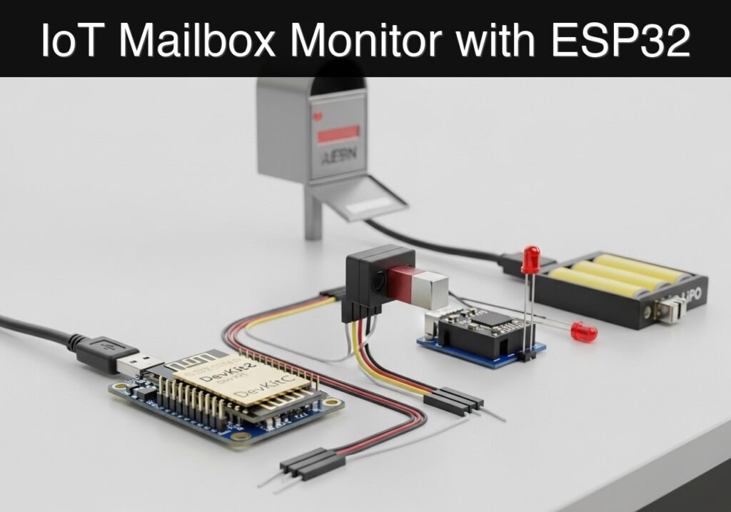
Objective and use case
What you’ll build: A battery-powered, highly efficient IoT mailbox monitor that remains in a micro-power deep sleep state, wakes up instantly when the mailbox door opens, transmits a Wi-Fi alert via an HTTP GET request, and immediately returns to sleep.
Why it matters / Use cases
- Eliminates wasted trips: Users no longer need to physically check an empty mailbox in harsh weather or across long driveways.
- Maximizes battery lifecycle: By utilizing the ESP32’s deep sleep capabilities (drawing ~10µA), the device minimizes active duty cycles, demonstrating crucial power-budgeting skills.
- Event-driven architecture: Teaches the transition from continuous polling to hardware-interrupt-driven wakeups, a foundational concept in commercial sensor networks.
- Security and access logging: The same architecture can be repurposed for monitoring restricted cabinets, safes, or perimeter gates without requiring hardwired power.
Expected outcome
- The ESP32 enters a deep sleep state drawing minimal current (sub-15µA).
- Opening the door triggers a hardware wake-up via the RTC (Real-Time Clock) GPIO within 500 milliseconds.
- The device successfully connects to Wi-Fi, transmits the HTTP payload, and powers down in under 3 seconds to preserve battery life.
Audience: IoT Developers, Embedded Engineers; Level: Intermediate
Architecture/flow: Reed Switch (Hardware Interrupt) → ESP32 RTC Wake-up (<500ms latency) → Wi-Fi Connect → HTTP GET Request → Deep Sleep
Educational validation note
Before publication, this case passed the Prometeo automated validation gate with status PASS. For this ESP32 DevKitC profile, the project was checked as a PlatformIO project: the validator extracted platformio.ini and src/main.cpp, created a temporary project and ran pio run against platform = espressif32, board = esp32dev and framework = arduino. It also checked article structure, copy/paste-safe ASCII command options, and unsupported stacks such as direct ESP-IDF or non-scoped ESP32 boards.
Published validation evidence
- Automatic result: PASS.
- Parsed structure: 3 sections, 3 tables and 2 code blocks detected before publication.
- Checked code: 1 PlatformIO config + 1 ESP32 source/pio run.
- Supported catalog: the article text was checked against Prometeo’s validation-capable device profiles, and unsupported stacks block publication.
- Report findings: no blocking findings.
This validation confirms syntax and tool compatibility for the published code, but it does not replace physical testing on your exact ESP32 DevKitC board, wiring, power supply and local WiFi environment.
Educational safety note
Warning regarding prototype limits: This project is intended strictly as an educational prototype.
* Battery Safety: This project involves Lithium Polymer (LiPo) batteries. Mishandling, overcharging, or short-circuiting LiPo batteries can result in fire or explosion. Always use a dedicated charge controller (like the TP4056 with built-in protection circuitry) and never connect a LiPo cell directly to the ESP32 without proper voltage regulation. Do not leave experimental battery circuits unattended while charging. Ensure your battery module includes over-discharge protection to prevent cell damage during long deployments.
Conceptual block diagram
High-level view: what enters the system, what each block processes, and what comes out.
Functional architecture
Conceptual flow: local configuration, BLE advertising and phone-side reading.

Validation path
Conceptual summary of the tools used to check the published ESP32 project.

Prerequisites
Before starting this tutorial, ensure you have the following ready:
* A computer running Windows, macOS, or Linux.
* Visual Studio Code (VSCode) installed.
* The PlatformIO IDE extension installed within VSCode.
* Basic familiarity with C++ syntax and electronic circuits (pull-up/pull-down networks).
* A 2.4 GHz Wi-Fi network (ESP32 does not support 5 GHz Wi-Fi).
* A local HTTP server or a webhook endpoint to receive the alert.
Materials
For this project, use the following exact hardware configuration:
* ESP32 DevKitC: The core microcontroller board featuring the ESP-WROOM-32 module.
* Reed switch: A magnetic contact switch (normally open). When the magnet is near, the switch closes. When the magnet is removed (door opens), the switch opens.
* LiPo battery module: A 3.7V Lithium Polymer battery paired with a 5V boost/charge module (e.g., a TP4056-based power bank module) to safely supply 5V to the ESP32 DevKitC’s 5V (or VIN) pin.
* Passive Components:
* One 10kΩ resistor (used as a pull-down resistor for the reed switch).
* Accessories: Breadboard, jumper wires, and a micro-USB data cable.
Setup/Connection
Hardware Setup Notes
The ESP32 DevKitC requires specific drivers to communicate over USB. Depending on your exact board revision, it will use either a CP210x or CH34x USB-to-UART bridge. If your board is not recognized by your operating system or PlatformIO, download and install the official Silicon Labs CP210x or WCH CH340 drivers.
Circuit Logic
The core of this project is the hardware interrupt. The ESP32’s main processor is turned off during deep sleep. Only the Ultra-Low Power (ULP) coprocessor and the RTC memory/peripherals remain active. We will use the ext0 wake-up source, which allows an RTC GPIO to wake the main processor when a specific logic level is detected.
We will use GPIO 33 (an RTC-capable pin) for the reed switch.
* Mailbox Closed: The magnet is near the reed switch. The switch is closed, connecting GPIO 33 to 3.3V. The ESP32 sees a HIGH signal.
* Mailbox Open: The door opens, the magnet moves away, and the switch opens. The 10kΩ pull-down resistor forces GPIO 33 to LOW.
* Wake-up condition: We will configure the ESP32 to wake up when GPIO 33 goes LOW.
Wiring Table
| Component | Pin/Terminal | ESP32 DevKitC Pin | Notes |
|---|---|---|---|
| LiPo Battery Module | 5V Output / VOUT | 5V (or VIN) | Provides power when USB is disconnected. |
| LiPo Battery Module | GND / Ground | GND | Common ground. |
| Reed Switch | Terminal 1 | 3V3 | Provides 3.3V when switch is closed. |
| Reed Switch | Terminal 2 | GPIO 33 | Signal pin for RTC wake-up. |
| 10kΩ Resistor | Leg 1 | GPIO 33 | Pull-down configuration. |
| 10kΩ Resistor | Leg 2 | GND | Pull-down configuration. |
Note: Disconnect the LiPo battery module’s 5V line from the ESP32 when plugging the ESP32 into your computer via USB to avoid power contention.
Application Firmware
The following code handles the deep sleep transition, Wi-Fi connection, HTTP request, and hardware wake-up logic.
platformio.ini
Create a new PlatformIO project for the ESP32 DevKitC and replace the contents of platformio.ini with the following configuration:
[env:esp32dev]
platform = espressif32
board = esp32dev
framework = arduino
monitor_speed = 115200
upload_speed = 921600
src/main.cpp
Replace the contents of src/main.cpp with the following code. Update the network and webhook variables to match your environment before deploying.
Public preview of the validated file. The complete source is shown to members and in PDF/Print.
#include <Arduino.h>
#include <WiFi.h>
#include <HTTPClient.h>

// ==========================================
// Configuration
// ==========================================
const char* WIFI_SSID     = "IoT_Network";
const char* WIFI_PASSWORD = "SecurePassword123";
const char* WEBHOOK_URL   = "http://192.168.1.100/mailbox-alert";

// Pin Definitions
const gpio_num_t REED_SWITCH_PIN = GPIO_NUM_33; // Must be an RTC GPIO for ext0 wakeup

// Timeouts
const int WIFI_TIMEOUT_MS = 10000; // 10 seconds max to connect

// ==========================================
// Helper Functions
// ==========================================

void printWakeupReason() {
    esp_sleep_wakeup_cause_t wakeup_reason = esp_sleep_get_wakeup_cause();
    switch(wakeup_reason) {
        case ESP_SLEEP_WAKEUP_EXT0:
            Serial.println("Wakeup caused by external signal using RTC_IO (Door Opened!)");
            break;
        case ESP_SLEEP_WAKEUP_TIMER:
            Serial.println("Wakeup caused by timer");
            break;
        default:
            Serial.printf("Wakeup was not caused by deep sleep: %d\n", wakeup_reason);
            break;
    }
}

void sendAlert() {
    Serial.print("Connecting to Wi-Fi: ");
    Serial.println(WIFI_SSID);

    WiFi.begin(WIFI_SSID, WIFI_PASSWORD);

    unsigned long startAttemptTime = millis();

    // Wait for connection with a timeout to prevent draining battery
    while (WiFi.status() != WL_CONNECTED && millis() - startAttemptTime < WIFI_TIMEOUT_MS) {
        Serial.print(".");
        delay(500);
    }

    Serial.println();

    if (WiFi.status() != WL_CONNECTED) {
        Serial.println("Failed to connect to Wi-Fi. Going back to sleep.");
        return; // Abort and let the main loop put the device to sleep
    }
// ...#include <Arduino.h>
#include <WiFi.h>
#include <HTTPClient.h>
// ==========================================
// Configuration
// ==========================================
const char* WIFI_SSID = "IoT_Network";
const char* WIFI_PASSWORD = "SecurePassword123";
const char* WEBHOOK_URL = "http://192.168.1.100/mailbox-alert";
// Pin Definitions
const gpio_num_t REED_SWITCH_PIN = GPIO_NUM_33; // Must be an RTC GPIO for ext0 wakeup
// Timeouts
const int WIFI_TIMEOUT_MS = 10000; // 10 seconds max to connect
// ==========================================
// Helper Functions
// ==========================================
void printWakeupReason() {
esp_sleep_wakeup_cause_t wakeup_reason = esp_sleep_get_wakeup_cause();
switch(wakeup_reason) {
case ESP_SLEEP_WAKEUP_EXT0:
Serial.println("Wakeup caused by external signal using RTC_IO (Door Opened!)");
break;
case ESP_SLEEP_WAKEUP_TIMER:
Serial.println("Wakeup caused by timer");
break;
default:
Serial.printf("Wakeup was not caused by deep sleep: %d\n", wakeup_reason);
break;
}
}
void sendAlert() {
Serial.print("Connecting to Wi-Fi: ");
Serial.println(WIFI_SSID);
WiFi.begin(WIFI_SSID, WIFI_PASSWORD);
unsigned long startAttemptTime = millis();
// Wait for connection with a timeout to prevent draining battery
while (WiFi.status() != WL_CONNECTED && millis() - startAttemptTime < WIFI_TIMEOUT_MS) {
Serial.print(".");
delay(500);
}
Serial.println();
if (WiFi.status() != WL_CONNECTED) {
Serial.println("Failed to connect to Wi-Fi. Going back to sleep.");
return; // Abort and let the main loop put the device to sleep
}
    Serial.println("Wi-Fi connected!");
    Serial.print("IP address: ");
    Serial.println(WiFi.localIP());

    // Send HTTP GET request
    if (WiFi.status() == WL_CONNECTED) {
        HTTPClient http;
        Serial.print("Sending alert to: ");
        Serial.println(WEBHOOK_URL);

        http.begin(WEBHOOK_URL);
        int httpResponseCode = http.GET();

        if (httpResponseCode > 0) {
            Serial.print("HTTP Response code: ");
            Serial.println(httpResponseCode);
        } else {
            Serial.print("Error code: ");
            Serial.println(httpResponseCode);
        }
        http.end();
    }

    // Disconnect Wi-Fi to save power before sleeping
    WiFi.disconnect(true);
    WiFi.mode(WIFI_OFF);
}
// ==========================================
// Main Setup and Loop
// ==========================================
void setup() {
Serial.begin(115200);
delay(1000); // Allow serial monitor to catch up
Serial.println("\n--- Mailbox Monitor Booting ---");
// Determine why the ESP32 woke up
esp_sleep_wakeup_cause_t wakeup_reason = esp_sleep_get_wakeup_cause();
printWakeupReason();
// If woke up because the door opened (EXT0)
if (wakeup_reason == ESP_SLEEP_WAKEUP_EXT0) {
sendAlert();
} else {
// Normal boot (e.g., first power on or reset)
Serial.println("Initial boot. System is armed and ready.");
}
// Configure Deep Sleep Wakeup
// Door open = magnet away = switch open = pull-down resistor pulls to LOW (0).
// Wake up when GPIO 33 goes LOW (0).
esp_sleep_enable_ext0_wakeup(REED_SWITCH_PIN, 0);
Serial.println("Entering deep sleep now. Waiting for door to open...");
Serial.flush();
// Enter Deep Sleep
esp_deep_sleep_start();
}
void loop() {
// The loop is intentionally empty.
// The ESP32 goes to sleep in setup() and resets entirely upon waking.
}
Build/Flash/Run commands
To deploy the code to your ESP32 DevKitC using PlatformIO, use the built-in terminal in VSCode.
Command Reference
| Action | Command | Purpose |
|---|---|---|
| Compile Code | pio run | Compiles the C++ code and libraries without uploading. |
| Upload Firmware | pio run --target upload | Flashes the compiled binary to the ESP32 via USB. |
| Serial Monitor | pio device monitor | Opens the terminal to view Serial.print outputs. |
Workflow
- Connect the ESP32 DevKitC to your computer using a data-capable micro-USB cable.
- Open the VSCode terminal in your project directory.
- Compile and upload the firmware by running:
pio run --target upload - Immediately open the serial monitor to observe the boot sequence:
pio device monitor
Step-by-step Validation
Follow these grouped checkpoints to ensure your prototype functions correctly.
- Initial Boot & Arming
- Action: Press the
EN(Reset) button on the ESP32. - Expected observation: The Serial Monitor prints “Initial boot. System is armed and ready.” The monitor then prints “Entering deep sleep now.”
- Pass condition: The device successfully enters deep sleep without immediately waking back up.
- Action: Press the
- Simulating Mailbox Closed
- Action: Place the magnet directly next to the reed switch.
- Expected observation: Nothing happens. The ESP32 remains in deep sleep.
- Pass condition: The system ignores the closed state (GPIO 33 is HIGH).
- Triggering the Wake-up (Mailbox Opened)
- Action: Quickly pull the magnet away from the reed switch.
- Expected observation: The Serial Monitor prints “Wakeup caused by external signal using RTC_IO (Door Opened!)”.
- Pass condition: The hardware interrupt successfully wakes the ESP32 from deep sleep.
- Network Connection and Transmission
- Action: Wait 2 to 5 seconds while watching the Serial Monitor.
- Expected observation: Monitor prints “Wi-Fi connected!”, followed by the IP address, and then “HTTP Response code: 200”.
- Pass condition: The webhook endpoint registers the incoming GET request.
- Return to Sleep
- Action: Observe the final serial outputs.
- Expected observation: Monitor prints “Entering deep sleep now. Waiting for door to open…”
- Pass condition: The ESP32 drops the Wi-Fi connection and powers down its main processor, ready for the next event.
Troubleshooting
If the system does not behave as expected, consult the table below.
| Symptom | Likely cause | Fix |
|---|---|---|
| Code fails to upload (Timeout) | ESP32 is not entering bootloader mode. | Hold the BOOT button on the DevKitC while running the upload command, release when connecting begins. |
| Constant wake-up loops | Reed switch logic is floating. | Verify the 10kΩ pull-down resistor is securely connected between GPIO 33 and GND. Ensure the magnet is close enough to close the switch initially. |
| Wi-Fi connection fails / Times out | Incorrect credentials or 5GHz network. | Verify WIFI_SSID and WIFI_PASSWORD. Ensure your router is broadcasting a 2.4GHz network. |
| Brownout detector triggered | Insufficient power during Wi-Fi transmission. | The USB port or LiPo module cannot supply the ~300mA spike required for Wi-Fi. Try a better USB cable or ensure the LiPo battery is fully charged. |
| No output on Serial Monitor | Baud rate mismatch. | Ensure monitor_speed = 115200 is set in platformio.ini and matches Serial.begin(115200) in the code. |
Improvements
Once the basic prototype is validated, consider these enhancements for a production-ready device:
- Power Optimization:
- Static IP: Assign a static IP address to the ESP32 instead of using DHCP. This can reduce Wi-Fi connection time from ~3 seconds to under 500ms, drastically saving battery life.
- Hardware LDO replacement: Standard ESP32 DevKitC boards use an AMS1117 voltage regulator with a high quiescent current (~1.5mA). For true micro-power operation, transition to a custom board or a low-dropout regulator (LDO) like the HT7333.
- Connectivity & Reliability:
- MQTT Implementation: Replace the HTTP GET request with an MQTT publish via the
PubSubClientlibrary. MQTT has lower overhead and is better suited for IoT ecosystems. - Battery Voltage Monitoring: Wire the LiPo battery output to an ESP32 ADC pin (via a voltage divider) to transmit battery health alongside the open-door alert.
- MQTT Implementation: Replace the HTTP GET request with an MQTT publish via the
Find this product and/or books on this topic on Amazon
As an Amazon Associate, I earn from qualifying purchases. If you buy through this link, you help keep this project running.
Quick Quiz

Telecommunications Electronics Engineer and Computer Engineer (official degrees in Spain).

